SIK Experiment Guide for the Arduino 101/Genuino 101 Board (Chinese)
This Tutorial is Retired!
This tutorial covers concepts or technologies that are no longer current. It's still here for you to read and enjoy, but may not be as useful as our newest tutorials.
 D___Run___
 实验 6:读取 SPDT 开关
简介
在前面的实验中,您使用了按钮作为数字输入。在本实验中,您将探索另一个数字输入,即 SPDT(单刀 - 双掷)开关。您将使用该开关选择两个 LED 中的哪个会闪烁。
所需部件
您需要以下部件:
- 1x 实验电路板
- 1x Arduino 101 或 Genuino 101 开发板
- 2x LED(1 个红色,1 个黄色)
- 2x 100Ω 电阻
- 8x 跳线
- 1x SPDT 开关
没有 SIK?
如果您要执行本实验,但又没有 SIK,那么我们建议您使用这些部件:


您还需要一个 Arduino 101 或 Genuino 101 开发板。

Arduino 101
DEV-13787
Genuino 101
DEV-13984推荐阅读
继续进行本教程之前,我们建议您熟悉一下这些教程中的概念:
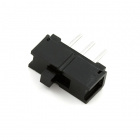
单刀 - 双掷 (SPDT) 开关简介

单刀 - 双掷 (SPDT) 开关在中央有一个公共针脚,此外是其他两个针脚,它们根据开关的位置,会连接到或未连接到公共(中央)针脚。要采用与按钮相似的方式读取开关,需要将公共针脚连接到 101 开发板上的数字通用输入/输出 (GPIO) 针脚,并将其他针脚连接到 3.3V 和接地。哪个针脚连接到哪个位置并不重要。移动开关时,公共针脚会是 HIGH(连接到 3.3V)或 LOW(接地)。
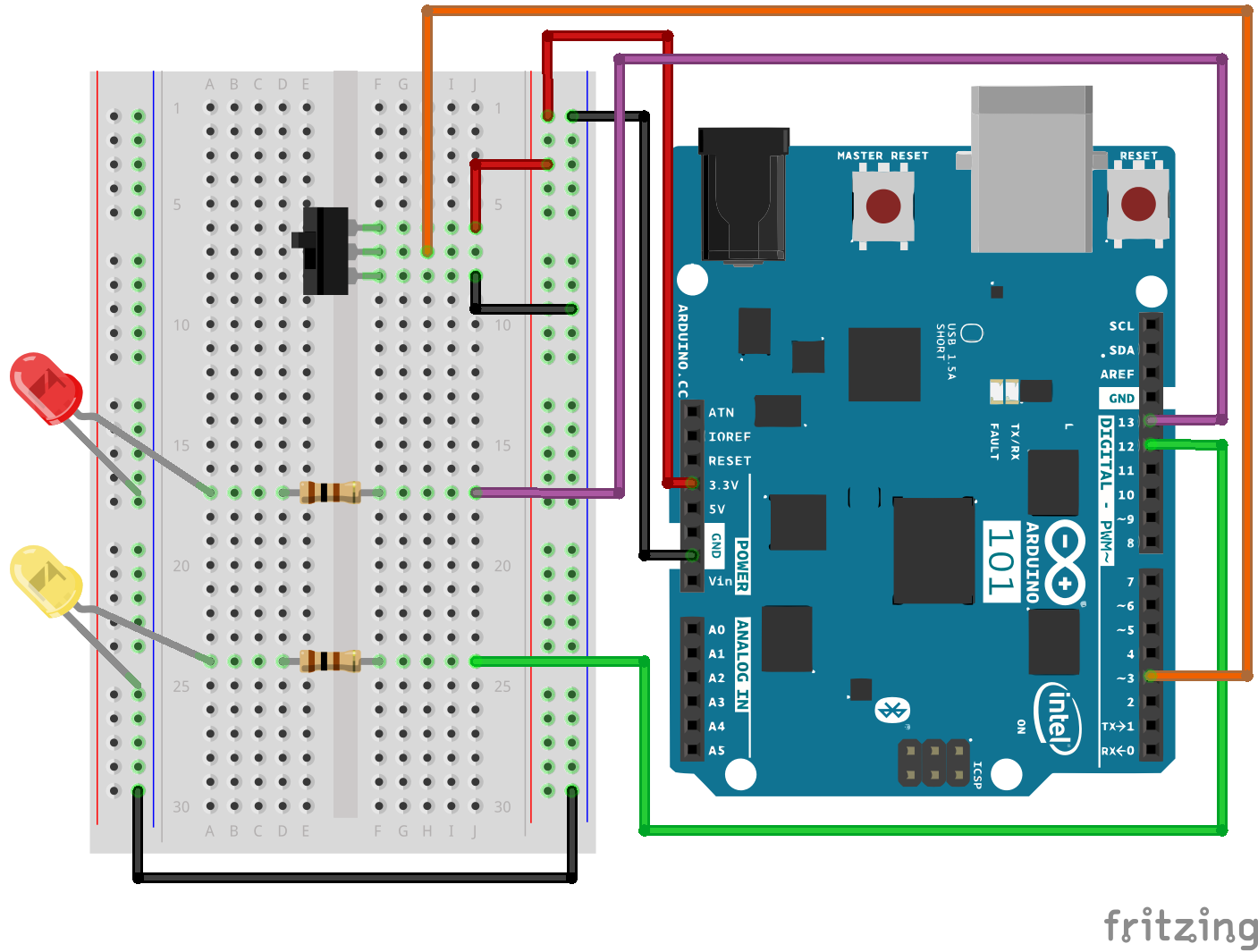
硬件接线
是否准备好开始对每个部件进行接线?请查看下面的接线图和接线表以了解如何连接每个部件。
| 极化组件 | 请特别注意组件用于指示如何在实验电路板上放置它的标记。极化组件只能按一个方向连接到电路。 |
实验的接线图
打开草图
在计算机上打开 Arduino IDE 软件。采用 Arduino 语言进行编码可控制电路。通过访问您先前下载并置于“示例”文件夹中的“101 SIK 指南代码”,来打开用于电路 6 的代码。
要打开该代码,请转到:文件 > 示例 > 101 SIK 指南代码 > Circuit_06
还可以将以下代码复制并粘贴到 Arduino IDE 中。点击“上传”,然后查看发生的情况!
language:cpp
/*
SparkFun Inventor's Kit
Example sketch 06

SPDT Switch

Use a Single Pole - Double Throw Switch (SPDT) to select an LED to blink

This sketch was written by SparkFun Electronics,
with lots of help from the Arduino community.
This code is completely free for any use.
Visit http://learn.sparkfun.com/products/2 for SIK information.
Visit http://www.arduino.cc to learn more about Arduino.
*/

// Create constants for the pins we will be using
const int switchPin = 3;
const int led1Pin = 12;
const int led2Pin =  13;

void setup()
{
  // Set up the switch pins to be an input:
  pinMode(switchPin, INPUT);

  // Set up the LED pins to be an output:
  pinMode(led1Pin,OUTPUT);
  pinMode(led2Pin,OUTPUT);
}

void loop()
{
  // variables to hold the switch state
  int switchVal;

  // Since a switch has only two states, either HIGH (3.3V)
  // or LOW (GND) there is no way for you to have a floating point situation so there       //is no need for a pulldown resistor.

  //store the switch value to the switchVal variable
  switchVal = digitalRead(switchPin);

 //if switchVal is HIGH blink led1Pin
 if(switchVal == HIGH)
 {
   digitalWrite(led1Pin,HIGH);
   delay(500);
   digitalWrite(led1Pin,LOW);
   delay(500);
 }
 //else blink led2Pin
 else
 {
   digitalWrite(led2Pin,HIGH);
   delay(500);
   digitalWrite(led2Pin,LOW);
   delay(500);
 }
}
要注意的代码
pinMode(switchPin, INPUT);
数字针脚可以用作输入以及输出。执行任一操作之前,需要向 Arduino 101 告知您的目标方向。
switchVal = digitalRead(switchPin);
要读取数字输入,可使用 digitalRead() 函数。它会在针脚上存在 3.3V 时返回 HIGH,在针脚上存在 0V 时返回 LOW。
if (switchVal == LOW)
因为我们已将按钮连接到 GND,所以它会在按下时读为 LOW。我们在这里使用“等值”运算符(“==”)来了解是否按下了按钮。
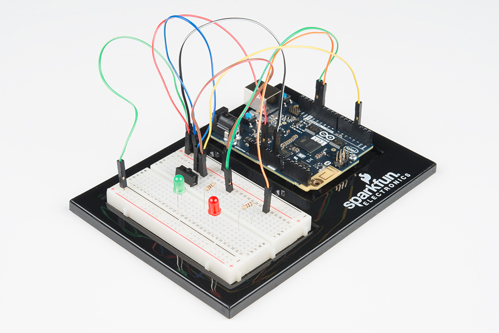
应看到的情况
根据开关的状态,不同的 LED 将闪烁。如果移动开关以将信号针脚连接到 3.3V (HIGH),则 LED 1 将闪烁。如果反转开关并使信号针脚接地,则 LED 2 将开始闪烁,LED 1 将熄灭。
故障诊断
指示灯未亮起
开关的导线彼此紧挨着。确保信号位于中央,而电压和接地位于外侧针脚上。如果将接地与电压连接在一起,则开发板会短路并关闭。
确保电源 LED 已亮起。如果它熄灭,请从针脚 3 拔出信号导线,查看是否更改了任何内容。如果 101 开发板短路,则它会关闭自己以保护电路。您还可能必须重新启动计算机以便可以重新访问串行端口。
感到乏味
别担心;这些电路全都极其精简,以便您能轻松尝试使用各个组件,但是一旦您将它们组合在一起,便可获得无穷乐趣。