SIK Experiment Guide for the Arduino 101/Genuino 101 Board (Chinese)
This Tutorial is Retired!
This tutorial covers concepts or technologies that are no longer current. It's still here for you to read and enjoy, but may not be as useful as our newest tutorials.
 D___Run___
 实验 5:读取按下按钮操作
简介
到目前为止,我们将大部分精力集中在输出上。现在我们将转到另一方面,来尝试使用输入。在实验 2 中,我们使用了一个模拟输入来读取电位计。在本实验中,我们将使用数字输入读取最常见且简单的输入之一 – 按钮。我们将使用它在 RGB 上循环显示不同颜色。
所需部件
您需要以下部件:
- 1x 实验电路板
- 1x Arduino 101 或 Genuino 101 开发板
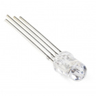
- 1x RGB LED
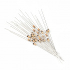
- 1x 100Ω 电阻
- 8x 跳线
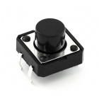
- 1x 按钮
- 1x 10K 电阻
没有 SIK?
如果您要执行本实验,但又没有 SIK,那么我们建议您使用这些部件:


您还需要一个 Arduino 101 或 Genuino 101 开发板。

Arduino 101
DEV-13787
Genuino 101
DEV-13984推荐阅读
继续进行本教程之前,我们建议您熟悉一下这些教程中的概念:
按钮简介
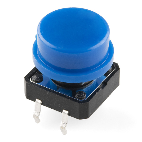
瞬息按钮仅当按下时才会关闭或完成电路。按钮具有四个针脚,它们分为两组,每组两个针脚。按下按钮并听到清脆的“咔哒”声时,按钮会桥接两组针脚,使电流流过电路。
如何知道哪些针脚已进行配对?此工具包中包含的按钮仅在一个方向上跨实验电路板沟槽进行安装。将按钮牢固地按入实验电路板(跨沟槽)之后,针脚按水平方向配对。朝向实验电路板顶部的针脚连接在一起,朝向实验电路板底部的针脚连接在一起。
注:并非所有按钮都采用此针脚格式。请参阅特定按钮的数据表以确定哪些针脚已进行配对。
硬件接线
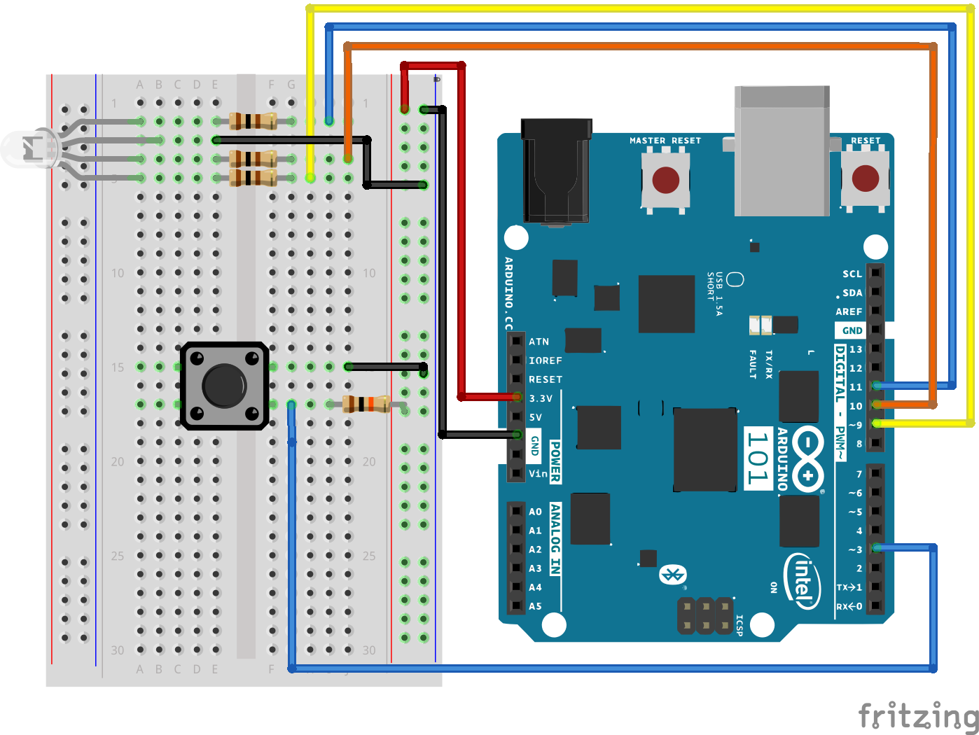
是否准备好开始对每个部件进行接线?请查看下面的接线图和接线表以了解如何连接每个部件。
| 极化组件 | 请特别注意组件用于指示如何在实验电路板上放置它的标记。极化组件只能按一个方向连接到电路。 |
实验的接线图
数字输入
我们以前曾将模拟针脚用于输入;现在我们还会将数字针脚用于输入。因为数字针脚只能识别 HIGH 和 LOW 信号,所以它们十分适用于与也只有“开”和“关”状态的按钮和开关相连接。
我们将按钮的一端接地,将另一端连接到数字针脚。当我们按下按钮时,针脚会接地,因此会由 Arduino 开发板读为“LOW”。
不过别着急 -- 未按下按钮时会发生什么情况?在此状态下,针脚会与任何对象断开连接,我们称之为“浮动”。那么针脚会读为什么?HIGH 还是 LOW?这难以判断,因为没有与 3.3V 或接地之间的实体连接。针脚可能读为任一状态。
为了解决此问题,我们将在信号针脚与 3.3V 之间连接一个小型(10K 或 10,000 欧姆)电阻。此“上拉”电阻会确保当您未按下按钮时,针脚仍具有与 3.3 伏之间的弱连接,因此读为 HIGH。
高级:当您习惯于使用上拉电阻并且知道何时需要使用它们时,您可以在 Arduino 中的 ATmega 处理器上激活内部上拉电阻。请参阅 http://arduino.cc/en/Tutorial/DigitalPins 以获取信息。
打开草图
在计算机上打开 Arduino IDE 软件。采用 Arduino 语言进行编码可控制电路。通过访问您先前下载并置于“示例”文件夹中的“101 SIK 指南代码”,来打开用于电路 5 的代码。
要打开该代码,请转到:文件 > 示例 > 101 SIK 指南代码 > Circuit_05
还可以将以下代码复制并粘贴到 Arduino IDE 中。点击“上传”,然后查看发生的情况!
language:cpp
/*
SparkFun Inventor's Kit
Example sketch 05

PUSH BUTTONS

  Use pushbuttons for digital input

This sketch was written by SparkFun Electronics,
with lots of help from the Arduino community.
This code is completely free for any use.
Visit http://learn.sparkfun.com/products/2 for SIK information.
Visit http://www.arduino.cc to learn about the Arduino.

*/

// First we'll set up constants for the pin numbers.
// This will make it easier to follow the code below.

 // pushbutton pin
 const int buttonPin = 3;

 //RGB LED pins
 const int redPin = 11;
 const int greenPin = 10;
 const int bluePin = 9;

//create a variable to store a counter and set it to 0
int counter = 0;
void setup()
{
  // Set up the pushbutton pins to be an input:
  pinMode(buttonPin, INPUT);

  // Set up the RGB pins to be an outputs:
  pinMode(redPin, OUTPUT);
  pinMode(greenPin,OUTPUT);
  pinMode(bluePin,OUTPUT);
}

void loop()
{
 // local variable to hold the pushbutton states
  int buttonState;

  //read the digital state of buttonPin with digitalRead() function and store the           //value in buttonState variable
  buttonState = digitalRead(buttonPin);

  //if the button is pressed increment counter and wait a tiny bit to give us some          //time to release the button
  if (buttonState == LOW) // light the LED
  {
    counter++;
    delay(150);
  }

  //use the if satement to check the value of counter. If counter is equal to 0 all         //pins are off
  if(counter == 0)
  {
   digitalWrite(redPin,LOW);
   digitalWrite(greenPin,LOW);
   digitalWrite(bluePin,LOW);
  }

  //else if counter is equal to 1, redPin is HIGH
  else if(counter == 1)
  {
   digitalWrite(redPin,HIGH);
   digitalWrite(greenPin,LOW);
   digitalWrite(bluePin,LOW);
  }

  //else if counter is equal to 2 greenPin is HIGH
  else if(counter ==2)
  {
   digitalWrite(redPin,LOW);
   digitalWrite(greenPin,HIGH);
   digitalWrite(bluePin,LOW);
  }

  //else if counter is equal to 3 bluePin is HIGH
  else if(counter ==3)
  {
   digitalWrite(redPin,LOW);
   digitalWrite(greenPin,LOW);
   digitalWrite(bluePin,HIGH);
  }

  //else reset the counter to 0 (which turns all pins off)
  else
  {
   counter =0;
  }
}
要注意的代码
pinMode(buttonPin, INPUT);
数字针脚可以用作输入以及输出。执行任一操作之前,需要向 Arduino 告知您的目标方向。
buttonState = digitalRead(buttonPin);
要读取数字输入,可使用 digitalRead() 函数。它会在针脚上存在 3.3V 时返回 HIGH,在针脚上存在 0V 时返回 LOW。
if (button1State == LOW)
因为我们已将按钮连接到 GND,所以它会在按下时读为 LOW。我们在这里使用“等值”运算符(“==”)来了解是否按下了按钮。
应看到的情况
您应在按下任一按钮时看到 LED 亮起,在同时按下两个按钮时看到 LED 熄灭。(请查看代码以查明原因!)如果它未运行,请确保正确装配了电路以及验证了代码并将它上传到开发板,或查看“故障诊断”部分。

故障诊断
指示灯未亮起
按钮是方形的,因此容易将其放错。将它旋转 90 度,然后看看它是否开始运行。
感到乏味
别担心;这些电路全都极其精简,以便您能轻松尝试使用各个组件,但是一旦您将它们组合在一起,便可获得无穷乐趣。