SIK Experiment Guide for Arduino - V3.3
This Tutorial is Retired!
View the updated tutorial: SparkFun Inventor's Kit Experiment Guide - v4.0
 HelloTechie,
  Toni_K
Experiment 14: Using a Shift Register
Introduction
Now we are going to step into the world of ICs (integrated circuits). In this circuit, you’ll learn all about using a shift register (also called a serial-to-parallel converter). The shift register will give your RedBoard or Arduino Uno R3 an additional eight outputs, using only three pins on your board. For this circuit, you’ll practice by using the shift register to control eight LEDs.
Parts Needed
You will need the following parts:
- 1x RedBoard + USB mini-B Cable or Arduino Uno R3 + USB A-to-B Cable
- 1x Breadboard
- 19x Jumper Wires
- 8x 330Ω Resistor
8x LEDs 1x Shift Register 8-Bit - SN74HC595)
Suggested Reading
Before continuing on with this experiment, we recommend you be familiar with the concepts in the following tutorial:
Hardware Hookup
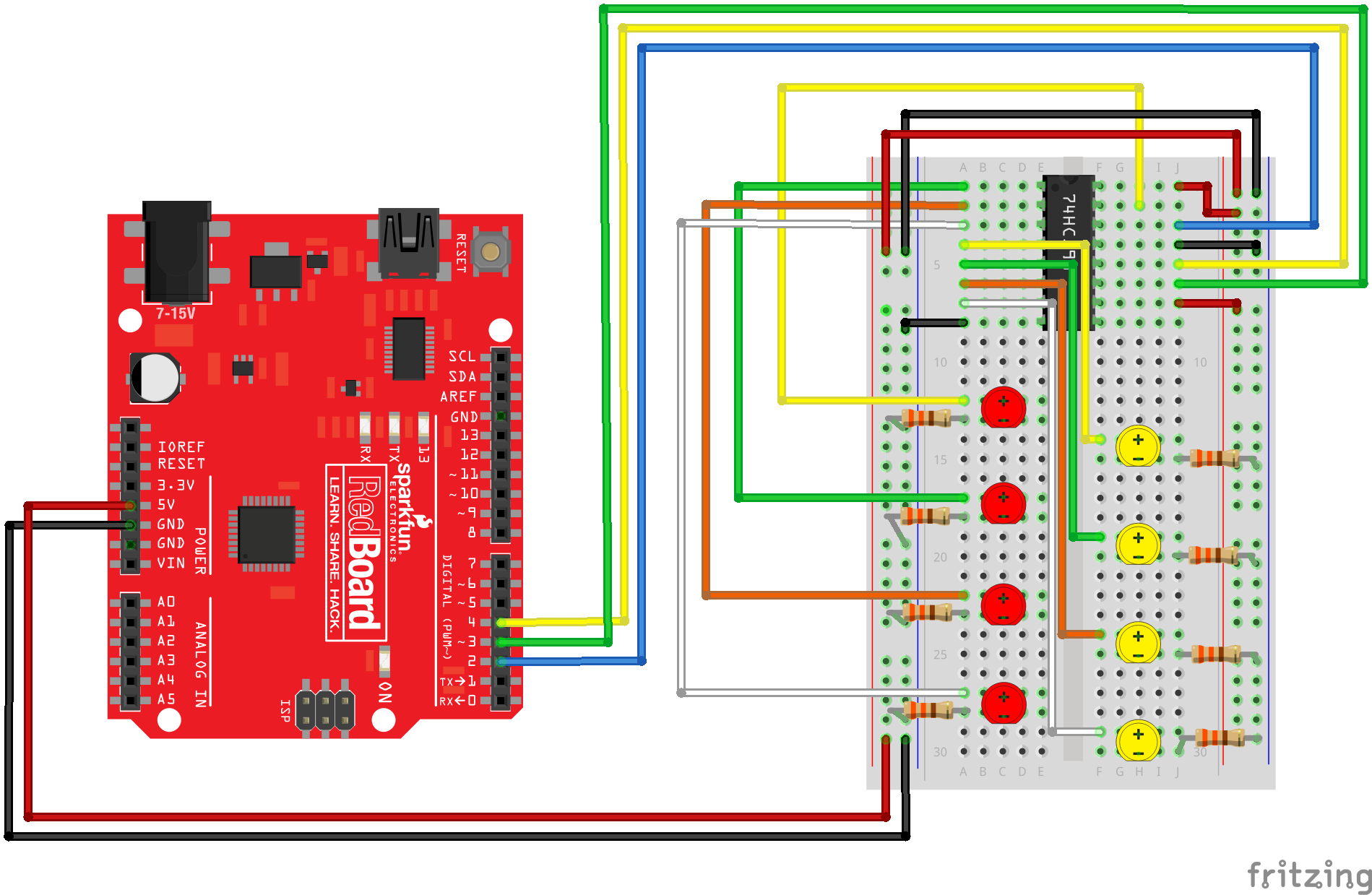
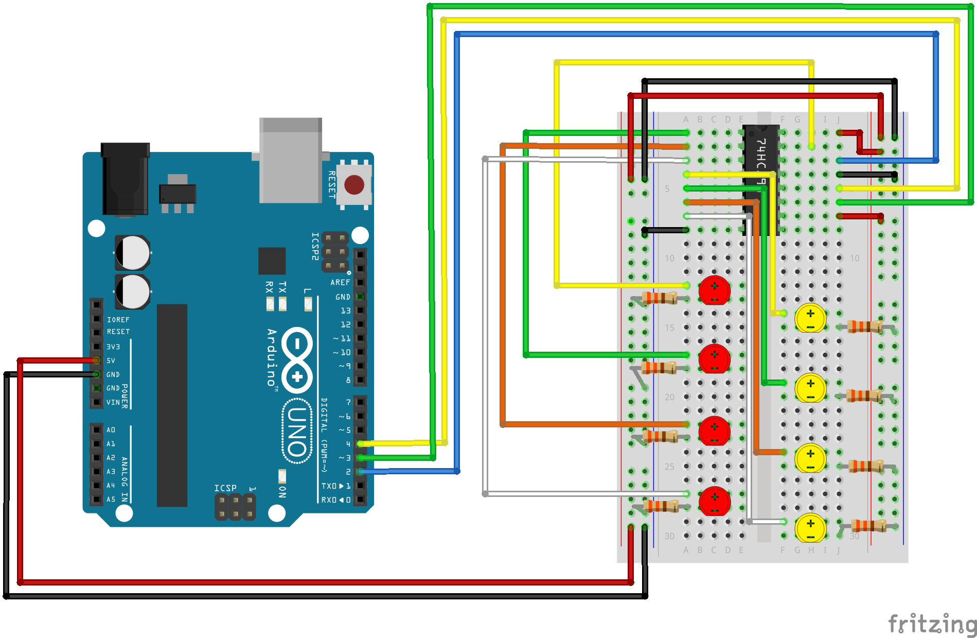
Ready to start hooking everything up? Check out the Fritzing diagram below, to see how everything is connected.
| Polarized Components | Pay special attention to the component’s markings indicating how to place it on the breadboard. Polarized components can only be connected to a circuit in one direction. |
For the shift register, align notch on top, in-between “e1” and “f1” on the breadboard. The notch indicates where pin 1 is.
Fritzing Diagram for RedBoard
Fritzing Diagram for Arduino
Open the Sketch
Open Up the Arduino IDE software on your computer. Coding in the Arduino language will control your circuit. Open the code for Circuit 14 by accessing the “SIK Guide Code” you downloaded and placed into your “Examples” folder earlier.
To open the code go to: File > Examples > SIK Guide Code > SIK_circuit14_shiftRegister
You can also copy and paste the following code into the Arduino IDE. Hit upload, and see what happens!
language:cpp
/*
SparkFun Inventor's Kit
Example sketch 14
SHIFT REGISTER
  Use a shift register to turn three pins into eight (or more!)
  outputs
  An integrated circuit ("IC"), or "chip", is a self-contained
  circuit built into a small plastic package. (If you look closely
  at your Arduino board you'll see a number of ICs.) There are
  thousands of different types of ICs available that you can use
  to perform many useful functions.
  The 74HC595 shift register in your kit is an IC that has eight
  digital outputs. To use these outputs, we'll use a new interface
  called SPI (Serial Peripheral Interface). It's like the TX and
  RX you're used to, but has an additional "clock" line that
  controls the speed of the data transfer. Many parts use SPI
  for communications, so the Arduino offers simple commands called
  shiftIn() and shiftOut() to access these parts.
  This IC lets you use three digital pins on your Arduino to
  control eight digital outputs on the chip. And if you need
  even more outputs, you can daisy-chain multiple shift registers
  together, allowing an almost unlimited number of outputs from
  the same three Arduino pins! See the shift register datasheet
  for details:

  http://www.sparkfun.com/datasheets/IC/SN74HC595.pdf

This sketch was written by SparkFun Electronics,
with lots of help from the Arduino community.
This code is completely free for any use.
Visit http://learn.sparkfun.com/products/2 for SIK information.
Visit http://www.arduino.cc to learn about the Arduino.
Version 2.0 6/2012 MDG
*/


// Pin definitions:
// The 74HC595 uses a type of serial connection called SPI
// (Serial Peripheral Interface) that requires three pins:

int datapin = 2;
int clockpin = 3;
int latchpin = 4;

// We'll also declare a global variable for the data we're
// sending to the shift register:

byte data = 0;


void setup()
{
  // Set the three SPI pins to be outputs:

  pinMode(datapin, OUTPUT);
  pinMode(clockpin, OUTPUT);
  pinMode(latchpin, OUTPUT);
}


void loop()
{

  // To try the different functions below, uncomment the one
  // you want to run, and comment out the remaining ones to
  // disable them from running.

  oneAfterAnother();      // All on, all off

  //oneOnAtATime();       // Scroll down the line

  //pingPong();           // Like above, but back and forth

  //randomLED();          // Blink random LEDs

  //marquee();

  //binaryCount();        // Bit patterns from 0 to 255
}


void shiftWrite(int desiredPin, boolean desiredState){

// This function lets you make the shift register outputs
// HIGH or LOW in exactly the same way that you use digitalWrite().

  bitWrite(data,desiredPin,desiredState); //Change desired bit to 0 or 1 in "data"

  // Now we'll actually send that data to the shift register.
  // The shiftOut() function does all the hard work of
  // manipulating the data and clock pins to move the data
  // into the shift register:

  shiftOut(datapin, clockpin, MSBFIRST, data); //Send "data" to the shift register

  //Toggle the latchPin to make "data" appear at the outputs
  digitalWrite(latchpin, HIGH);
  digitalWrite(latchpin, LOW);
}


void oneAfterAnother()
{
// This function will turn on all the LEDs, one-by-one,
// and then turn them off all off, one-by-one.

  int index;
  int delayTime = 100; // Time (milliseconds) to pause between LEDs
                       // Make this smaller for faster switching

  // Turn all the LEDs on
  for(index = 0; index <= 7; index++)
  {
    shiftWrite(index, HIGH);
    delay(delayTime);
  }

  // Turn all the LEDs off
  for(index = 7; index >= 0; index--)
  {
    shiftWrite(index, LOW);
    delay(delayTime);
  }
}


void oneOnAtATime()
{
// This function will turn the LEDs on and off, one-by-one.
  int index;
  int delayTime = 100; // Time (milliseconds) to pause between LEDs
                       // Make this smaller for faster switching

  // step through the LEDs, from 0 to 7

  for(index = 0; index <= 7; index++)
  {
    shiftWrite(index, HIGH);    // turn LED on
    delay(delayTime);       // pause to slow down the sequence
    shiftWrite(index, LOW); // turn LED off
  }
}

void pingPong()
{
// This function turns on the LEDs, one at a time, in both directions.
  int index;
  int delayTime = 100; // time (milliseconds) to pause between LEDs
                       // make this smaller for faster switching

  // step through the LEDs, from 0 to 7

  for(index = 0; index <= 7; index++)
  {
    shiftWrite(index, HIGH);    // turn LED on
    delay(delayTime);       // pause to slow down the sequence
    shiftWrite(index, LOW); // turn LED off
  }

  // step through the LEDs, from 7 to 0

  for(index = 7; index >= 0; index--)
  {
    shiftWrite(index, HIGH);    // turn LED on
    delay(delayTime);       // pause to slow down the sequence
    shiftWrite(index, LOW); // turn LED off
  }
}

void randomLED()
{
// This function will randomly turn on and off LEDs.
  int index;
  int delayTime = 100; // time (milliseconds) to pause between LEDs
                       // make this smaller for faster switching

  index = random(8);    // pick a random number between 0 and 7

  shiftWrite(index, HIGH);  // turn LED on
  delay(delayTime);     // pause to slow down the sequence
  shiftWrite(index, LOW);   // turn LED off
}

void marquee()
{
// This function will mimic "chase lights" like those around signs.
  int index;
  int delayTime = 200; // Time (milliseconds) to pause between LEDs
                       // Make this smaller for faster switching

  // Step through the first four LEDs
  // (We'll light up one in the lower 4 and one in the upper 4)

  for(index = 0; index <= 3; index++)
  {
    shiftWrite(index, HIGH);    // Turn a LED on
    shiftWrite(index+4, HIGH);  // Skip four, and turn that LED on
    delay(delayTime);       // Pause to slow down the sequence
    shiftWrite(index, LOW); // Turn both LEDs off
    shiftWrite(index+4, LOW);
  }
}


void binaryCount()
{
// This function creates a visual representation of the on/off pattern
// of bits in a byte.

  int delayTime = 1000; // time (milliseconds) to pause between LEDs
                        // make this smaller for faster switching

  // Send the data byte to the shift register:

  shiftOut(datapin, clockpin, MSBFIRST, data);

  // Toggle the latch pin to make the data appear at the outputs:

  digitalWrite(latchpin, HIGH);
  digitalWrite(latchpin, LOW);

  // Add one to data, and repeat!
  // (Because a byte type can only store numbers from 0 to 255,
  // if we add more than that, it will "roll around" back to 0
  // and start over).

  data++;

  // Delay so you can see what's going on:

  delay(delayTime);
}
Code To Note
shiftOut(datapin, clockpin, MSBFIRST, data);
You'll communicate with the shift register (and a lot of other parts) using an interface called SPI, or Serial Peripheral Interface. This interface uses a data line and a separate clock line that work together to move data into or out of the Arduino at high speed. The MSBFIRST parameter specifies the order in which to send the individual bits, in this case we're sending the Most Significant Bit first.
bitWrite(data, desiredPin, desiredState);
Bits are the smallest possible piece of memory in a computer; each one can store either a "1" or a "0". Larger numbers are stored as arrays of bits. Sometimes we want to manipulate these bits directly, for example now when we're sending eight bits to the shift register and we want to make them 1 or 0 to turn the LEDs on or off. The Arduino has several commands, such as bitWrite(), that make this easy to do.
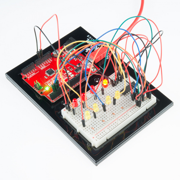
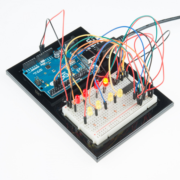
What You Should See
You should see the LEDs light up similarly to experiment 4 (but this time, you're using a shift register). If they aren't, make sure you have assembled the circuit correctly and verified and uploaded the code to your board. See the troubleshooting section.
Real World Application
Similar to experiment 4, a scrolling marquee display delivers a message with multiple LEDs. Essentially the same task the shift register achieves here in experiment 14. You might be asking yourself, "why bother using a shift register if we already have more than 8 outputs?" One reason is that you may have a project where you've already used up most of your output pins for other uses. A shift register allows you to add eight more output pins for the price of only three!
Troubleshooting
The Arduino's power LED goes out
This happened to us a couple of times, it happens when the chip is inserted backward. If you fix it quickly nothing will break.
Not Quite Working
Sorry to sound like a broken record, but it is probably something as simple as a crossed wire.
Frustration
Shoot us an e-mail, this circuit is both simple and complex at the same time. We want to hear about problems you have so we can address them in future editions: techsupport@sparkfun.com