SIK Experiment Guide for Arduino - V3.3
This Tutorial is Retired!
View the updated tutorial: SparkFun Inventor's Kit Experiment Guide - v4.0
 HelloTechie,
  Toni_K
Experiment 10: Reading a Soft Potentiometer
Introduction
In this circuit, we are going to use yet another kind of variable resistor – this time, a soft potentiometer (or soft pot). This is a thin and flexible strip that can detect where pressure is being applied. By pressing down on various parts of the strip, you can vary the resistance from 100 to 10k ohms. You can use this ability to track movement on the soft pot, or simply as a button. In this circuit, we’ll get the soft pot up and running to control an RGB LED.
Parts Needed
You will need the following parts:
- 1x RedBoard + USB mini-B Cable or Arduino Uno R3 + USB A-to-B Cable
- 1x Breadboard
- 9x Jumper Wires
- 1x 10k resistor
- 1x Soft Potentiometer
- 3x 330Ω resistors
1x LED - RGB Common Cathode
Hardware Hookup
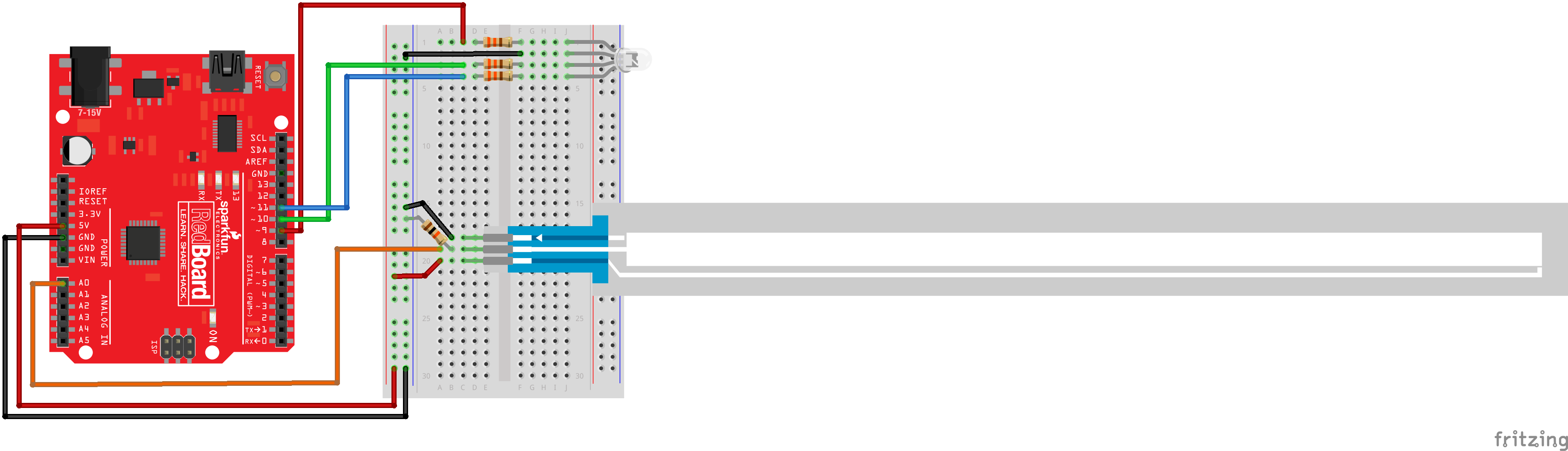
Ready to start hooking everything up? Check out the Fritzing diagram below, to see how everything is connected.
| Polarized Components | Pay special attention to the component’s markings indicating how to place it on the breadboard. Polarized components can only be connected to a circuit in one direction. |
Fritzing Diagram for RedBoard
Fritzing Diagram for Arduino

Open the Sketch
Open Up the Arduino IDE software on your computer. Coding in the Arduino language will control your circuit. Open the code for Circuit 10 by accessing the “SIK Guide Code” you downloaded and placed into your “Examples” folder earlier.
To open the code go to: File > Examples > SIK Guide Code > SIK_circuit10_softPotentiometer
You can also copy and paste the following code into the Arduino IDE. Hit upload, and see what happens!
language:cpp
 /*
SparkFun Inventor's Kit
Example sketch 10
SOFT POTENTIOMETER
  Use the soft potentiometer to change the color
  of the RGB LED
  The soft potentiometer is a neat input device that detects
  pressure along its length. When you press it down with a finger
  (it works best on a flat surface), it will change resistance
  depending on where you're pressing it. You might use it to make
  a piano or light dimmer; here we're going to use it to control
  the color of an RGB LED.

This sketch was written by SparkFun Electronics,
with lots of help from the Arduino community.
This code is completely free for any use.
Visit http://learn.sparkfun.com/products/2 for SIK information.
Visit http://www.arduino.cc to learn about the Arduino.
Version 2.0 6/2012 MDG
*/


// Constants for LED connections
const int RED_LED_PIN = 9;    // Red LED Pin
const int GREEN_LED_PIN = 10; // Green LED Pin
const int BLUE_LED_PIN = 11;  // Blue LED Pin

const int SENSOR_PIN = 0;      // Analog input pin

// Global PWM brightness values for the RGB LED.
// These are global so both loop() and setRGB() can see them.

int redValue, greenValue, blueValue;


void setup()
{
  // No need for any code here
  // analogWrite() sets up the pins as outputs
}


void loop()
{
  int sensorValue;

  sensorValue = analogRead(SENSOR_PIN); // Read the voltage from the softpot (0-1023)

  setRGB(sensorValue);  //Set a RGB LED to a position on the "rainbow" of all colors
                        //based on the sensorValue
}

void setRGB(int RGBposition)
{
  int mapRGB1, mapRGB2, constrained1, constrained2;

  mapRGB1 = map(RGBposition, 0, 341, 255, 0);
  constrained1 = constrain(mapRGB1, 0, 255);

  mapRGB2 = map(RGBposition, 682, 1023, 0, 255);
  constrained2 = constrain(mapRGB2, 0, 255);

  redValue = constrained1 + constrained2; //Create the red peak

  //Create the green peak
  //Note that we are nesting functions (which requires fewer variables)

  greenValue = constrain(map(RGBposition, 0, 341, 0, 255), 0, 255)
             - constrain(map(RGBposition, 341, 682, 0,255), 0, 255);

  //Create the blue peak
  blueValue = constrain(map(RGBposition, 341, 682, 0, 255), 0, 255)
            - constrain(map(RGBposition, 682, 1023, 0, 255), 0, 255);

 // Display the new computed "rainbow" color
  analogWrite(RED_LED_PIN, redValue);
  analogWrite(GREEN_LED_PIN, greenValue);
  analogWrite(BLUE_LED_PIN, blueValue);

  }
Code To Note
language:cpp
redValue = constrain(map(RGBposition, 0, 341, 255, 0), 0, 255)
 + constrain(map(RGBposition, 682, 1023, 0, 255), 0, 255);


greenValue = constrain(map(RGBposition, 0, 341, 0, 255), 0, 255)
 - constrain(map(RGBposition, 341, 682, 0,255), 0, 255);


blueValue = constrain(map(RGBposition, 341, 682, 0, 255), 0, 255)
- constrain(map(RGBposition, 682, 1023, 0, 255), 0, 255);
These big, scary functions take a single Value (RGBposition) and calculate the three RGB values necessary to create a rainbow of color. The functions create three "peaks" for the red, green, and blue values, which overlap to mix and create new colors. See the code for more information! Even if you're not 100% clear how it works, you can copy and paste this (or any) function into your own code and use it yourself.
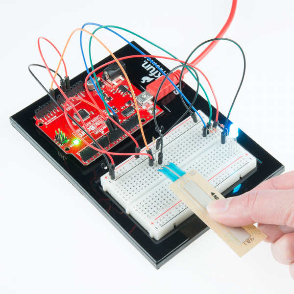
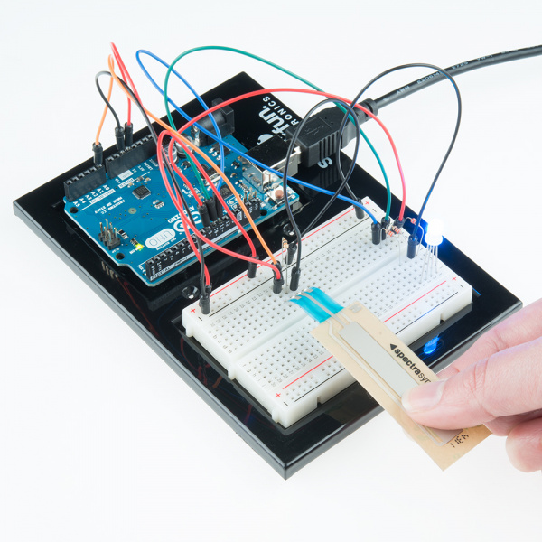
What You Should See
You should see the RGB LED change colors in accordance with how you interact with the soft potentiometer. If it isn't working, make sure you have assembled the circuit correctly and verified and uploaded the code to your board, or see the troubleshooting section.
Real World Application
The knobs found on many objects, like a radio for instance, are using similar concepts to the one you just completed for this circuit.
Troubleshooting
LED Remains Dark or Shows Incorrect Color
With the four pins of the LED so close together, it’s sometimes easy to misplace one. Try double checking each pin is where it should be.
Bizarre Results
The most likely cause of this is if you’re pressing the potentiometer in more than one position. This is normal and can actually be used to create some neat results.