SIK Experiment Guide for Arduino - V3.3
This Tutorial is Retired!
View the updated tutorial: SparkFun Inventor's Kit Experiment Guide - v4.0
 HelloTechie,
  Toni_K
Experiment 2: Reading a Potentiometer
Introduction
In this circuit you’ll work with a potentiometer.
A potentiometer is also known as a variable resistor. When powered with 5V, the middle pin outputs a voltage between 0V and 5V, depending on the position of the knob on the potentiometer. A potentiometer is a perfect demonstration of a variable voltage divider circuit. The voltage is divided proportionate to the resistance between the middle pin and the ground pin. In this circuit, you’ll learn how to use a potentiometer to control the brightness of an LED.
Parts Needed
You will need the following parts:
- 1x RedBoard + USB mini-B Cable or Arduino Uno R3 + USB A-to-B Cable
- 1x Breadboard
1x LED - 1x 330Ω Resistor
- 6x Jumper Wires
- 1x Potentiometer
Suggested Reading
Before continuing on with this experiment, we recommend you be familiar with the concepts in the following tutorial:
Hardware Hookup
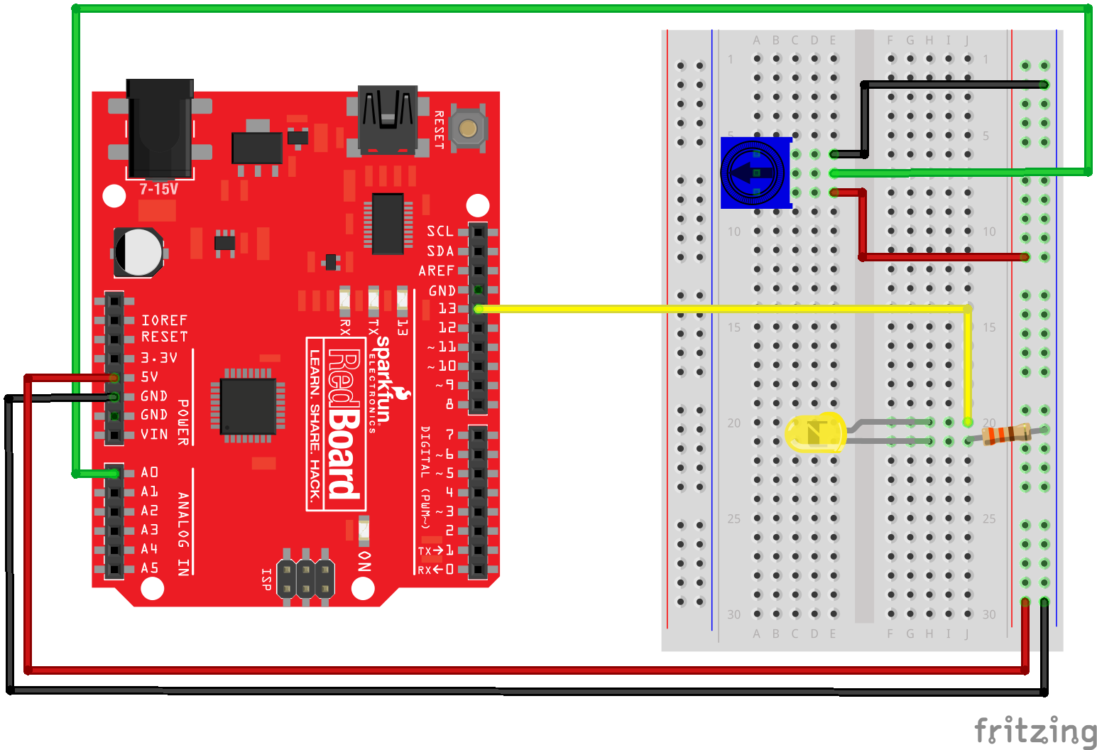
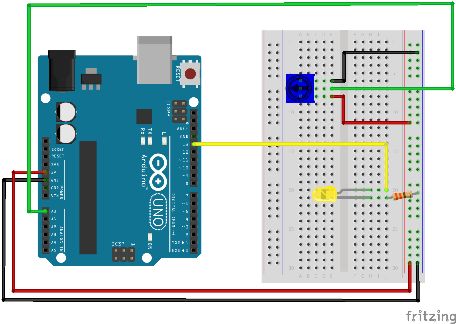
Ready to start hooking everything up? Check out the Fritzing diagram and hookup table below to see how everything is connected.
| Polarized Components | Pay special attention to the component’s markings indicating how to place it on the breadboard. Polarized components can only be connected to a circuit in one direction. |
Fritzing Diagram for RedBoard
Fritzing Diagram for Arduino
Open the Sketch
Open Up the Arduino IDE software on your computer. Coding in the Arduino language will control your circuit. Open the code for Circuit 2 by accessing the “SIK Guide Code” you downloaded and placed into your “Examples” folder earlier.
To open the code go to: File > examples > SIK Guide Code > SIK_circuit02_potentiometer
You can also copy and paste the following code into the Arduino IDE. Hit upload, and see what happens!
language:cpp
   /* SparkFun Inventor's Kit
 Example sketch 02 -- POTENTIOMETER

 Measure the position of a potentiometer and use it to
 control the blink rate of an LED. Turn the knob to make
 it blink faster or slower!

 This sketch was written by SparkFun Electronics,
 with lots of help from the Arduino community.
 This code is completely free for any use.
 Visit http://learn.sparkfun.com/products/2 for SIK information.
 Visit http://www.arduino.cc to learn about the Arduino.

 Version 2.0 6/2012 MDG
 */

int sensorPin = A0;    // The potentiometer is connected to analog pin 0
int ledPin = 13;      // The LED is connected to digital pin 13
int sensorValue;    //We declare another integer variable to store the value of the potentiometer

void setup() // this function runs once when the sketch starts up
{
  pinMode(ledPin, OUTPUT);
}

void loop() // this function runs repeatedly after setup() finishes
{
  sensorValue = analogRead(sensorPin);

  digitalWrite(ledPin, HIGH);     // Turn the LED on
  delay(sensorValue);             // Pause for sensorValue in milliseconds
  digitalWrite(ledPin, LOW);      // Turn the LED off
  delay(sensorValue);             // Pause for sensorValue in milliseconds
}
Code To Note
int sensorValue;
A “variable” is a placeholder for values that may change in your code. You must introduce, or "declare" variables before you use them; here we're declaring a variable called sensorValue, of type "int" (integer). Don't forget that variable names are case-sensitive!
sensorValue = analogRead(sensorPin);
We use the analogRead() function to read the value on an analog pin. analogRead() takes one parameter, the analog pin you want to use ("sensorPin"), and returns a number ("sensorValue") between 0 (0 volts) and 1023 (5 volts).
delay(sensorValue);
Microcontrollers are very fast, capable of running thousands of lines of code each second. To slow it down so that we can see what it's doing, we'll often insert delays into the code. delay() counts in milliseconds; there are 1000 ms in one second.
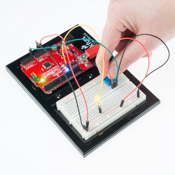
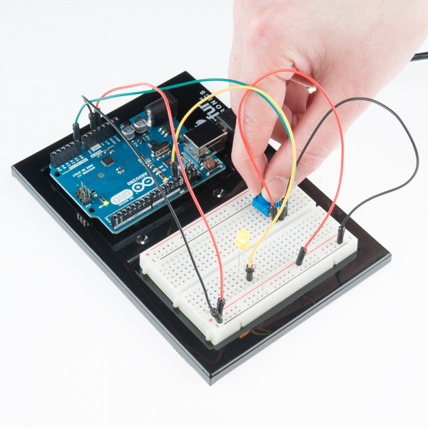
What You Should See
You should see the LED blink faster or slower in accordance with your potentiometer. If it isn't working, make sure you have assembled the circuit correctly and verified and uploaded the code to your board, or see the troubleshooting section.
Real World Application
Most traditional volume knobs employ a potentiometer.
Troubleshooting
Sporadically Working
This is most likely due to a slightly dodgy connection with the potentiometer's pins. This can usually be conquered by holding the potentiometer down.
Not Working
Make sure you haven’t accidentally connected the wiper, the resistive element in the potentiometer, to digital pin 0 rather than analog pin 0. (the row of pins beneath the power pins).
LED Not Lighting Up?
LEDs will only work in one direction. Double check your connections.