SIK Experiment Guide for Arduino - V3.3
This Tutorial is Retired!
View the updated tutorial: SparkFun Inventor's Kit Experiment Guide - v4.0
 HelloTechie,
  Toni_K
Experiment 5: Push Buttons
Introduction
Up until now, we’ve focused mostly on outputs. Now we’re going to go to the other end of spectrum and play around with inputs. In experiment 2, we used an analog input to read the potentiometer. In this circuit, we’ll be reading in one of the most common and simple inputs – a push button – by using a digital input. The way a push button works with your RedBoard or Arduino Uno R3 is that when the button is pushed, the voltage goes LOW. Your RedBoard or Arduino Uno R3 reads this and reacts accordingly.
In this circuit, you will also use a pull-up resistor, which keeps the voltage HIGH when you're not pressing the button.
Parts Needed
You will need the following parts:
- 1x RedBoard + USB mini-B Cable or Arduino Uno R3 + USB A-to-B Cable
- 1x Breadboard
1x LED - 1x 330Ω Resistor
- 7x Jumper Wires
2x Push Buttons - 2x 10k Resistors
Suggested Reading
Before continuing on with this tutorial, we recommend you be somewhat familiar with the concepts in these tutorials:
Hardware Hookup
Ready to start hooking everything up? Check out the Fritzing diagram and hookup table below, to see how everything is connected.
| Polarized Components | Pay special attention to the component’s markings indicating how to place it on the breadboard. Polarized components can only be connected to a circuit in one direction. |
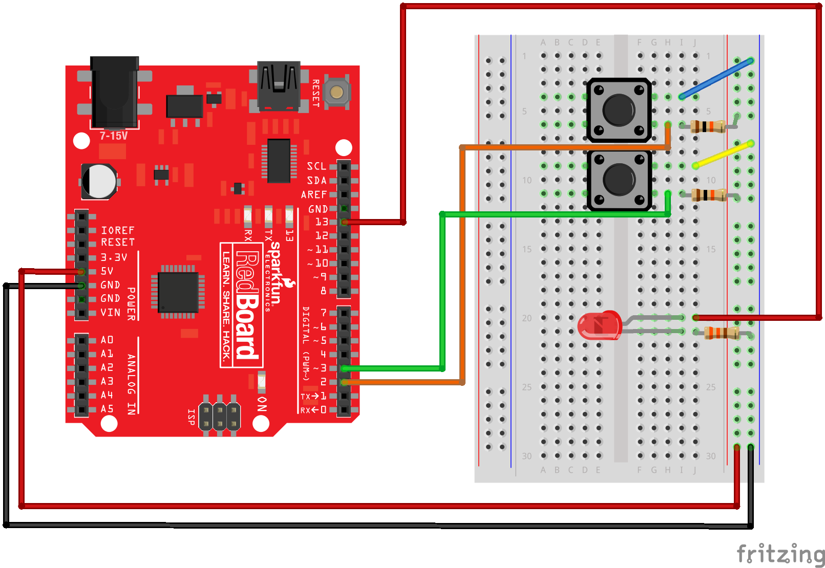
Fritzing Diagram for RedBoard
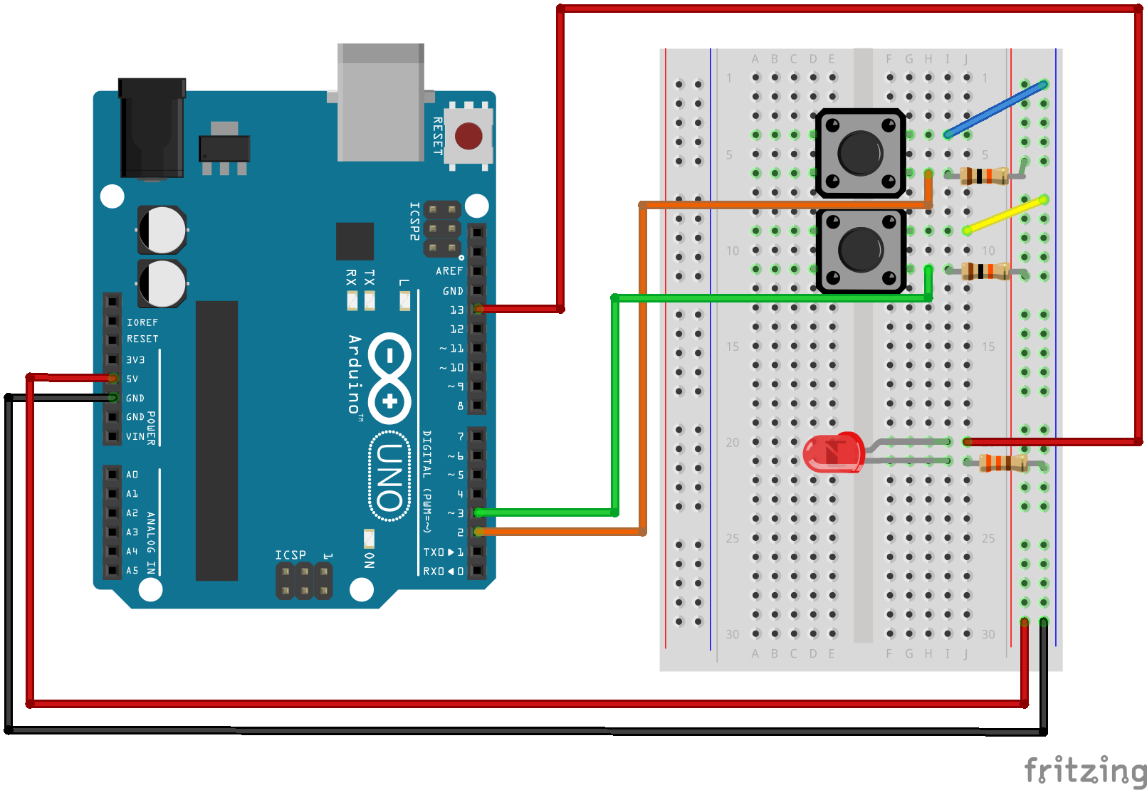
Fritzing Diagram for Arduino
Open the Sketch
Open Up the Arduino IDE software on your computer. Coding in the Arduino language will control your circuit. Open the code for Circuit 5 by accessing the “SIK Guide Code” you downloaded and placed into your “Examples” folder earlier.
To open the code go to: File > examples > SIK Guide Code > SIK_circuit05_pushButton
You can also copy and paste the following code into the Arduino IDE. Hit upload, and see what happens!
language:cpp
/******************************************************************
 * SparkFun Inventor's Kit
 * Example sketch 05 -- PUSH BUTTONS
 *
 *   Use pushbuttons for digital input
 *
 *   Connect one side of the pushbutton to GND, and the other
 *   side to a digital pin. When we press down on the pushbutton,
 *   the pin will be connected to GND, and therefore will be read
 *   as "LOW" by the Arduino.
 *
 * This sketch was written by SparkFun Electronics,
 * with lots of help from the Arduino community.
 * This code is completely free for any use.
 * Visit http://learn.sparkfun.com/products/2 for SIK information.
 * Visit http://www.arduino.cc to learn about the Arduino.
 *
 * Version 2.0 6/2012 MDG
 * Version 2.1 9/2014 BCH
/*****************************************************************/

const int button1Pin = 2;  // pushbutton 1 pin
const int button2Pin = 3;  // pushbutton 2 pin
const int ledPin =  13;    // LED pin

int button1State, button2State;  // variables to hold the pushbutton states


void setup()
{
  // Set up the pushbutton pins to be an input:
  pinMode(button1Pin, INPUT);
  pinMode(button2Pin, INPUT);

  // Set up the LED pin to be an output:
  pinMode(ledPin, OUTPUT);
}

void loop()
{
  button1State = digitalRead(button1Pin);
  button2State = digitalRead(button2Pin);

  // if button1 or button 2 are pressed (but not both)
  if (((button1State == LOW) && (button2State == HIGH)) || ((button1State == HIGH) && (button2State == LOW)))
  {
    digitalWrite(ledPin, HIGH);  // turn the LED on
  }
  else
  {
    digitalWrite(ledPin, LOW);  // turn the LED off
  }
}
Code To Note
pinMode(button2Pin, INPUT);
The digital pins can be used as inputs as well as outputs. Before you do either, you need to tell the Arduino which direction you're going.
button1State = digitalRead(button1Pin);
To read a digital input, you use the digitalRead() function. It will return HIGH if there's 5V present at the pin, or LOW if there's 0V present at the pin.
if (button1State == LOW)
Because we've connected the button to GND, it will read LOW when it's being pressed. Here we're using the "equivalence" operator ("==") to see if the button is being pressed.
What You Should See
You should see the LED turn on if you press either button, and off if you press both buttons. (See the code to find out why!) If it isn't working, make sure you have assembled the circuit correctly and verified and uploaded the code to your board or see the troubleshooting section.

Real World Application
The buttons we used here are similar to the buttons in most video game controllers.
Troubleshooting
Light Not Turning On
The pushbutton is square, and because of this it is easy to put it in the wrong way. Give it a 90 degree twist and see if it starts working.
Underwhelmed
No worries, these circuits are all super stripped down to make playing with the components easy, but once you throw them together the sky is the limit.