AzureWave Thing Plus (AW-CU488) Hookup Guide
 QCPete,
  bboyho
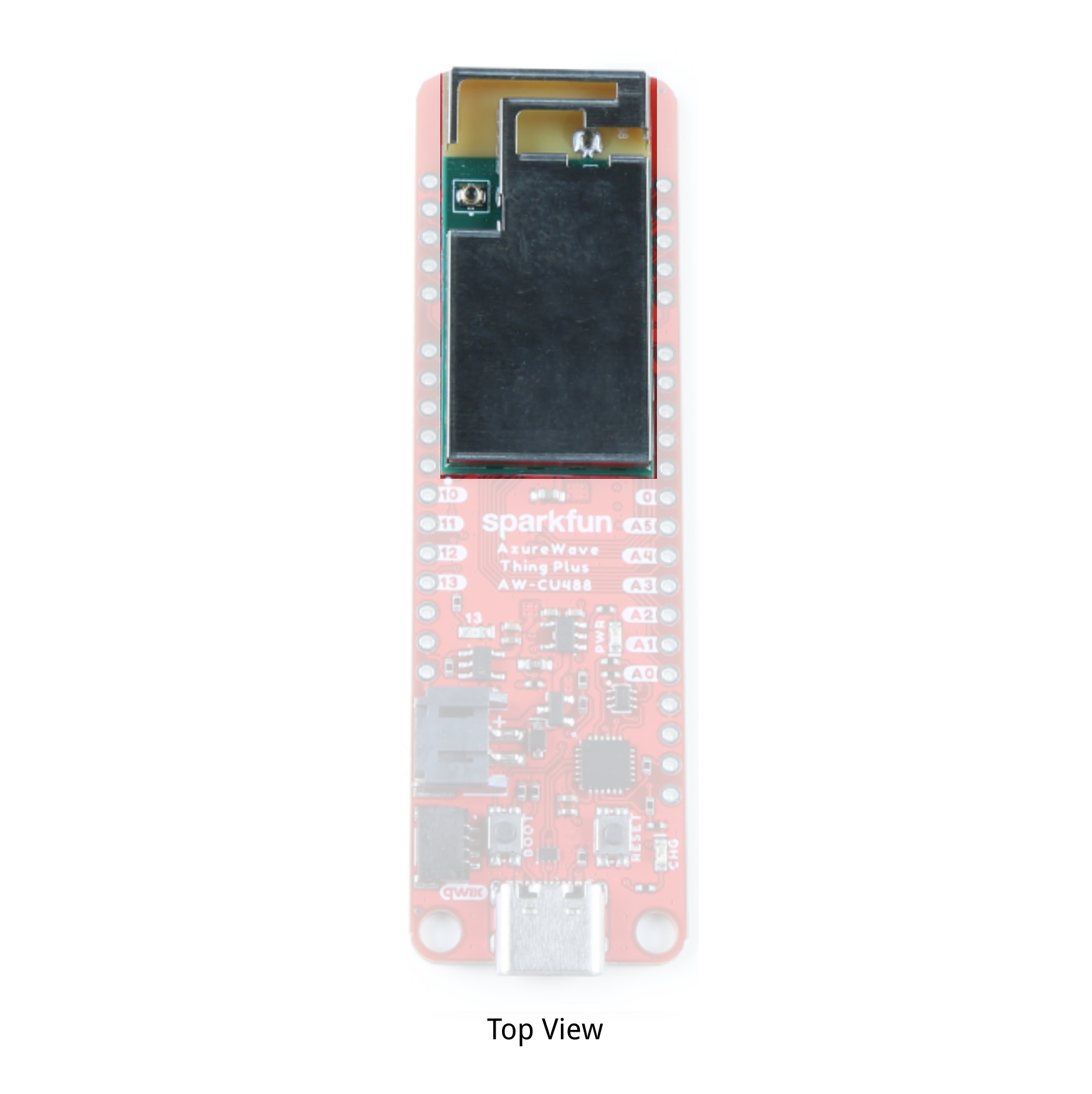
Hardware Overview
In this section, we will highlight the hardware and pins that are broken out on the AzureWave Thing Plus (AW-CU488). For more information, check out our Resources and Going Further for more information on the AzureWave AW-CU488 module or the Realtek RTL8721DM that is contained within the module.
GPIO
The AzureWave Thing Plus breaks out the GPIO pins to plated through hole pads on the edge of the board using the Thing Plus/ Feather Form Factor. Additional 1x5 pins are broken out along the extended part of the board.
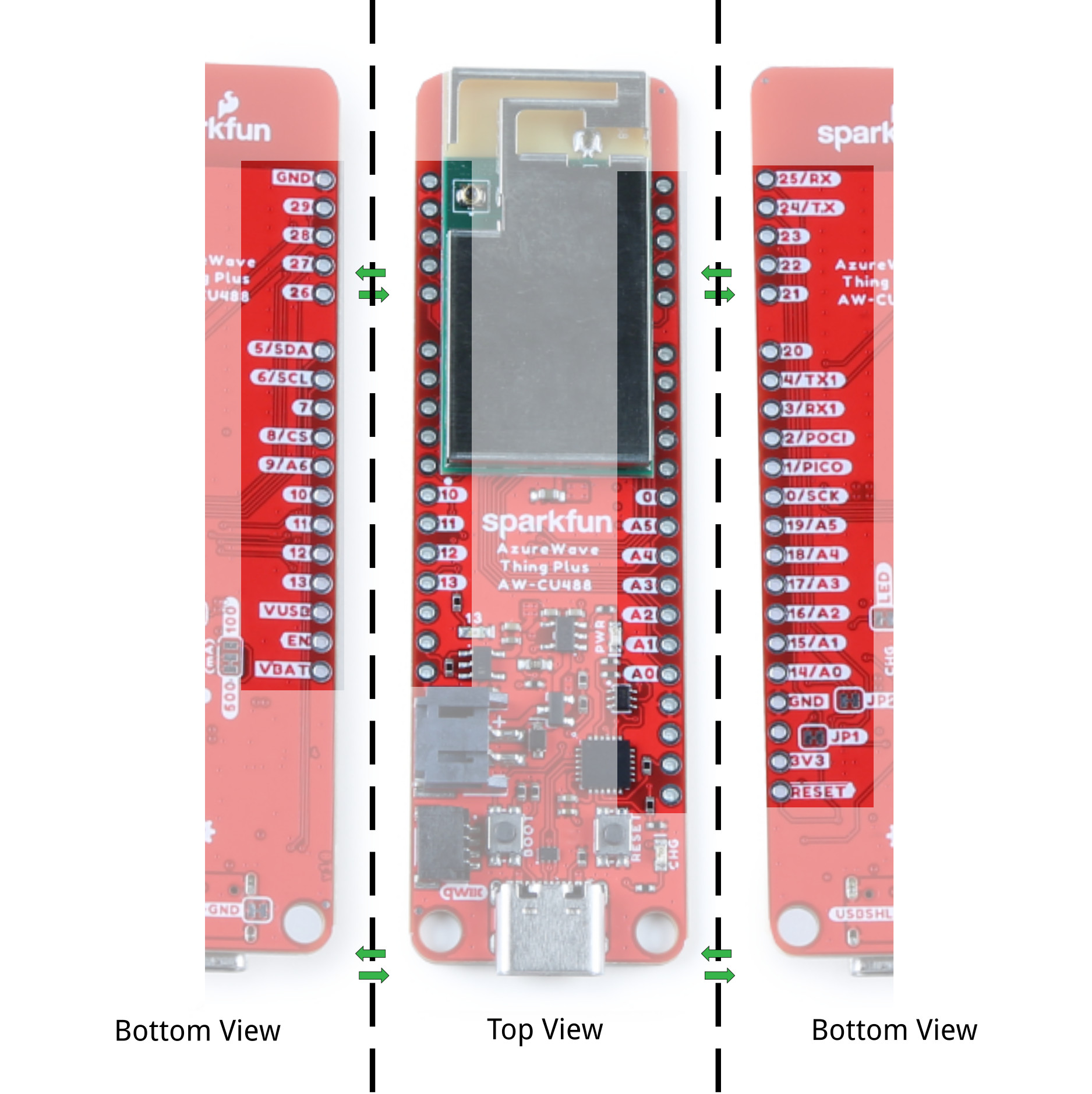
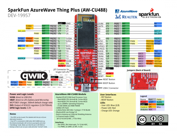
Note that the pin label might have additional functionality. Below is a graphical datasheet of the AzureWave Thing Plus (AW-CU488) that highlights the additional functionality.
27 is connected to GND when AW-CU488 boots up, the Arduino bootloader will not boot up properly and enter "test/debug" mode. Make sure that this pin is left HIGH at bootup so that it can run your code and enter "normal" mode.
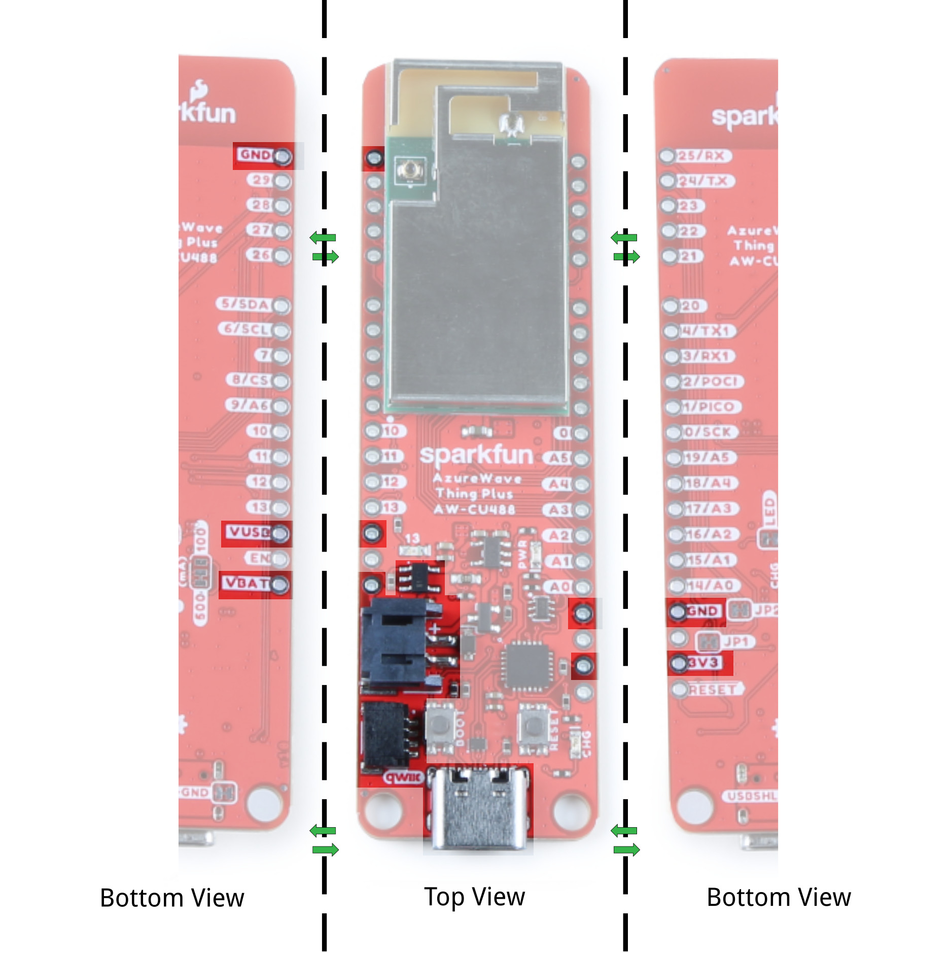
Power
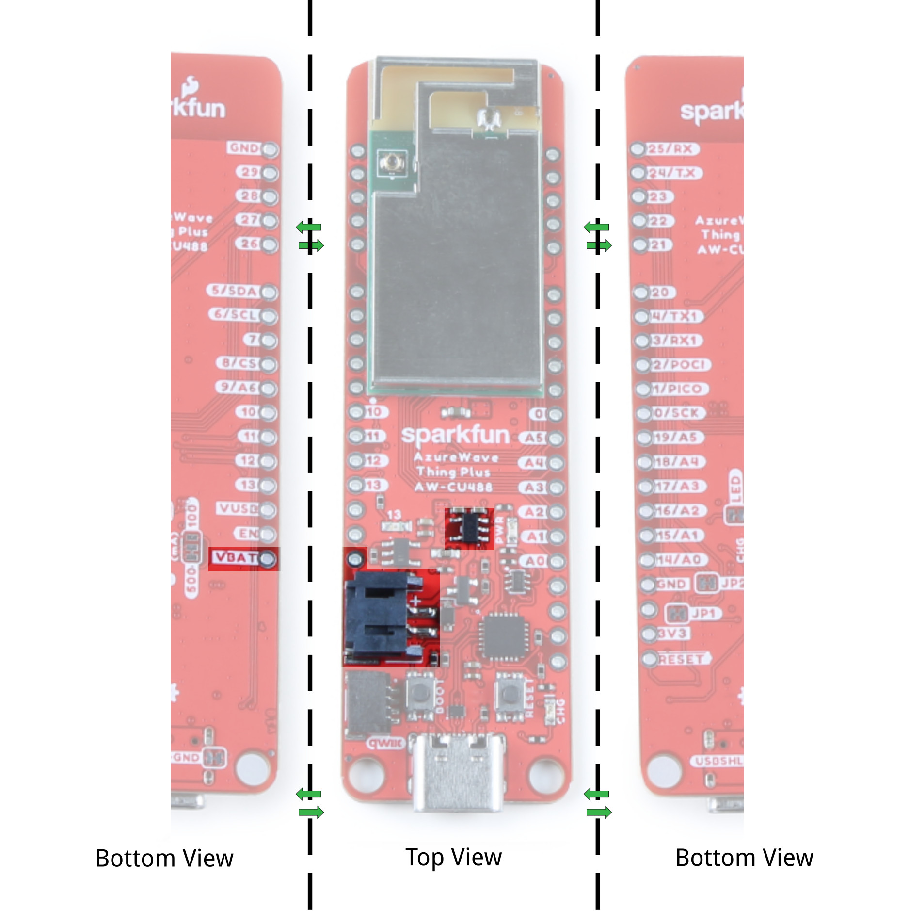
There are a variety of power and power-related nets broken out to connectors and through hole pads. Power is regulated down to 3.3V for the AW-CU488 so the logic level is 3.3V for the I/O.
- VBUS: The VBUS net is connected to the USB Type C connector and the VBUS PTH. You can use 5V from a USB port by connecting to the USB Type C connector or connecting power to the VBUS PTH. Make sure that power you provide to this pin does not exceed 6 volts. Power is regulated down with the XC6222 3.3V/700mA voltage regulator. The USB Type C connector is also used to upload code to your processor, send serial data to a terminal window, or charging the LiPo battery. Of course for portable power, you could connect a USB battery as an alternative to using a LiPo battery.
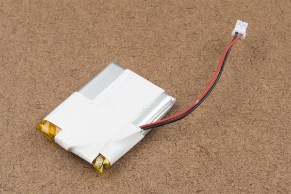
- VBAT: The VBAT net is connected to the 2-pin JST connector, VBAT PTH, and the AW-CU488's VBAT MEAS pin. For portable applications, you can connect a nominal 3.7V single cell, LiPo battery to the 2-pin JST connector. This pin is also connected to the MCP73831 charge IC to safely charge the LiPo battery to its maximum voltage of about 4.2V. We recommend connecting only LiPo batteries to the VBAT net to power the board. Of course, you can power a separate device through the VBAT PTH pin. Power is regulated down with the XC6222 3.3V/700mA voltage regulator.
- 3V3: The 3.3V net is labeled as 3V3. You can apply power to the board if you have a regulated voltage of 3.3V. Otherwise, you could power a separate device through the 3V3 PTH pin. This is also connected to the Qwiic connector's 3.3V pin to power Qwiic enabled devices.
- GND: of course, is the common, ground voltage (0V reference) for the system.
LiPo Charge Circuit
The board includes the MCP73831 LiPo charger IC (the little black IC with 5 pins) to safely charge a single cell, LiPo battery. In this case, the charge rate is set to a default rate of 500mA. Cutting the trace in the back and adding a solder jumper between the middle pad and the pad labeled as 100mA will set the charge rate to 100mA. The on-board LED labeled as CHG can be used to get an indication of the charge status of your battery.
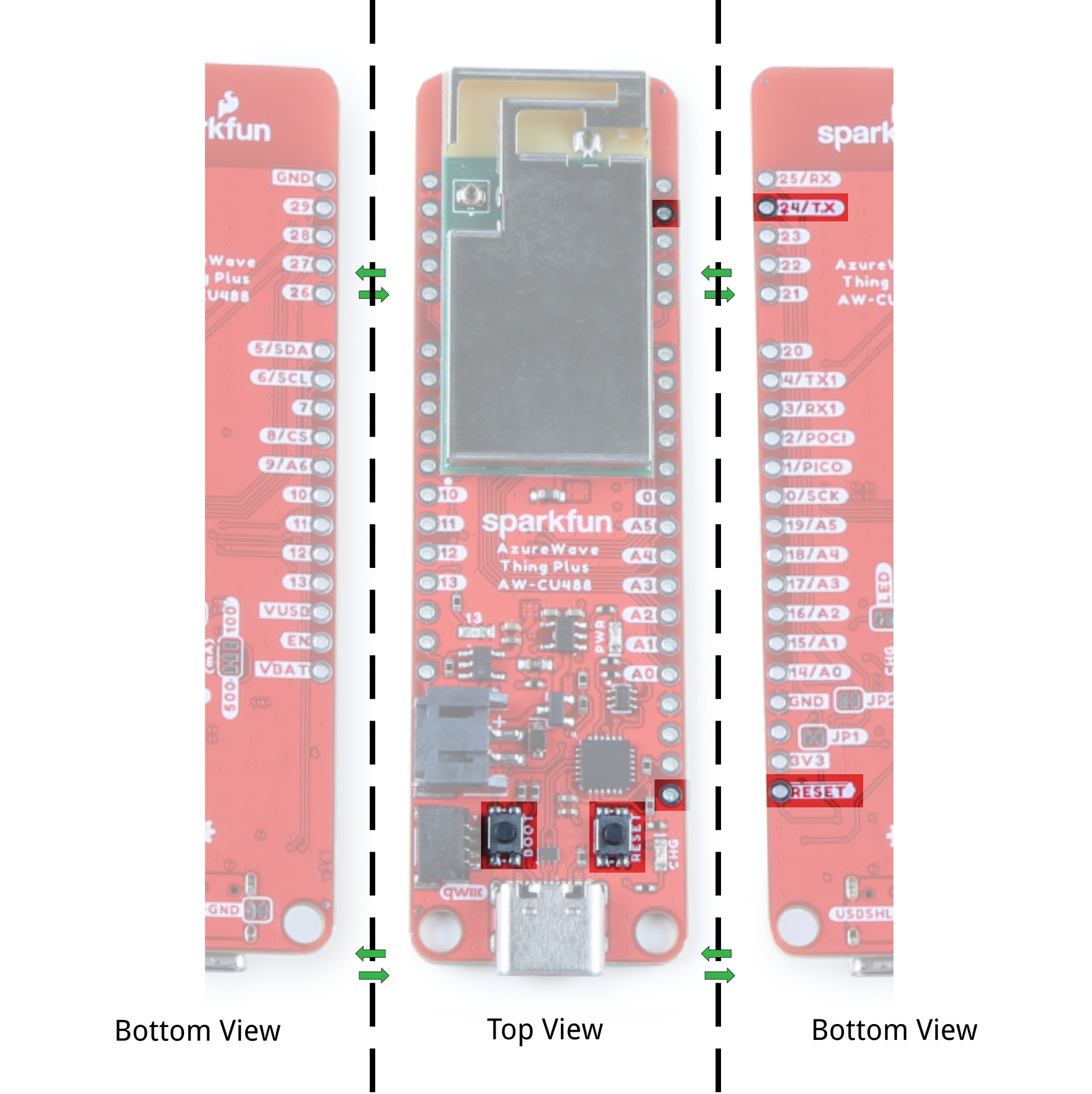
Reset and Boot Buttons
Each board includes a RESET and BOOT button. There is an additional reset PTH next to the reset button. Hit the reset button to restart the AW-CU488. To manually place the AW-CU488 into boot mode, hold down the BOOT button while pressing the RESET button momentarily and then release the BOOT button. As a side note, the BOOT button is also connected to pin 24 (TX). The datasheet refers to this pin as the CHIP_EN.
CP210X USB-to-Serial Converter
The board includes a USB-to-Serial converter. This is used for serial programming or communicating with a serial terminal. The CP210X's TX pin is connected to pin 25 (RX) while and RX pin is connected to pin 24 (TX).
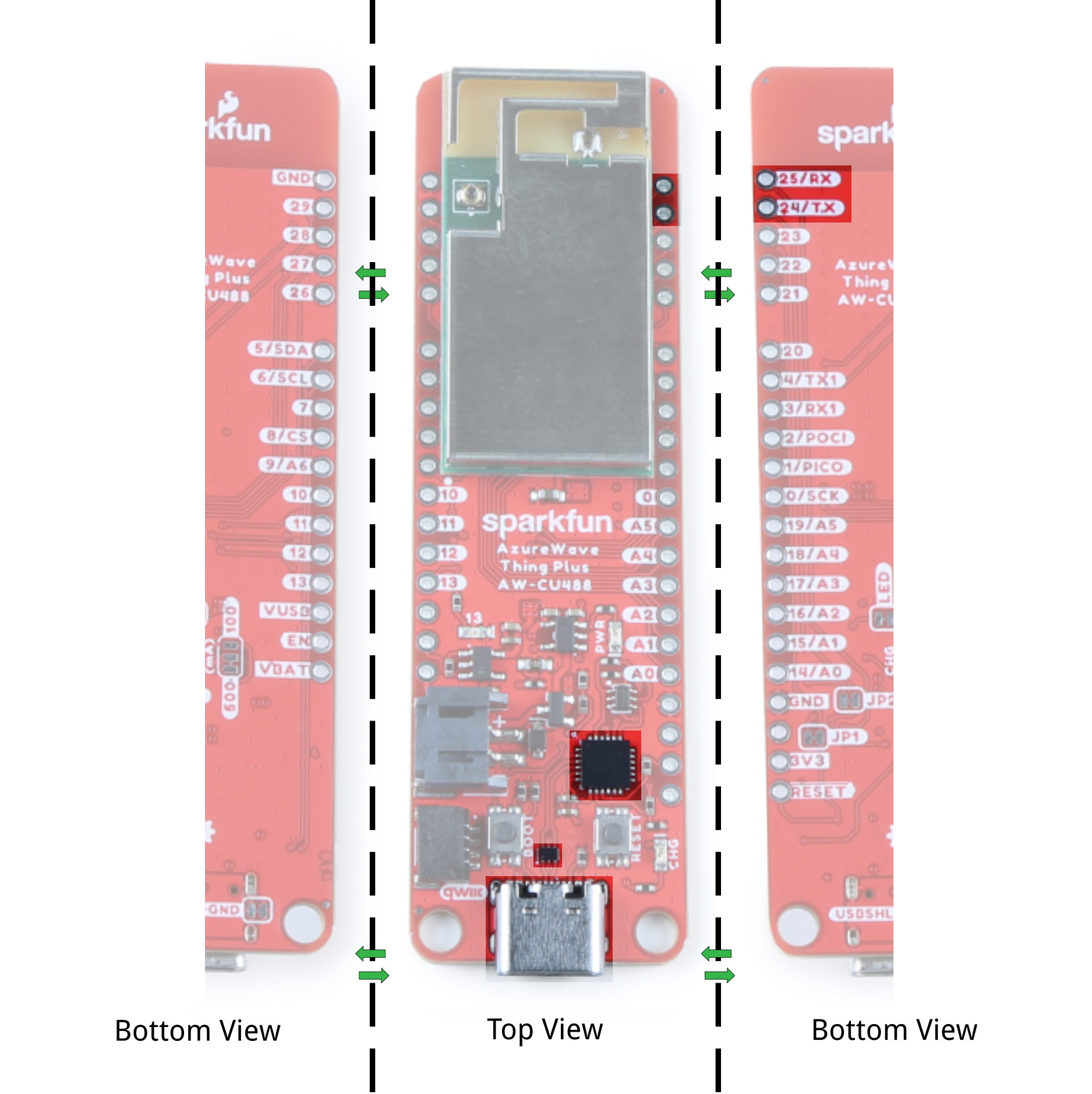
UART
There are two UART ports broken out. The primary UART is connected to pins 24 (TX) and 25 (RX). As stated earlier, these pins are connected to the BOOT button and USB-to-Serial converter. The secondary UART is connect to pins 4 (TX1) and 3 (RX1).

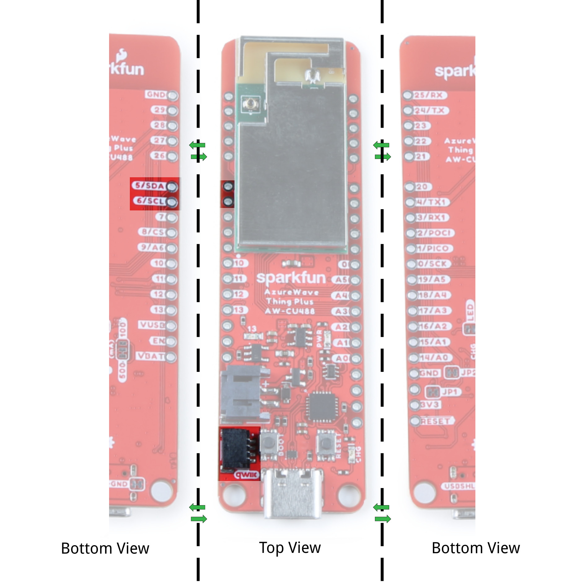
Qwiic and I2C
The board includes a horizontal Qwiic connector. These pins are connected to the primary I2C bus and 3.3V power allowing you to easily add a Qwiic-enabled device to your application. The I2C SCL pin is connected to 6. The I2C SDA is connected to 5.
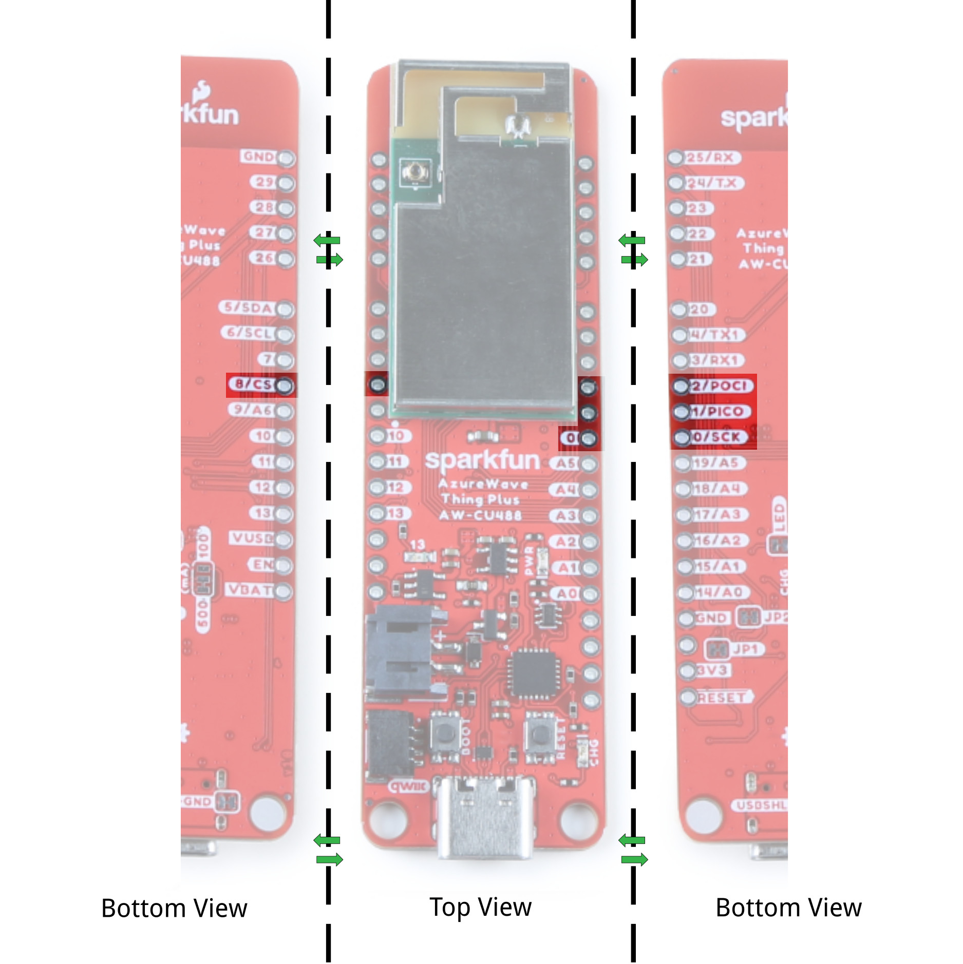
SPI
The primary SPI pins are on pin 0 (SCK), 1 (PICO), 2 (POCI), and 8 (CS).
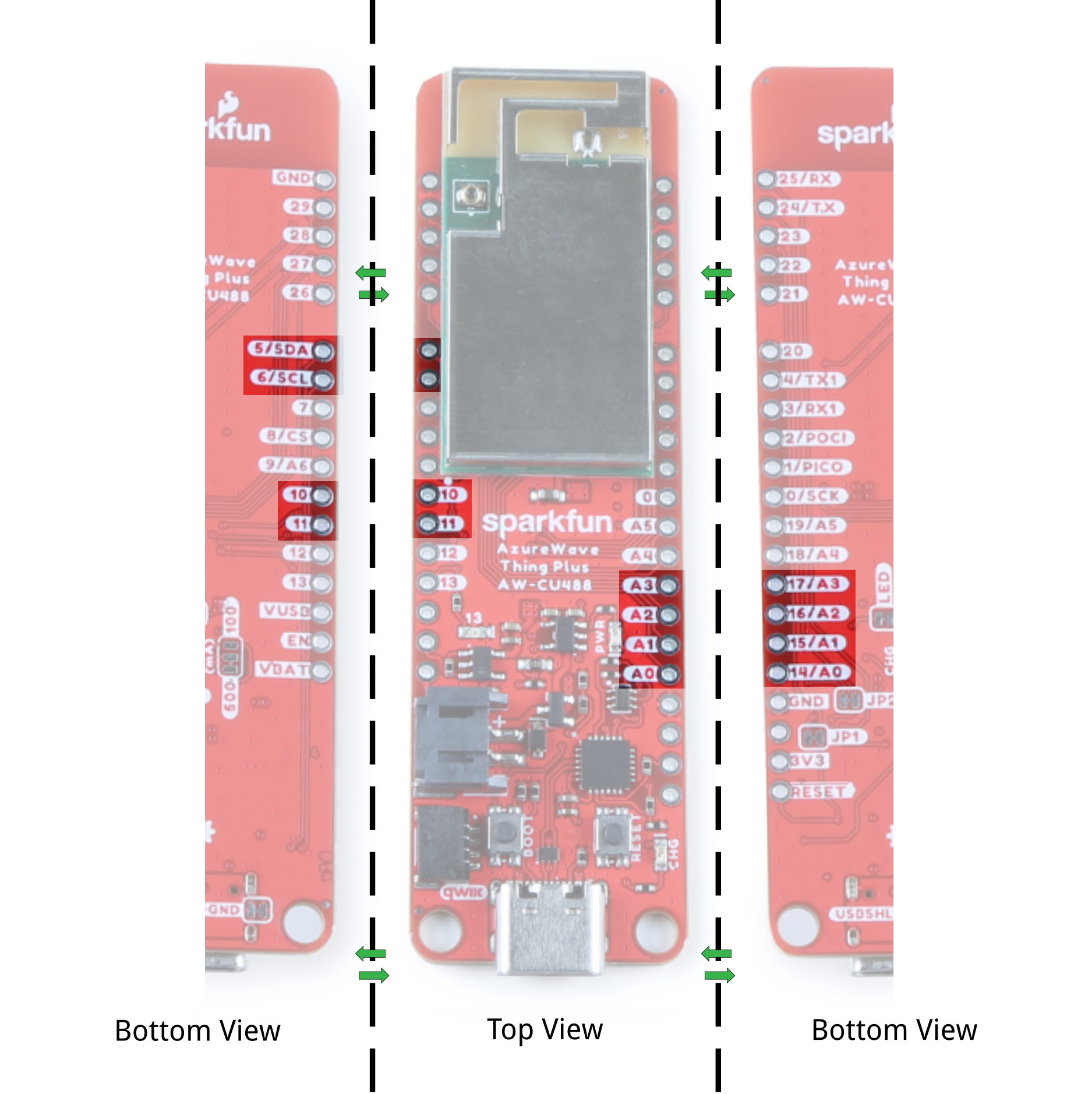
Analog
There are six analog pins available on pins 14 (A0), 15 (A1), 16 (A2), 17 (A3), 18 (A4), 19 (A5), and 9 (A6).

A0-A6) before including the library.
int analog_pin = A2;  //<=== Add this line before including Audio Codec library

#include "AudioCodec.h" //include Audio Codec Arduino library
#include "FFT.h"
Pulse Width Modulation (PWM)
The board includes 11x PWM pins. These can be found on the pinout table listed earlier in this section: 3, 4, 5, 6, 7, 10, 11, 14, 15, 17, and 26.
BOARD_RTL8721DM. For example, in the ServoSweep.ino file, they attach PWM pin 3 to servo object. You would need to adjust pin 3 to another PWM pin that is available on the AzureWave Thing Plus (AW-CU488).
.
.
.
#elif defined(BOARD_RTL8721DM)
// attaches the servo on PWM pin 3 to the servo object
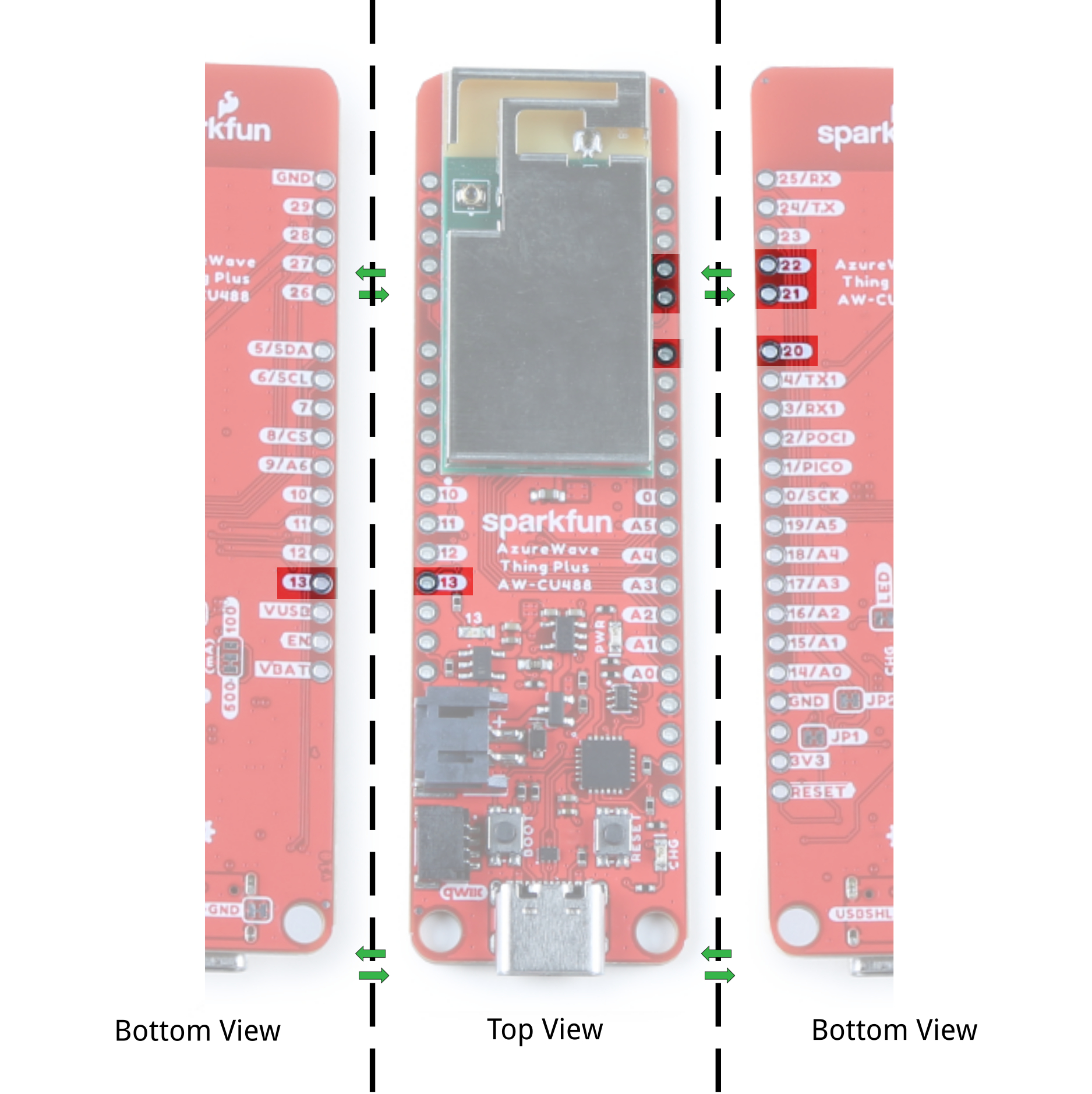
myservo.attach(3);Audio Codec Input Microphone and Analog Output Pins
Not labeled on the board is the microphone pins. Pin 21 is also the "MIC_BIAS" while the 22 is also the right microphone "MIC1_R." The analog output for the right and left speakers are on pin 13 (or "AOUTP_R") and pin 20 (or "AOUTP_L"). Note that the LED is tied to pin 13. We recommend using a different output pin for the LED if you decide to use this pin for the audio code.
Antenna
The AzureWave AW-CU488 module includes an internal shielding antenna. Note that the connector that looks similar to a "u.FL" connector is used for production testing and is not available to the user.
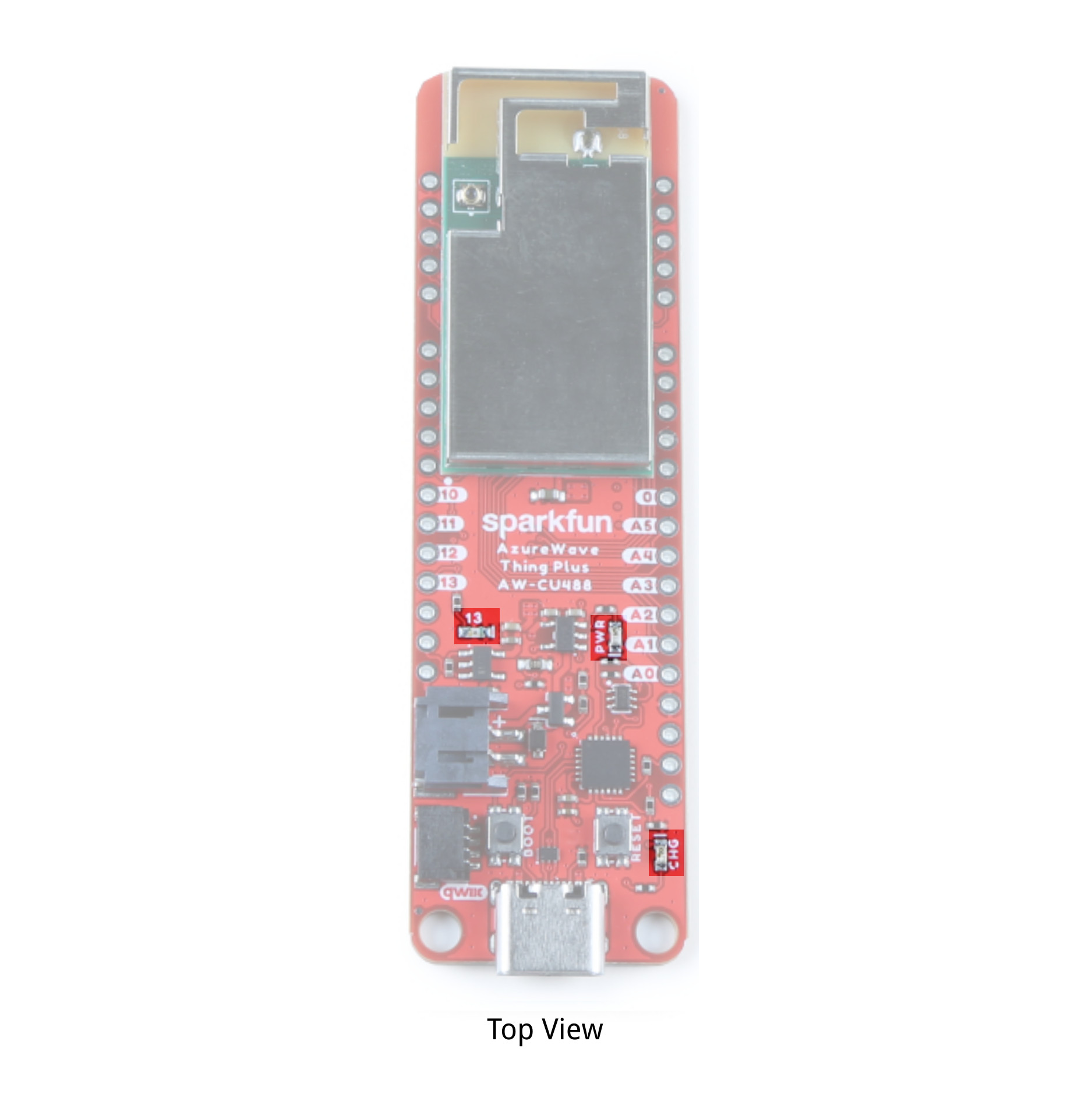
LEDs
The board includes three status LEDs.
- PWR - The PWR LED lights up to indicate when there is a 3.3V available after power is regulated down from the USB connector or LiPo battery. This can be disabled by cutting the jumper labeled as LED.
- 13 - The 13 LED can be configured by the user and is connected to pin 13. Note that this is also connected to the analog output "AOUTP_R". You will need to decide between using this pin for an LED or the analog output pin.
- CHG - The on-board yellow CHG LED can be used to get an indication of the charge status of your battery. Below is a table of other status indicators depending on the state of the charge IC.
| Charge State | LED status |
| No Battery | Floating (should be OFF, but may flicker) |
| Shutdown | Floating (should be OFF, but may flicker) |
| Charging | ON |
| Charge Complete | OFF |
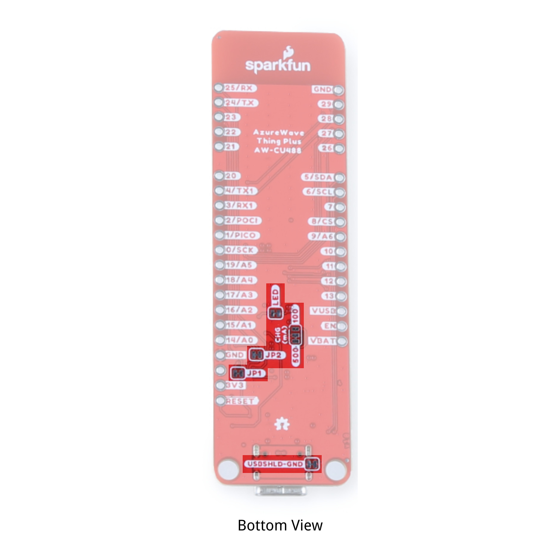
Jumpers
The following jumpers are included.
- CHG - This three way jumper sets the charge IC's charge rate. By default, it's connected to the 500mA. Cutting a trace and adding a solder jumper between the center pad and the pad labeled as 100mA will set the charge rate to 100mA
- USBSHLD-GND - This jumper connects the USB Type C connector's shield pin to GND. Cut this to isolate the USB Type C connector's shield pin. This is for advanced users that want to ground their board to their enclosure instead of the ground plane.
- LED - By default, this jumper is closed and located on the bottom of the board. Cut this trace to disable the power LED that is connected to 3.3V.
- JP1 - This jumper is connected to the auto-boot circuit by default. This is for advanced users that want to disable the auto-boot when uploading code. You will need to cut this jumper with JP2.
- JP2 - This jumper is connected to the auto-boot circuit by default. This is for advanced users that want to disable the auto-boot when uploading code. You will need to cut this jumper with JP1.
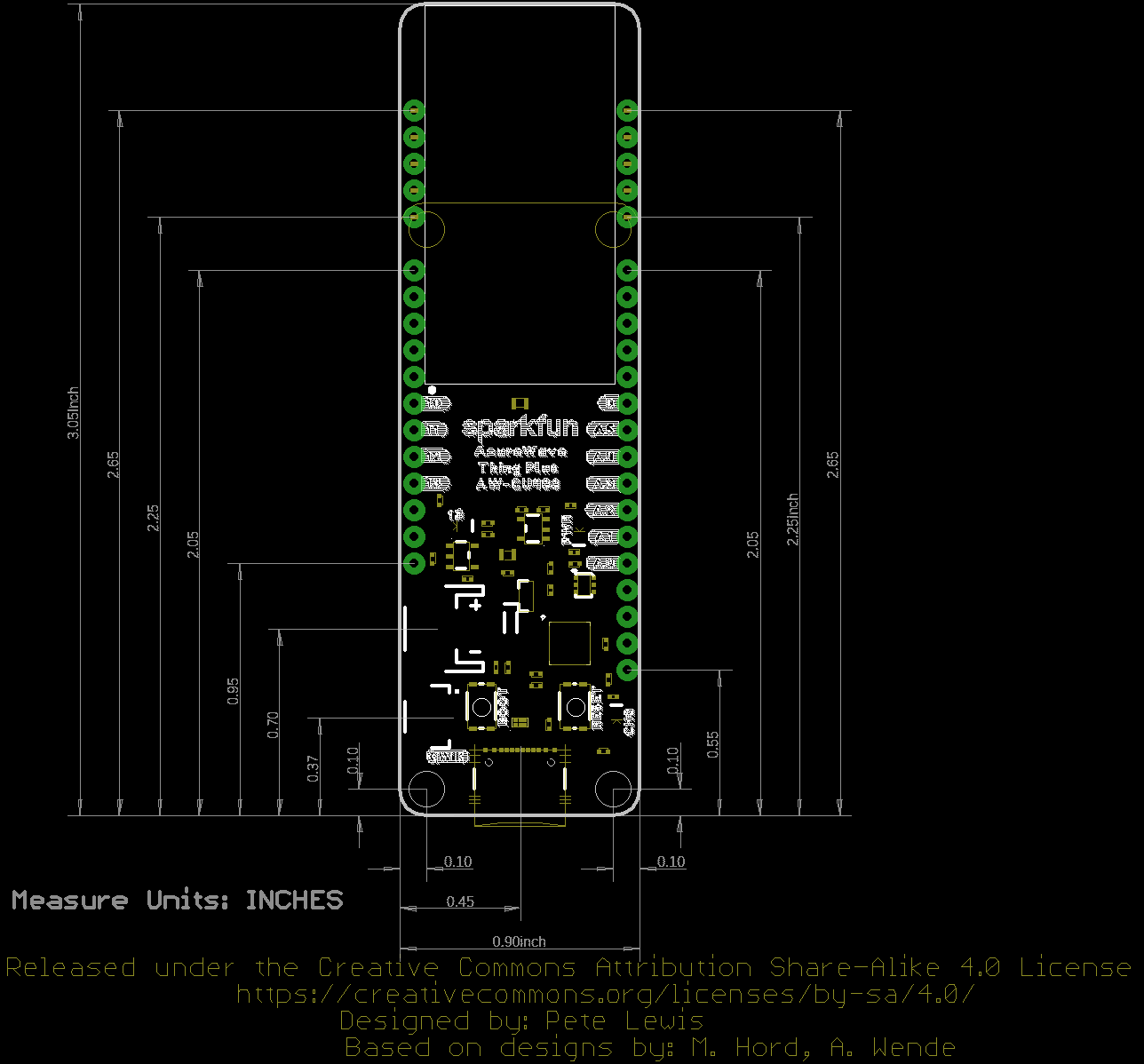
Board Dimensions
The board uses the Thing Plus footprint. Due to the size of the module, there are two mounting holes and the length of the board is extended to accommodate the size of the AW-CU488 module. Thus the board is about 3.05" x 0.90" (or 77.47 mm x 22.86 mm).