AzureWave Thing Plus (AW-CU488) Hookup Guide
 QCPete,
  bboyho
 Example 4a: Audio Codec - Input Fast Fourier Transform (FFT)
Required Materials
To follow along with this part of the tutorial, you will need the following materials. You may not need everything though depending on what you have. Add it to your cart, read through the guide, and adjust the cart as necessary.


Hardware Hookup
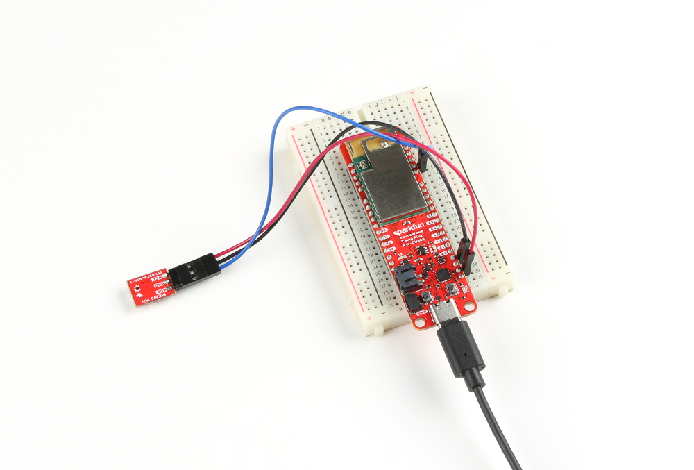
For the following example, you will need the following connection as shown in the Fritzing diagram.
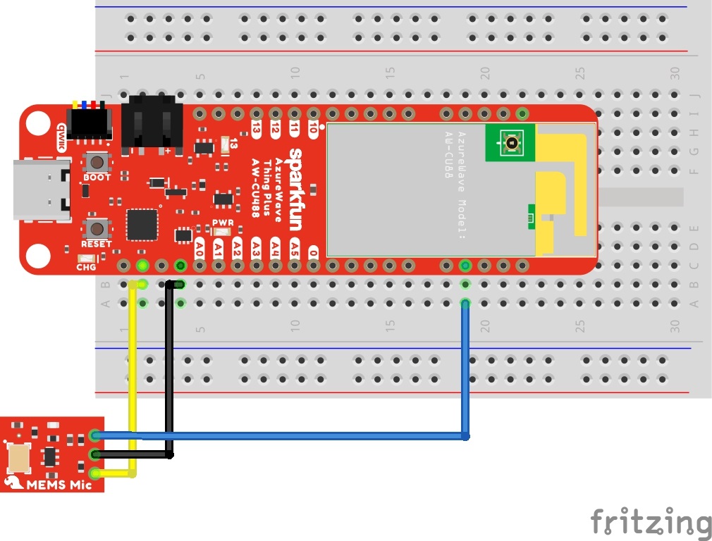
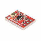
You will need to solder headers to the AzureWave Thing Plus (AW-CU488). Then solder headers on the MEMS microphone breakout. In this case, we soldered the straight headers at a right angle to connect a M/F jumper wire. Depending on your personal preference, you could also solder the headers on the MEMS microphone like the AzureWave Thing Plus (AW-CU488). Just make sure that the microphone input on the bottom side of the board faces away from the breadboard.
If you are using water soluble flux, make sure to clean off any flux residue remaining on the board. Make sure to be careful not to get any liquid into the MEMs microphone or the AW-CU488 module. Isopropyl alcohol and a Q-tip removes the water soluble flux pretty well. Then insert the board into the breadboard and connect the wires to the MEMS microphone. Finally, connect a USB C cable between the AzureWave Thing Plus (AW-CU488) and your computer's COM port.
Example Code
Let's upload the sketch to calculate the Fast Fourier Transform (FFT) of an audio signal. From the menu, select the following: File > Examples > Examples for AW_CU488 Thing Plus (RTL8721DM) | AmebaAudioCodec > InputFFT.
Or you can copy and paste the following code in the Arduino IDE. Select the correct board definition from the menu (in this case, Tools > Boards > AW-CU488 Thing Plus (RTL8721DM)). Then select the correct COM port that the board enumerated to (in this case, it was COM21). Hit upload button.
language:c
#include "AudioCodec.h"
#include "FFT.h"

#define SAMPLERATE 16000
#define SAMPLECOUNT 128

int16_t audio_buffer[SAMPLECOUNT] = {0};
float fft_buffer[SAMPLECOUNT/2] = {0};
uint16_t freq_bins[SAMPLECOUNT/2] = {0};
int i = 0;

FFT fft;

void setup() {
    Serial.begin(2000000);

    fft.setWindow(HANN, SAMPLECOUNT);
    fft.getFrequencyBins(freq_bins, SAMPLECOUNT, SAMPLERATE);

    for (i = 0; i < (SAMPLECOUNT/2); i++) {
        Serial.print(freq_bins[i]);
        Serial.print(" Hz | ");
    }
    Serial.println();

    Codec.setSampleRate(SAMPLERATE);
    Codec.begin(TRUE, FALSE);
}

void loop() {
    if(Codec.readAvaliable()) {
        Codec.readDataPage(audio_buffer, SAMPLECOUNT);    // read latest received data from buffer
        fft.calculate(audio_buffer, fft_buffer, SAMPLECOUNT);
        for (i = 0; i < (SAMPLECOUNT/2); i++) {
            if (fft_buffer[i] > 0.01) {
                Serial.print(fft_buffer[i],2);
                Serial.print(" | ");
            } else {
                Serial.print(" - |");
            }
        }
        Serial.println();
    }
    delay(1);
}
Open the Arduino Serial Monitor set to 2000000 will output the data similar to the output below. Each line will have a value in place for each frequency:
language:bash
0 Hz,125 Hz,250 Hz,375 Hz,500 Hz,625 Hz,750 Hz,875 Hz,1000 Hz,1125 Hz,1250 Hz,1375 Hz,1500 Hz,1625 Hz,1750 Hz,1875 Hz,2000 Hz,2125 Hz,2250 Hz,2375 Hz,2500 Hz,2625 Hz,2750 Hz,2875 Hz,3000 Hz,3125 Hz,3250 Hz,3375 Hz,3500 Hz,3625 Hz,3750 Hz,3875 Hz,4000 Hz,4125 Hz,4250 Hz,4375 Hz,4500 Hz,4625 Hz,4750 Hz,4875 Hz,5000 Hz,5125 Hz,5250 Hz,5375 Hz,5500 Hz,5625 Hz,5750 Hz,5875 Hz,6000 Hz,6125 Hz,6250 Hz,6375 Hz,6500 Hz,6625 Hz,6750 Hz,6875 Hz,7000 Hz,7125 Hz,7250 Hz,7375 Hz,7500 Hz,7625 Hz,7750 Hz,7875 Hz
Try blowing air across the input microphone or playing music from your smartphone. The FFT output will react to the input audio and split the signal into several bands. Better yet, try using a tone generator or playing a video that can generate an audio sample that reaches a desired frequency. The following video below is an audio sample that increases between 20Hz to 20kHz. Play the video below and watch the values for each frequency. You may need to adjust your speaker's volume. You will notice that the value will be the largest when the microphone hears a frequency that corresponds to the component. Adjacent components may be greater than 0 depending on your speaker's volume.
The example code breaks the audio sample into several components (it should be about half of the sample count, so 64 values for each line) which can make it hard to view through the Arduino Serial Monitor. Try outputting the data with comma separated values by replacing the spaces and | between each data with a comma '. If the value is less than 0.01, the value will be considered 0 instead of a -. Try scaling the values (i.e. multiplying the fft_buffer[i]*100) as well. This will help visualize the data through the Arduino Serial Plotter. Below is the modified example code with the changes described.
language:c
//modified inputFFT.ino for Comma Separated Values

#include "AudioCodec.h"
#include "FFT.h"

#define SAMPLERATE 16000
#define SAMPLECOUNT 128

int16_t audio_buffer[SAMPLECOUNT] = {0};
float fft_buffer[SAMPLECOUNT/2] = {0};
uint16_t freq_bins[SAMPLECOUNT/2] = {0};
int i = 0;

FFT fft;

void setup() {
    Serial.begin(2000000);

    fft.setWindow(HANN, SAMPLECOUNT);
    fft.getFrequencyBins(freq_bins, SAMPLECOUNT, SAMPLERATE);

    for (i = 0; i < (SAMPLECOUNT/2); i++) {
        //
        Serial.print(freq_bins[i]);
        Serial.print(" Hz");
        Serial.print(","); //comma separated value (CSV)
        //Serial.print(" | ");
    }
    Serial.println();

    Codec.setSampleRate(SAMPLERATE);
    Codec.begin(TRUE, FALSE);
}

void loop() {
    if(Codec.readAvaliable()) {
        Codec.readDataPage(audio_buffer, SAMPLECOUNT);    // read latest received data from buffer
        fft.calculate(audio_buffer, fft_buffer, SAMPLECOUNT);
        for (i = 0; i < (SAMPLECOUNT/2); i++) {
            if (fft_buffer[i] > 0.01) {
                // multiply the component by 100 so we can see the the value better in the Arduino Serial Plotter
                Serial.print(fft_buffer[i]*100,2);
                Serial.print(","); //comma separated value (CSV)
                //Serial.print(" | ");
            } else {
                Serial.print(0);
                Serial.print(","); //comma separated value (CSV)
                //Serial.print(" - |");
            }
        }
        Serial.println();
    }
    delay(1);
}
Try adjusting the code further and mapping the values to a PWM pin to turn on an LED when the audio reaches a certain frequency!