SparkFun Inventor's Kit for micro:bit Experiment Guide
 D___Run___,
  bboyho
 Experiment 8: Using a Servo Motor
Introduction
This experiment is your introduction to the servo motor, which is a smart motor that you can tell to rotate to a specific angular location. You will program it to rotate to a series of locations, then sweep across its full range of motion, and then repeat.
Parts Needed
You will need the following parts:
- 1x micro:bit
- 1x Micro B USB Cable
- 1x micro:bit Breakout (with Headers)
- 1x Breadboard
- 5x Jumper Wires
- 1x Servo
Didn't Get the SIK for micro:bit?
If you are conducting this experiment and didn't get the Inventor's Kit, we suggest using these parts:


Suggested Reading
Before continuing with this experiment, we recommend you be familiar with the concepts in the following tutorial:
Pulse Width Modulation
Hobby Servo Tutorial
Introducing the Servo Motor
Unlike the action of most motors that continuously rotate, a servo motor can rotate to and hold a specific angle until it is told to rotate to a different angle. You can control the angle of the servo by sending it a PWM (Pulse Width Modulation) pulse train; the PWM signal is mapped to a specific angle from 0 to 180 degrees.

Inside of the servo there is a gearbox connected to a motor that drives the shaft. There is also a potentiometer that gives feedback on the rotational position of the servo, which is then compared to the incoming PWM signal. The servo adjusts accordingly to match the two signals.
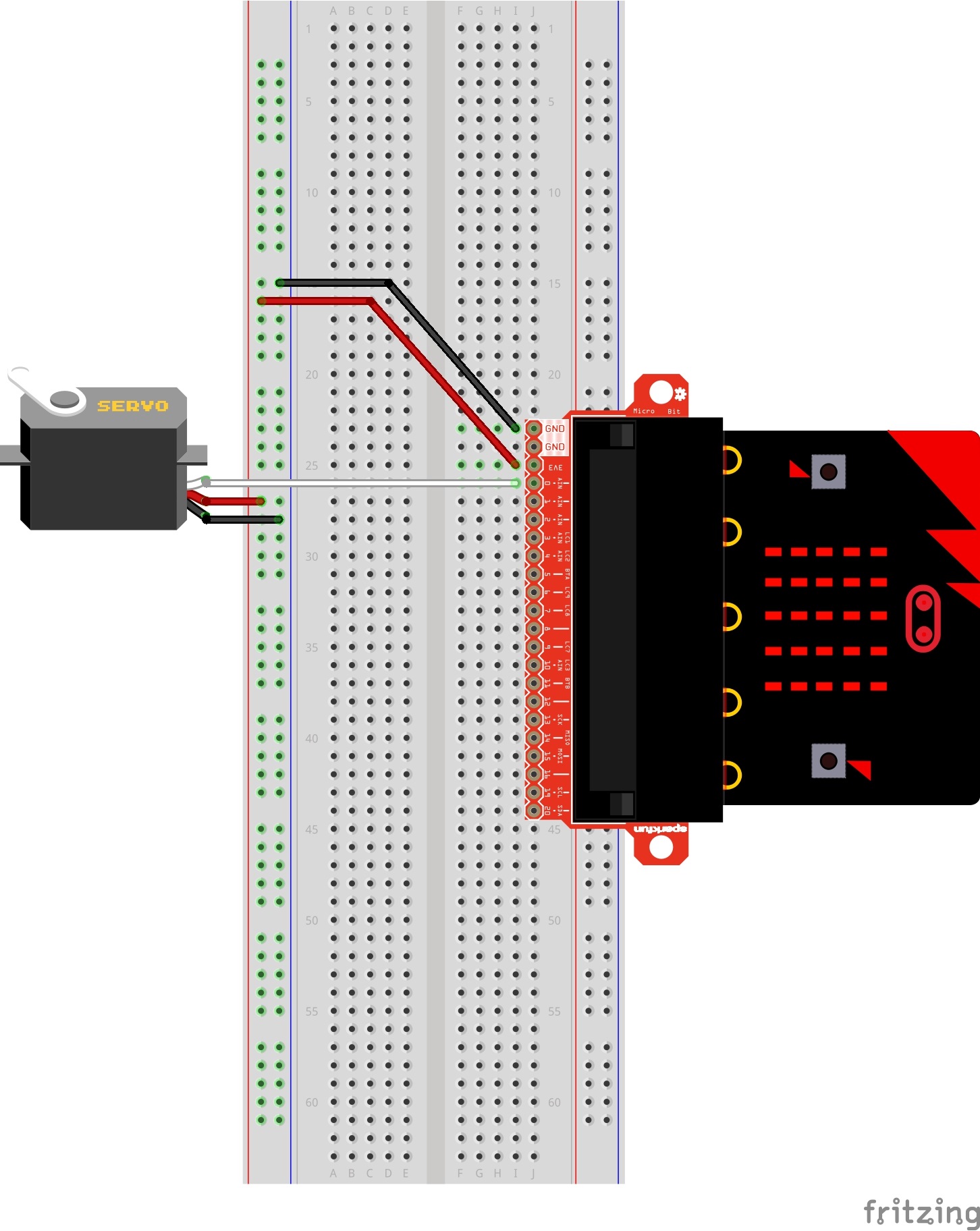
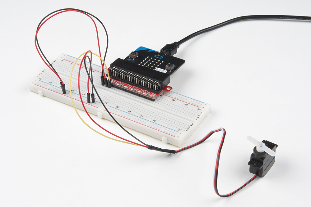
In this experiment, the servo is powered through 3.3 volts on the red wire and ground on the black wire; the white wire is connected to pin P0.
Hardware Hookup
Ready to start hooking everything up? Check out the wiring diagram below to see how everything is connected.
| Polarized Components | Pay special attention to the component’s markings indicating how to place it on the breadboard. Polarized components can only be connected to a circuit in one direction. |
Connect 3x jumper wires to the female 3-pin header on the servo. This will make it easier to breadboard the servo.
Wiring Diagram for the Experiment
Run Your Script
Either copy and paste, or re-create the following code into your own MakeCode editor by clicking the open icon in the upper right-hand corner of the editor window. You can also just download this example by clicking the download button in the lower right-hand corner of the code window.
Code to Note
Let's take a look at the code blocks in this experiment.
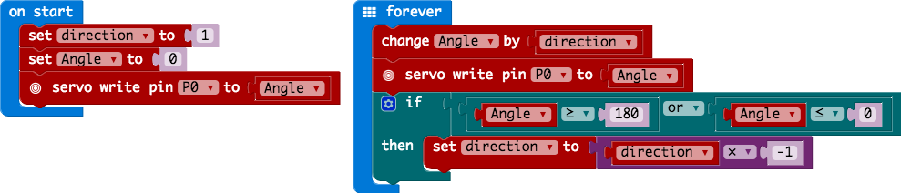
Set "Direction To"
In the On Start block we set the direction variable to 1. This value will be toggled between 1 and -1 to determine the direction we want the servo to sweep.
Servo Write
We use the Servo Write block to control a servo connected to a specific pin to rotate to a specific angle we pass it in degrees. We use a variable we have labeled as degrees. You can use this command to just write any angle between 0 and 180 to a servo motor at any time, but do remember to add a small pause to make sure that you give it enough time to respond before moving to the next angle.
Change by
If you want to increment or decrement a given variable by a certain value, which is positive or negative, you use the Change by block. You can select the variable you want to change and then the value you want to increment by (positive value) or decrement by (negative value). We increment the angle by 1 degree using this block.
Set "Direction to Direction x -1"
To change the direction of the servo once it reaches 0 or 180, we do some fancy math to multiply the direction variable by -1 to toggle it from a positive value to a negative number or a negative number to a positive value. That way when we use the change by block, the number is positive or negative.
What You Should See
When powered up you should see the servo move to a single location (0 degrees) and then start to sweep to 180 degrees back and forth until you turn it off or tell it to go to a different angle.
Troubleshooting
Servo Not Twisting
Even with colored wires, it is still shockingly easy to plug a servo in backward. This might be the case.
Still Not Working
A mistake we made a time or two was simply forgetting to connect the power (red and black wires) to 3.3 volts and ground (GND).