SparkFun Inventor's Kit for micro:bit Experiment Guide
 D___Run___,
  bboyho
 Introduction to the SparkFun Inventor's Kit for micro:bit
The SparkFun Inventor's Kit for micro:bit Experiment Guide is your map for navigating the waters of beginning embedded electronics, robotics and citizen science using the micro:bit. This guide contains all the information you will need to explore the 12 circuits of the SparkFun Inventors Kit for micro:bit. At the center of this guide is one core philosophy --- that anyone can (and should) experiment with cutting-edge electronics in a fun and playful way without breaking the bank.
When you're done with this guide, you'll have the know-how to start creating your own projects and experiments. From building robots and game controllers to data logging, the world will be your oyster. Now enough talking --- let's start tinkering!

Included Materials
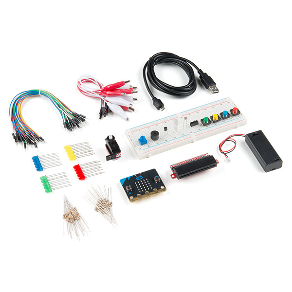
The SparkFun Inventor's Kit (SIK) for micro:bit includes the following:
- micro:bit --- The brains of the outfit with a bunch of onboard components. The version will vary depending on the kit or lab pack that you ordered.
- micro:bit Breakout (with Headers) --- Allows you to connect the micro:bit to the breadboard. The version will vary depending on the kit or lab pack that you ordered.
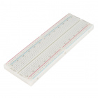
- Breadboard --- Excellent for making circuits and connections off the micro:bit. We included a full-sized breadboard to give you plenty of room.
- Small Servo --- Here is a simple, low-cost, high-quality servo for all your mechatronic needs.
- Piezo Buzzer --- BUZZZZ! Used to make different frequencies of sound.
- USB micro-B Cable --- This 6-foot cable provides you with a USB-A connector at the host end and standard B connector at the device end.
- Male-to-Male Jumper Wires --- These are high-quality wires that allow you to make connections with components on the breadboard.
- TMP36 Temperature Sensor - A sensor for detecting temperature changes.
- Photocell --- A sensor to detect ambient light. Perfect for detecting when a drawer is opened or when nighttime approaches.
- Tri-Color LED --- Because everyone loves a blinky.
- Red, Blue, Yellow, and Green LEDs --- Light-Emitting Diodes make great general indicators.
- Momentary Pushbutton Switch --- Go crazy with buttons.
- 10kΩ Trimpot --- Also known as a variable resistor, this is a device commonly used to control volume and contrast, and makes a great general user control input.
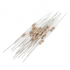
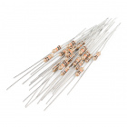
- 100Ω Resistors --- Great current-limiting resistors for LEDs, and strong pull-up resistors.
- 10kΩ Resistors --- These make excellent pull-ups, pull-downs and current limiters.
- 2x AAA Battery Pack --- AAA battery pack with the JST connector that fits the micro:bit
- Alligator Clip with Pigtail --- A great way to connect individual components on a breadboard to the micro:bit ring connectors.
| SparkFun Inventor's Kit micro:bit SKU |
Revision History |
|---|---|
| KIT-17362, LAB-17363 | - Switch to micro:bit V2. - Switch to Qwiic micro:bit breakout board (with headers). |
| KIT-15228, LAB-15229 | Switch to 2xAAA battery holder with a built-in switch. |
| KIT-14542, LAB-14301 | Initial release. |
750 mAh Alkaline Battery - AAA
PRT-09274What's that? You've already got a micro:bit but still want to follow along? We have options!
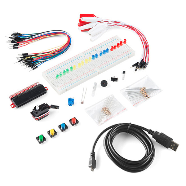
- Get the handy dandy SparkFun Inventor's Kit Bridge Pack for micro:bit, which contains all of the items in the SIK kit except for the micro:bit. You can get all the parts in one fell swoop and a nice red box to boot!
- Alternatively, you can pick and choose parts for individual experiments. This is a great option for folks who may already have some of the items in this tutorial just hanging around. Throughout this guide, we will provide links to the parts used for each circuit. Below is a wishlist for the parts used in the kit. Depending on what you have, you may not need everything on this list. Add it to your cart, read through the guide, and adjust the cart as necessary.
Suggested Reading
Before continuing with this guide, we recommend you be somewhat familiar with the concepts in the following tutorials:
- Voltage, Current, Resistance, and Ohm's Law --- The most basic concepts in electronics and electrical engineering. Get very familiar with these concepts, as they will be used throughout your electronics adventure.
- What is a Circuit? --- In this guide, we will be building a variety of circuits. Understanding what that means is vital to understanding the Inventor's Kit.
- How to Use a Breadboard --- First time working with a breadboard? Please check out this tutorial! It will help you understand why the breadboard is great for prototyping and how to use one.
What is a Circuit?
Voltage, Current, Resistance, and Ohm's Law
How to Use a Breadboard
Open Source!
All of our experiments and guides are licensed under the Creative Commons Attribution Share-Alike 4.0 Unported License. Feel free to remix and reuse our work. But please, share the love and give us attribution for our hard work!
To view a copy of this license visit this link, or write: Creative Commons, 171 Second Street, Suite 300, San Francisco, CA 94105, USA.
What is the micro:bit?
Introduction
The micro:bit is a pocket-sized computer that lets you get creative with digital technology. You can code, customize and control your micro:bit from anywhere! You can use your micro:bit for all sorts of unique creations, from robots to musical instruments and more. There are a few versions available. The first version was used throughout a majority of this tutorial. The revised micro:bit V2 was eventually released. Don't worry the overall functionality is the same, there's just a few extra features built into the micro:bit V2.
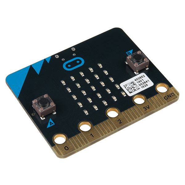
micro:bit Board
DEV-14208
The micro:bit is the most recent project by the British Broadcasting Corp. (BBC) in an effort to bring computer science education and STEM topics to every student in the United Kingdom. It is an open development board that works in sync with onboard hardware components to get you started down the path of programming hardware.
At half the size of a credit card, each board is equipped with a surprising amount of hardware, including 25 red LED lights that can flash messages. There are two programmable buttons that can be used to control games or pause and skip songs on a playlist. The micro:bit can even detect motion and tell you which direction you’re heading. It can also use Bluetooth Low Energy (BLE) to interact with other devices and the internet.
The micro:bit features an embedded compass and accelerometer, and mobile and web-based programming capabilities.The micro:bit v2 adds an onboard speaker and MEMS microphone, as well as a touch-sensitive logo. Both boards are compatible with a number of online code editors across a number of different languages. This guide will focus on MakeCode, a block- or JavaScript-based environment developed by Microsoft.
What is on the Board?
There are two versions of the BBC micro:bit and both have a lot to offer when it comes to onboard inputs and outputs. In fact, there are so many things packed onto these little boards that you would be hard pressed to really need anything else if you were looking at just exploring the basics of programming and hardware.
Front
On the front of the board there are a number of components that are pretty visible right off the bat!
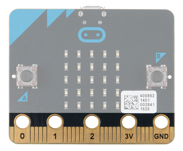
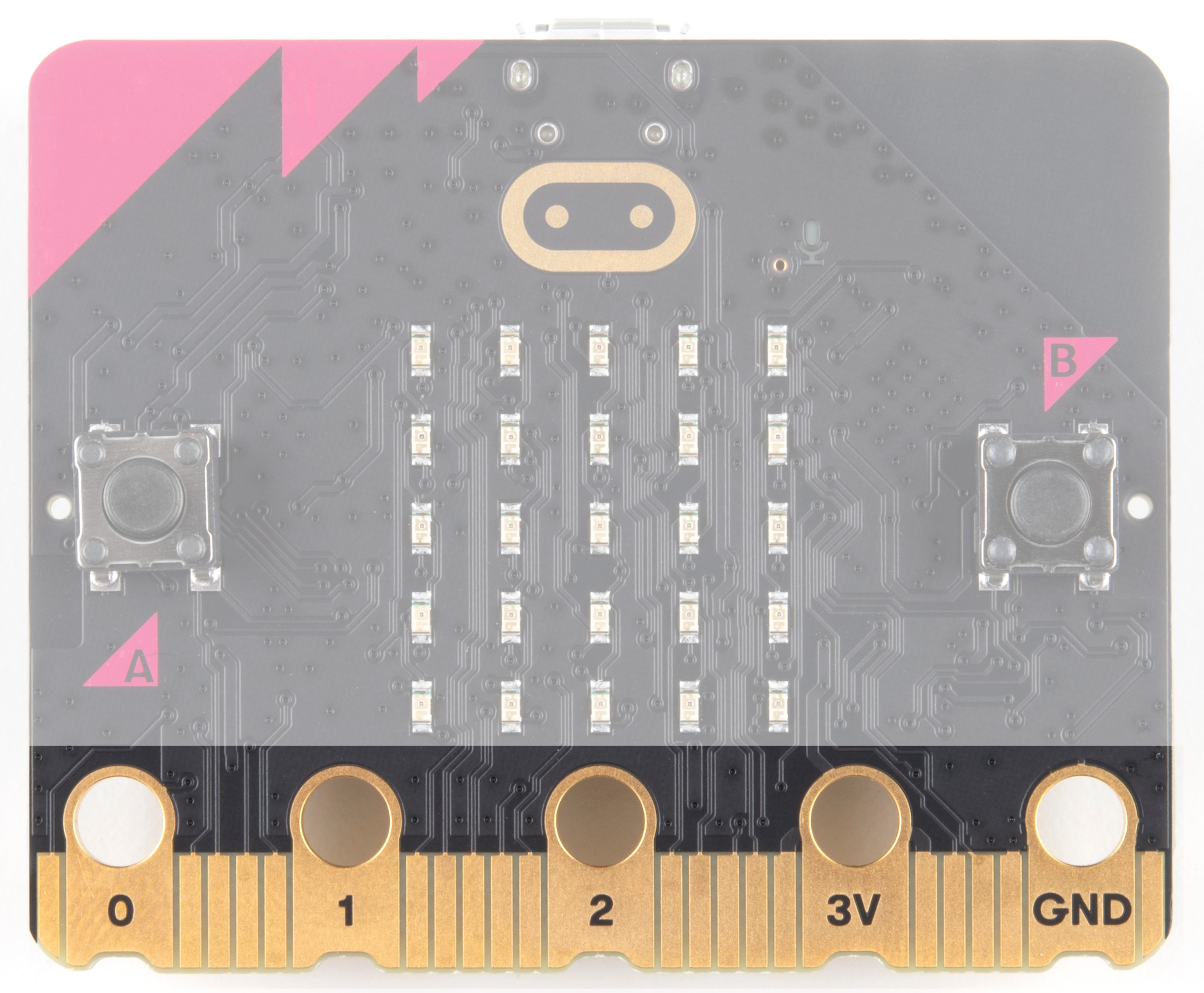
LED Array
The micro:bit has a 5x5 LED array that you can use as a tiny screen to draw on and display words, numbers and other information.
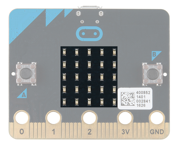 |
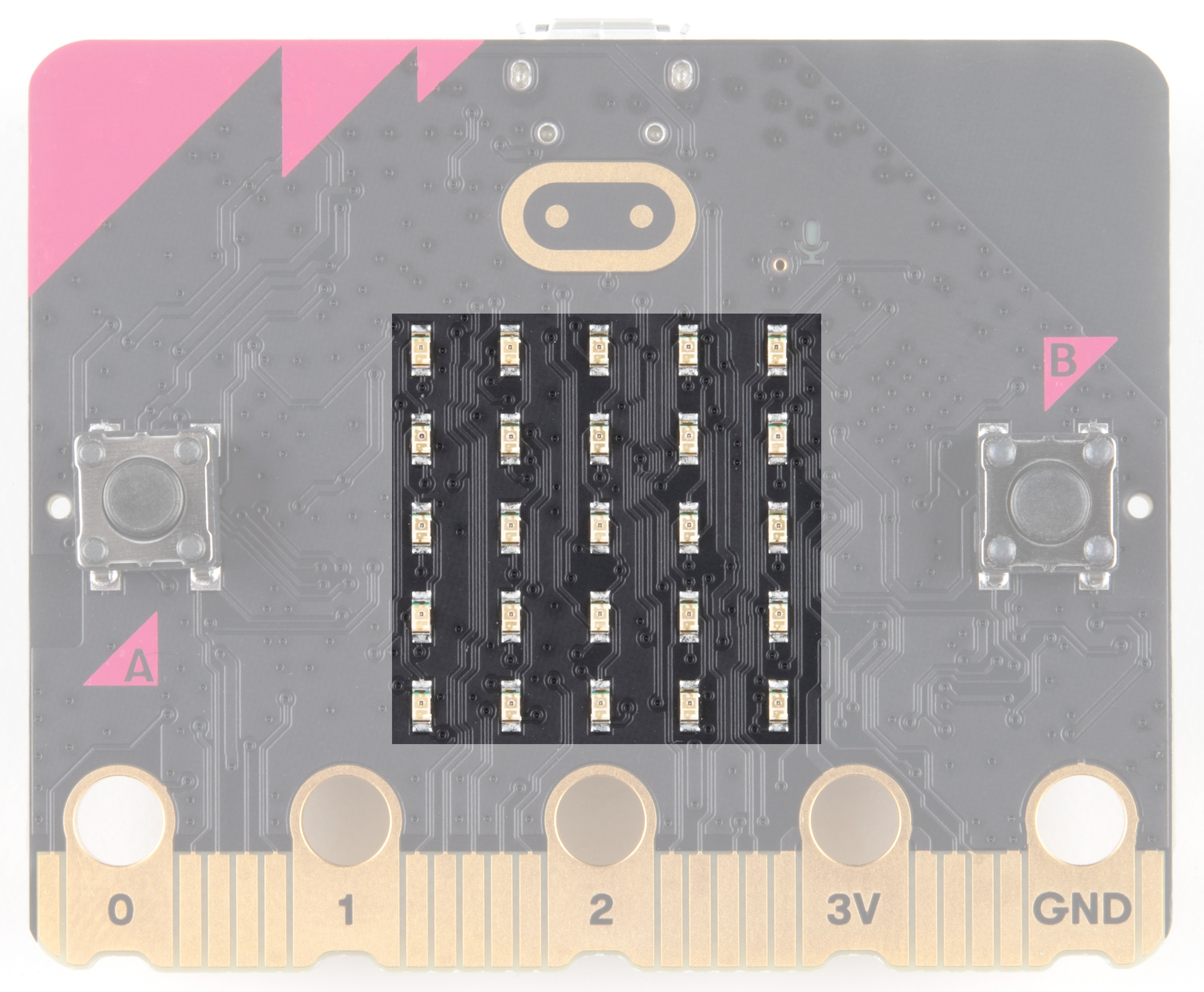 |
| LED Array on micro:bit | LED Array on micro:bit V2 |
A/B Buttons
Two buttons in all of their clicky glory: A is on the left, B is on the right, and both are prime for controlling a game of your design.
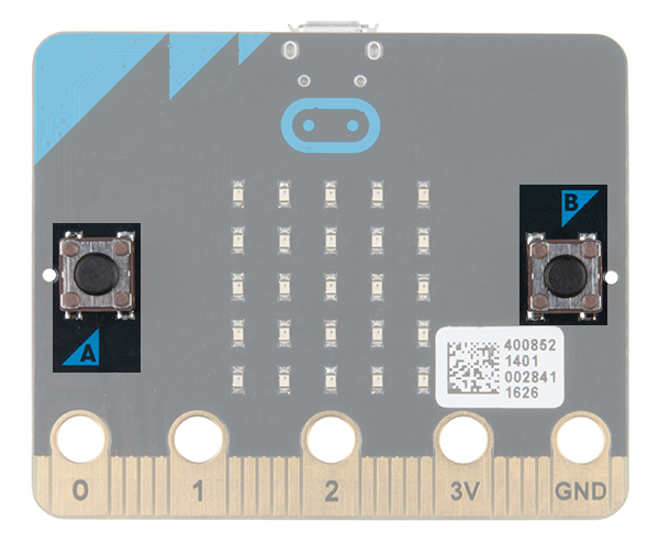 |
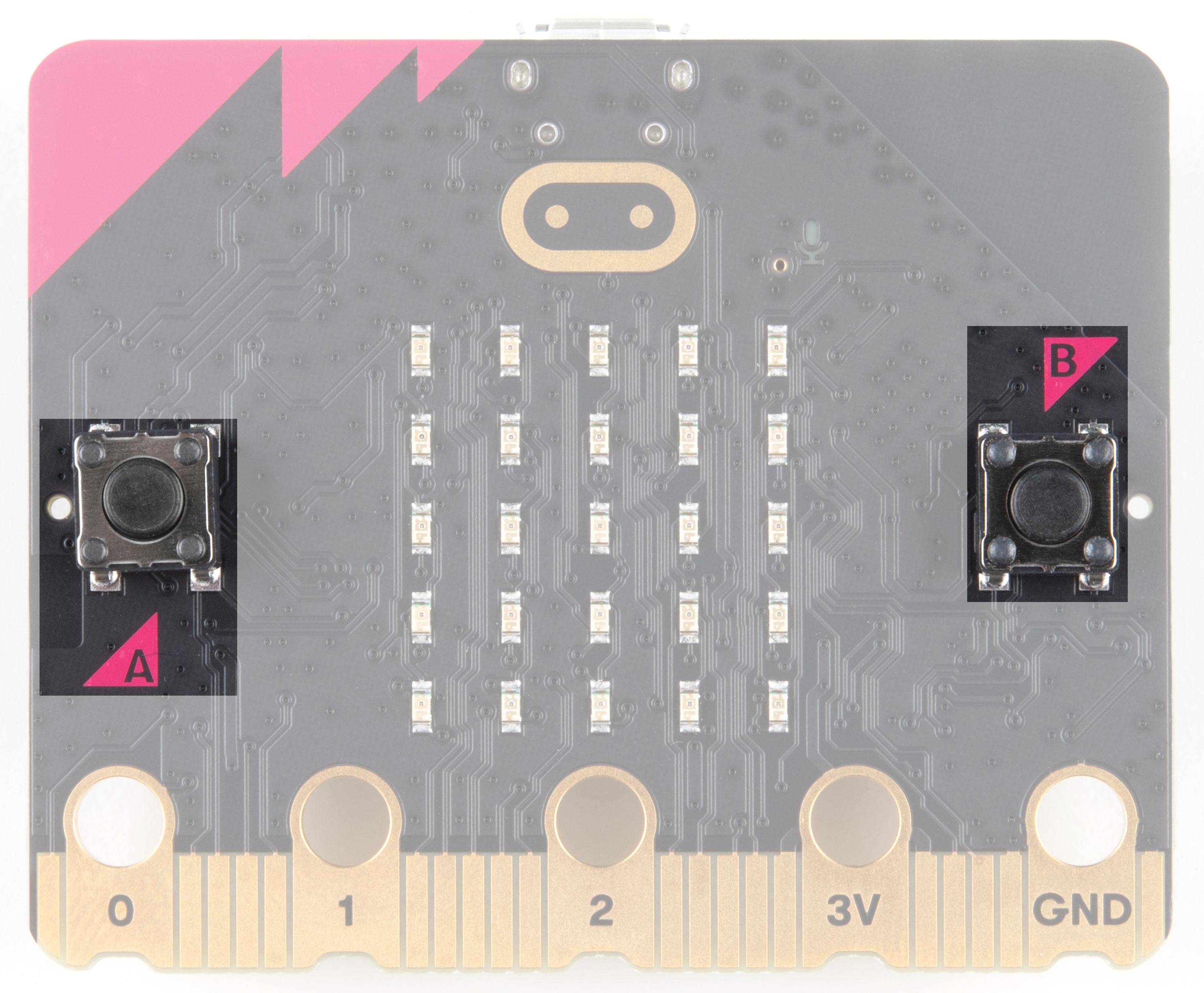 |
| A/B Buttons on micro:bit | A/B Buttons on micro:bit V2 |
Edge "Pins"
The gold tabs at the bottom of the board are for hooking up external components. The tabs with larger holes can be easily used with alligator clips to prototype things quickly! To access all the pins, you will need a board with an edge connector. For breadboard prototyping, you'll want the micro:bit breakout with headers. In micro:bit v2, you will also notice that they are notched for easier connection with alligator clips.
 |
 |
| Edge Pins on micro:bit | Edge Pins on micro:bit V2 |
 |
 |
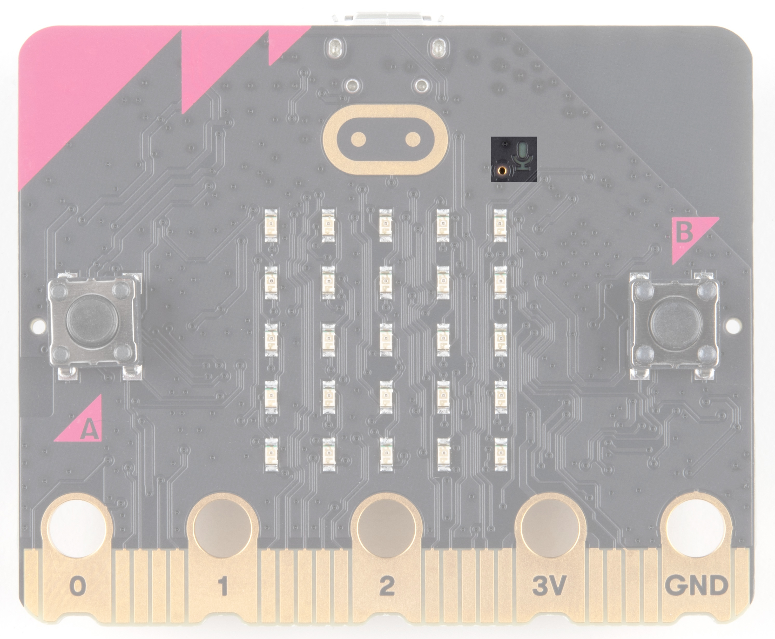
Light Sensor
A bit of a hidden gem. The LED array doubles as a light sensor!
|
|
| Light Sensor on micro:bit | Light Sensor on micro:bit V2 |
V2 Only - Microphone Input and LED Indicator
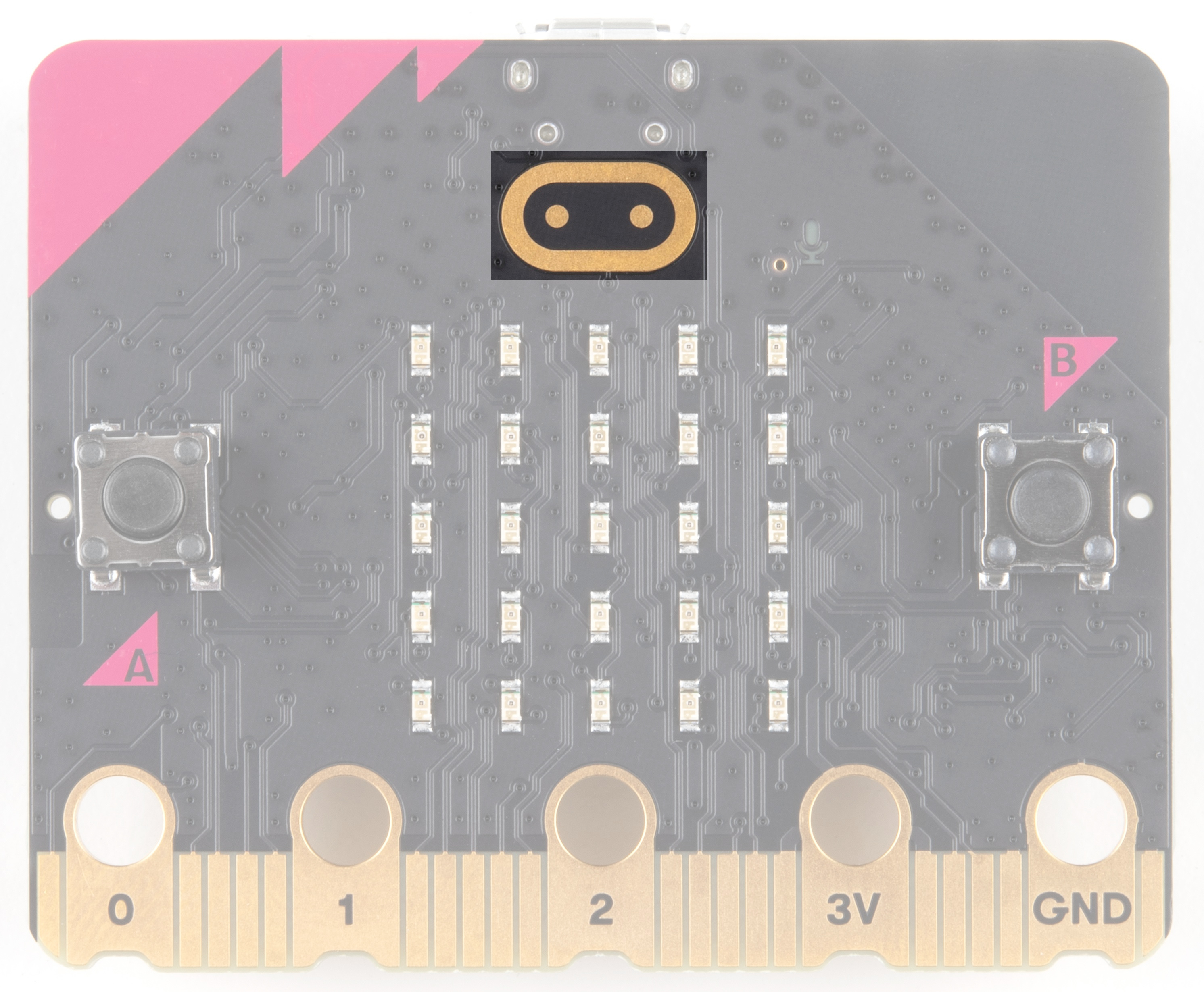
V2 Only - Touch Sensitive Logo
The gold logo is a capacitive touch sensor that works a bit like a touch screen on a mobile phone, measuring tiny changes in electricity.
Back
The back is where a lot of the magic happens. Check it out...
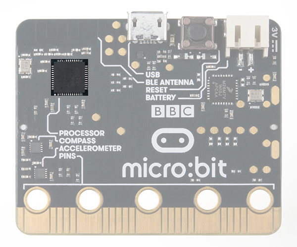
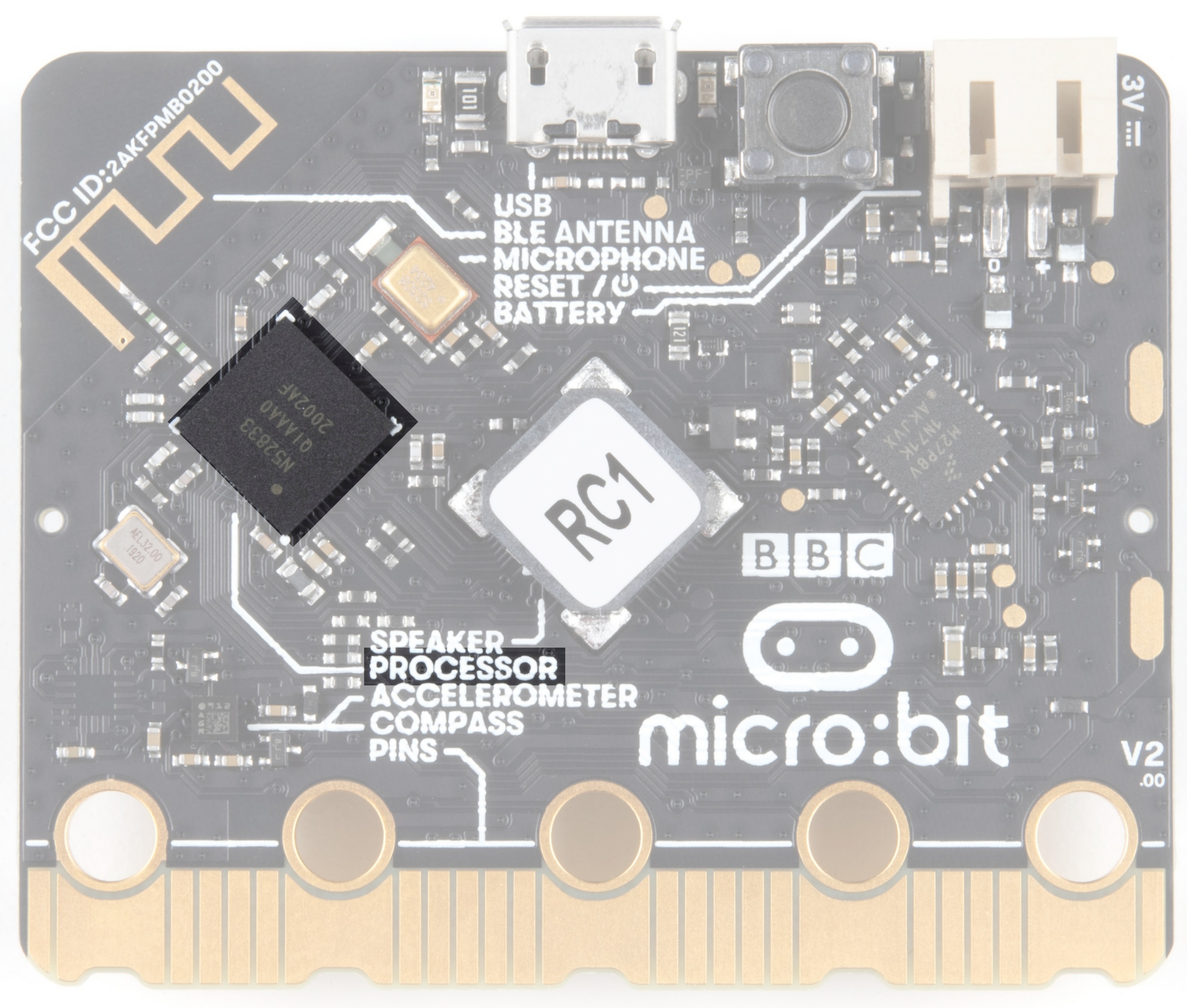
Microcontroller
The brains of the outfit.
The micro:bit is powered by a 16MHz ARM Cortex-M0 microcontroller with 256KB Flash and 16KB RAM.
The micro:bit v2 is powered by Nordic Semiconductor's nRF52833 chip - a 64MHz ARM Cortex-M4 microcontroller with FPU, 512KB Flash, and 128KB RAM.
 |
 |
| nRF51822 Processor on micro:bit | nRF52833 Processor on micro:bit V2 |
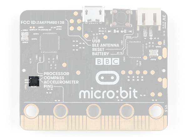
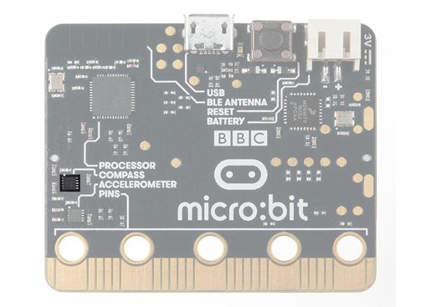
Accelerometer/Compass
The micro:bit has an onboard accelerometer that measures gravitational force, as well as a compass (a.k.a. a magnetometer) that can detect its orientation using Earth's magnetic field.
 |
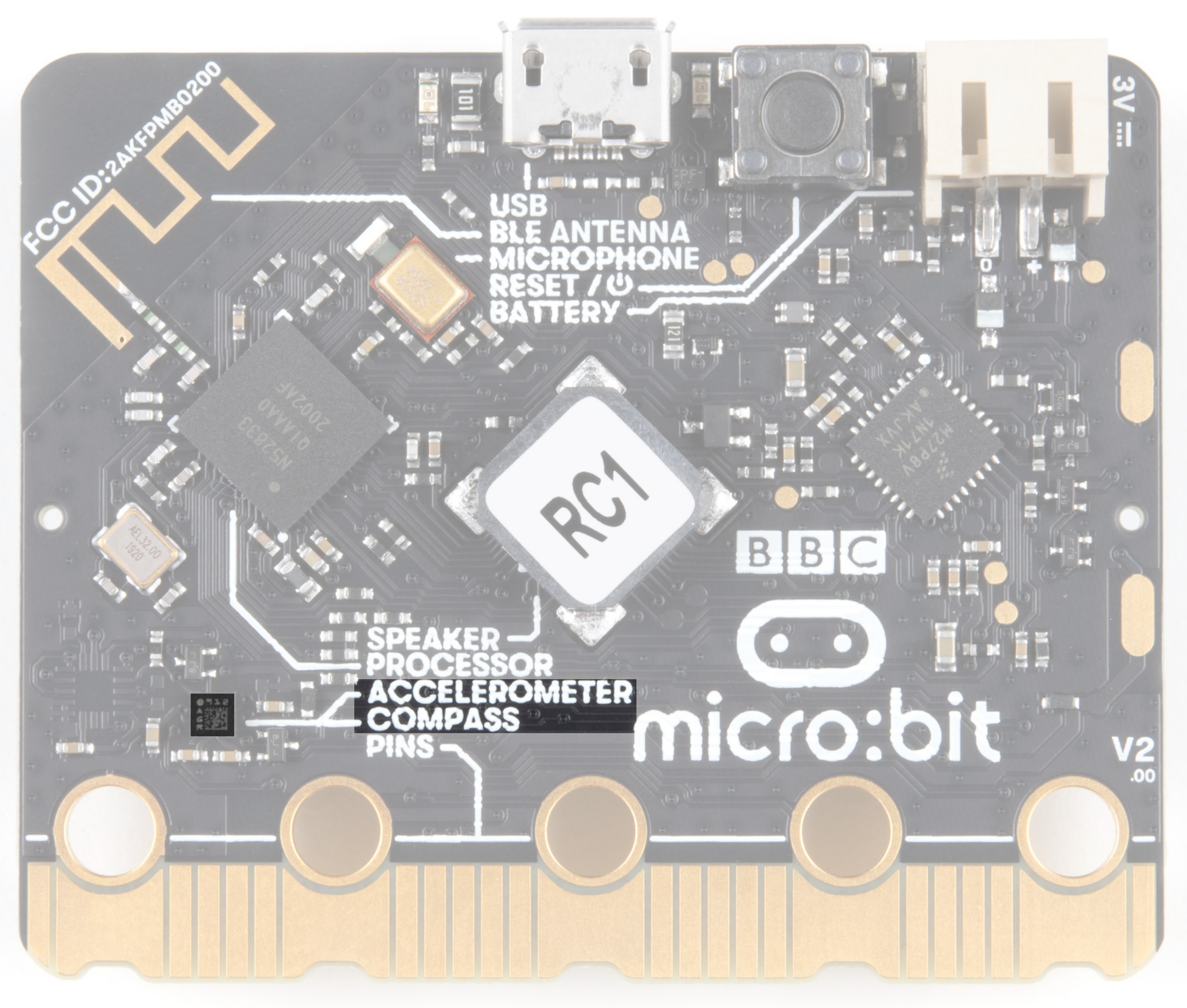 |
| Accelerometer and Magnetometer on micro:bit | Accelerometer and Magnetometer on micro:bit v2 |
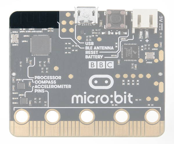
Bluetooth/Radio
Communication is huge with the micro:bit. You can communicate with your phone or tablet using Bluetooth Low Energy (BLE) or between two or more micro:bits using the standard 2.4GHz "radio". Note that the micro:bit v1 uses BLE Bluetooth v4.0 while micro:bit v2 uses BLE Bluetooth v5.0.
 |
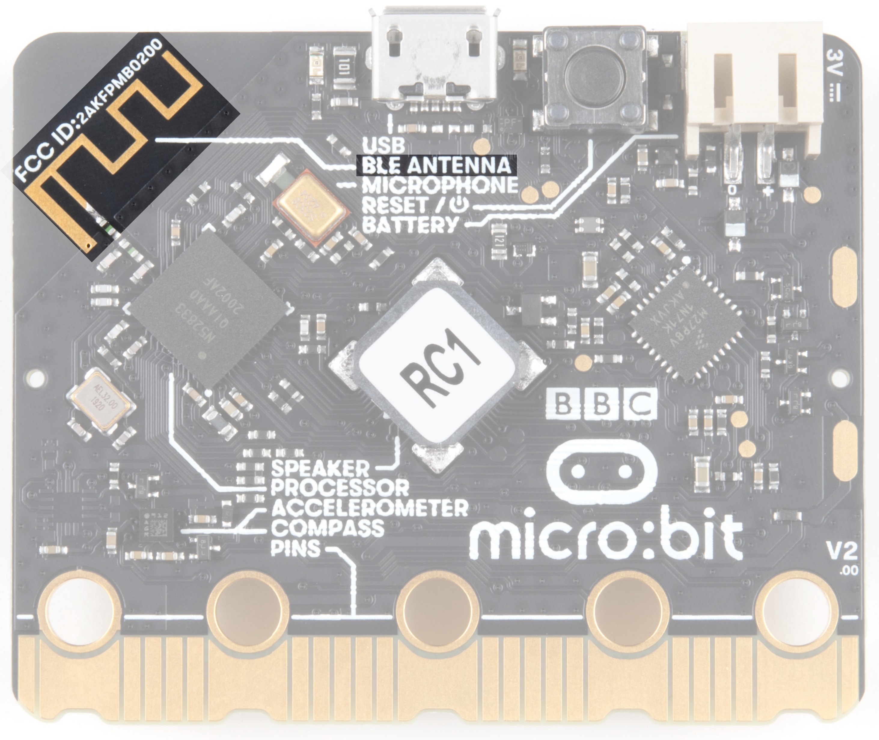 |
| Bluetooth / Radio Antenna on micro:bit | Bluetooth / Radio Antenna on micro:bit v2 |
Temperature Sensor
No, the drawing is not highlighted incorrectly! The microcontroller doubles as a temperature sensor!
|
|
| Microcontroller as Temperature Sensor on micro:bit | Microcontroller as Temperature Sensor on micro:bit v2 |
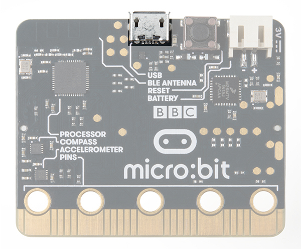
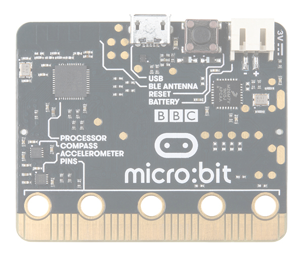
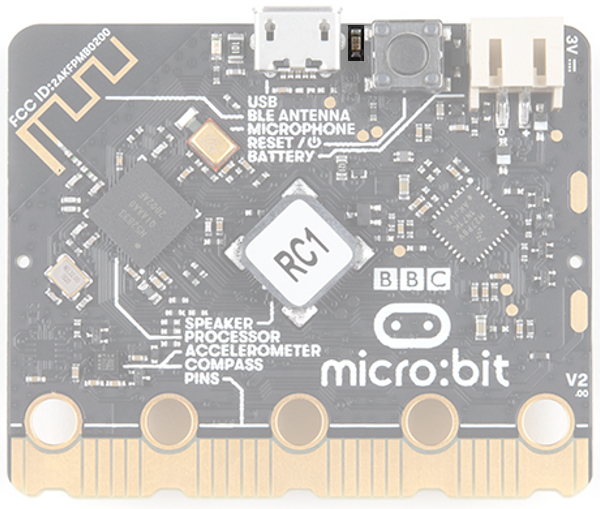
USB Port
Used to upload code to your micro:bit or power from your computer or laptop. You can also send and receive serial data from the MakeCode Serial Console or a Serial Terminal.
 |
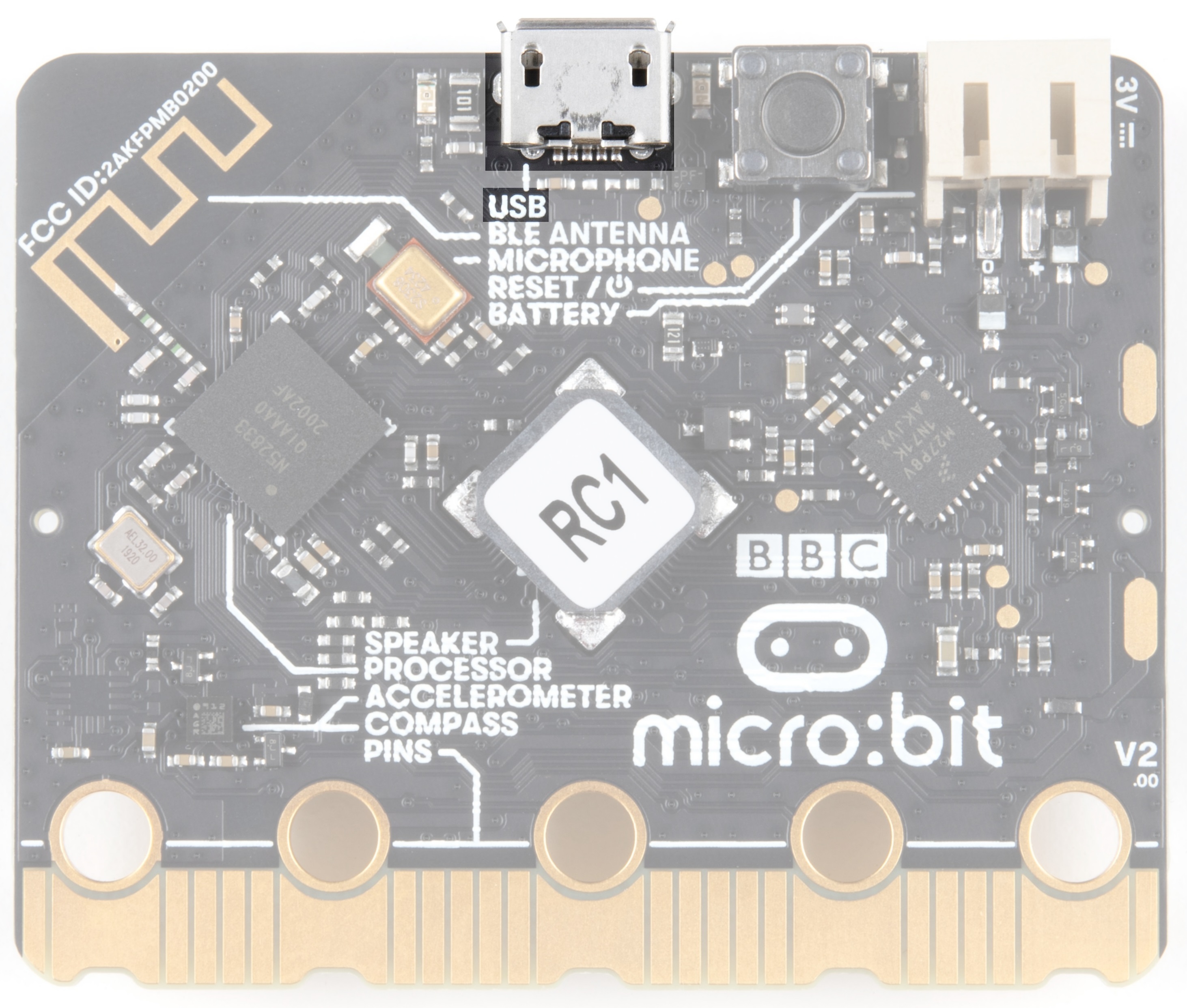 |
| USB Port on micro:bit | USB Port on micro:bit v2 |
USB Activity LED Indicator
When there is activity on the USB pins, the LED on the right will light up.
 |
 |
| USB Activity LED Indicator on micro:bit | USB Activity LED Indicator on micro:bit v2 |
V2 Only - Power LED
V2 of the micro:bit also includes a power LED next to the USB connector to indicate power is available.
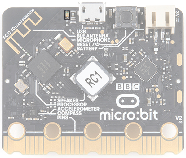
Reset Button
A button to reset your micro:bit and start your code over from the beginning.
 |
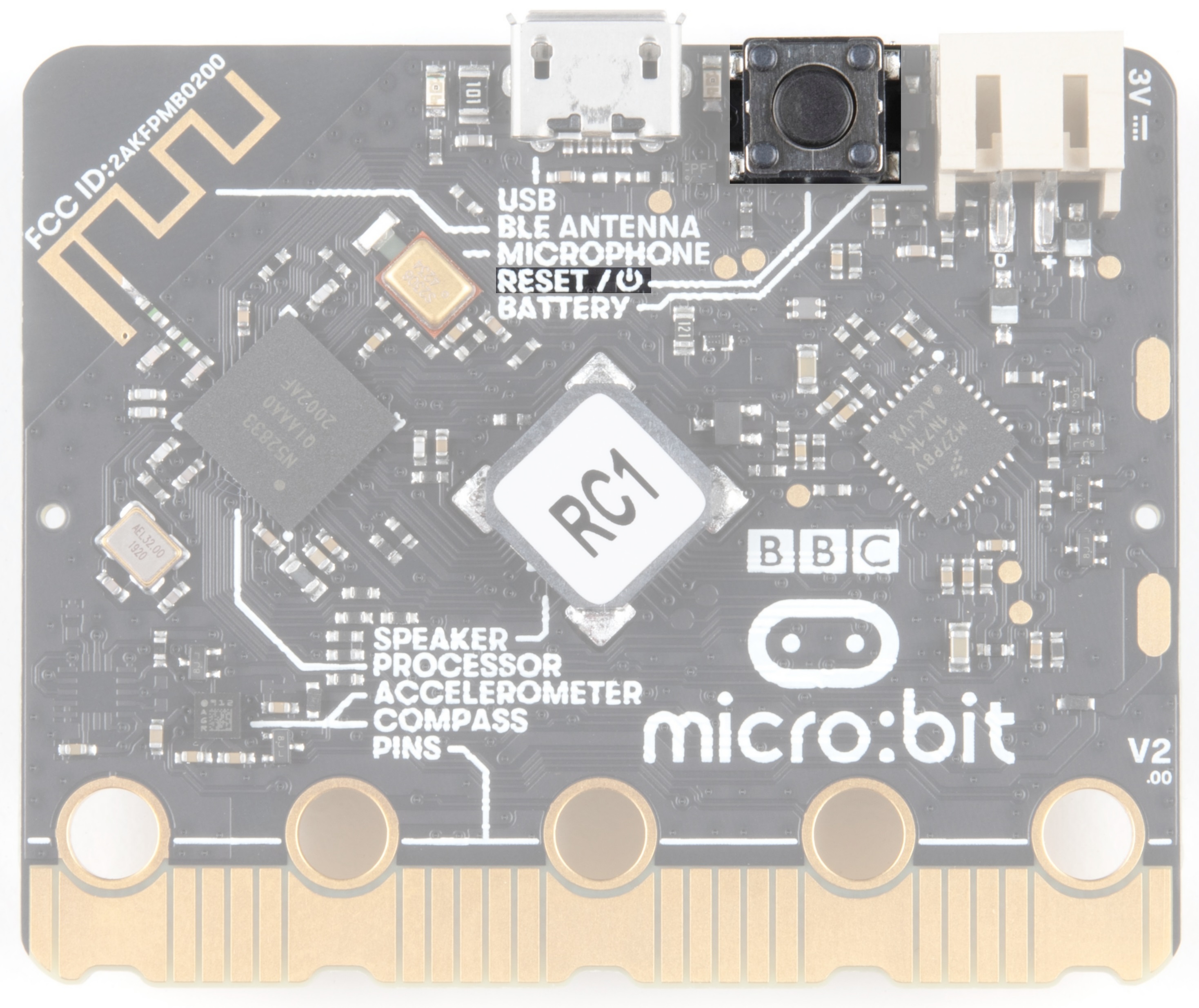 |
| Reset Button on micro:bit | Reset/ Power Button on micro:bit v2 |
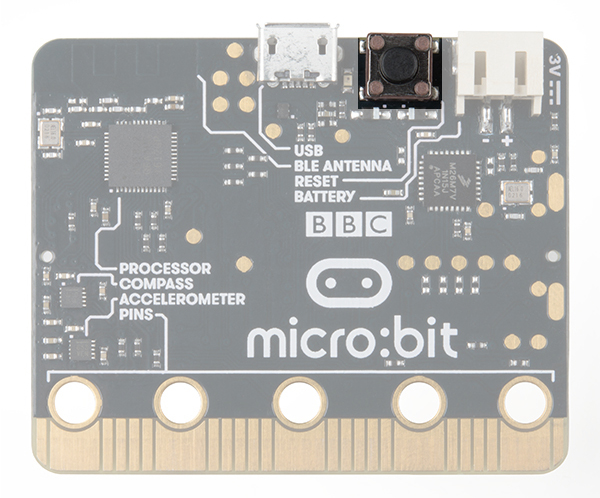
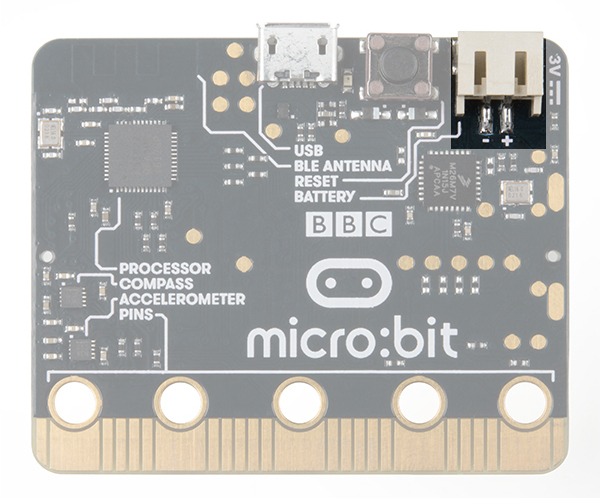
JST Battery Connector
A connector to hook up an external battery pack to your micro:bit.
 |
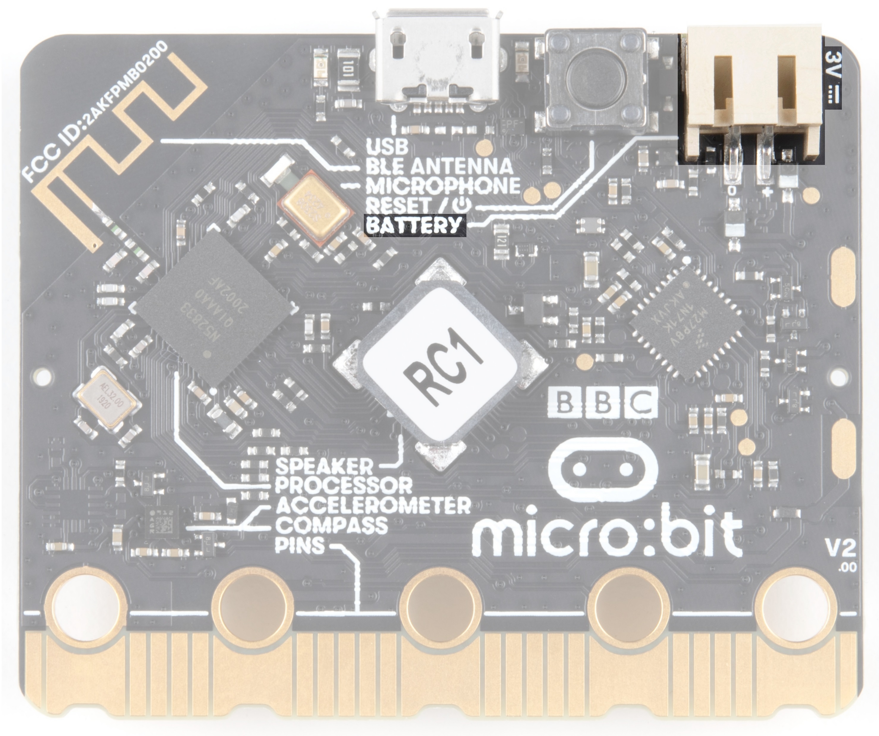 |
| JST Connector on micro:bit | JST Connector on micro:bit v2 |
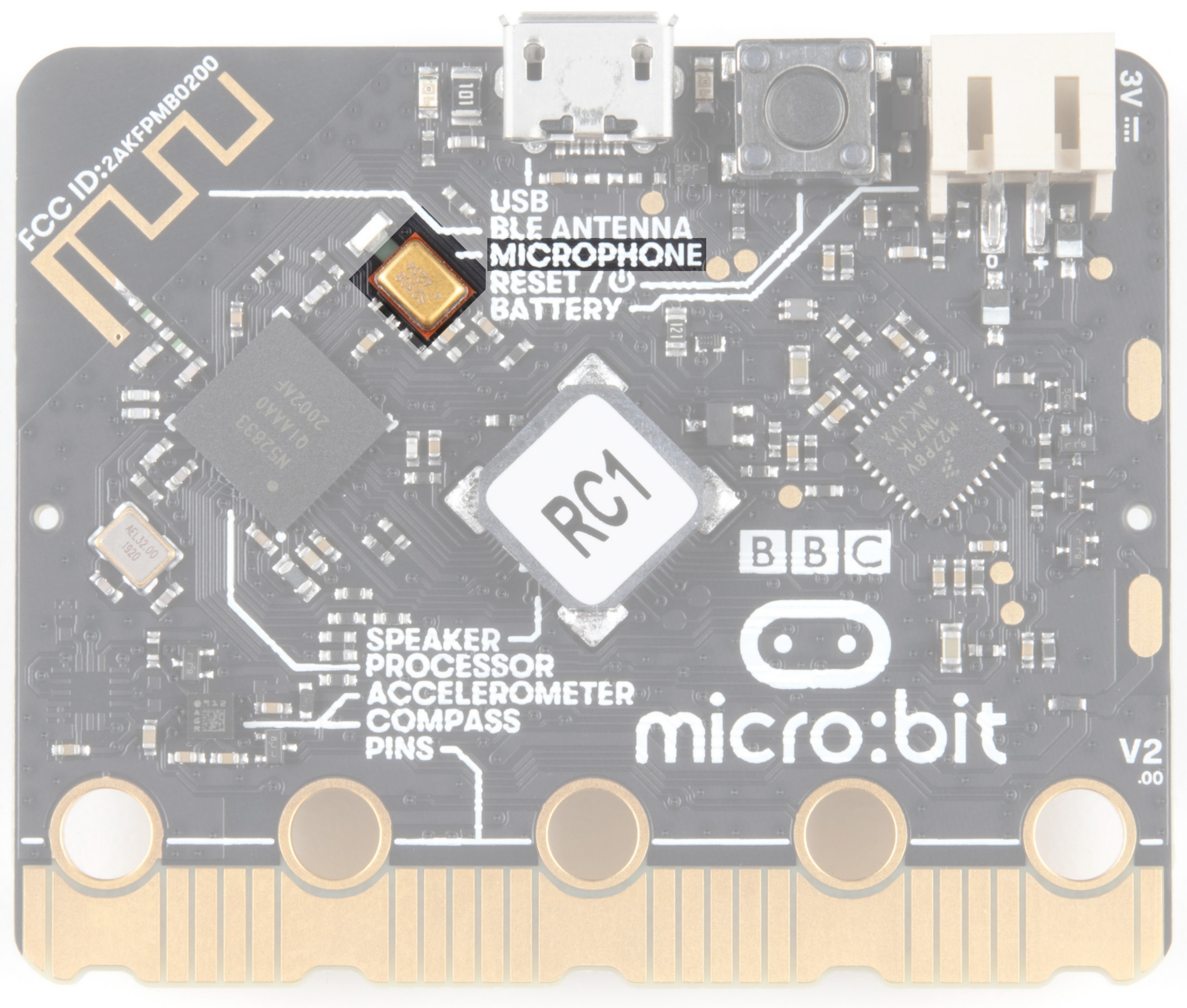
V2 Only - Microphone
V2 of the micro:bit contains a MEMS microphone to allow sound-sensing without the need to attach another device. If you look back at the front of the board, you will notice that the microphone input leads to this component on the back.
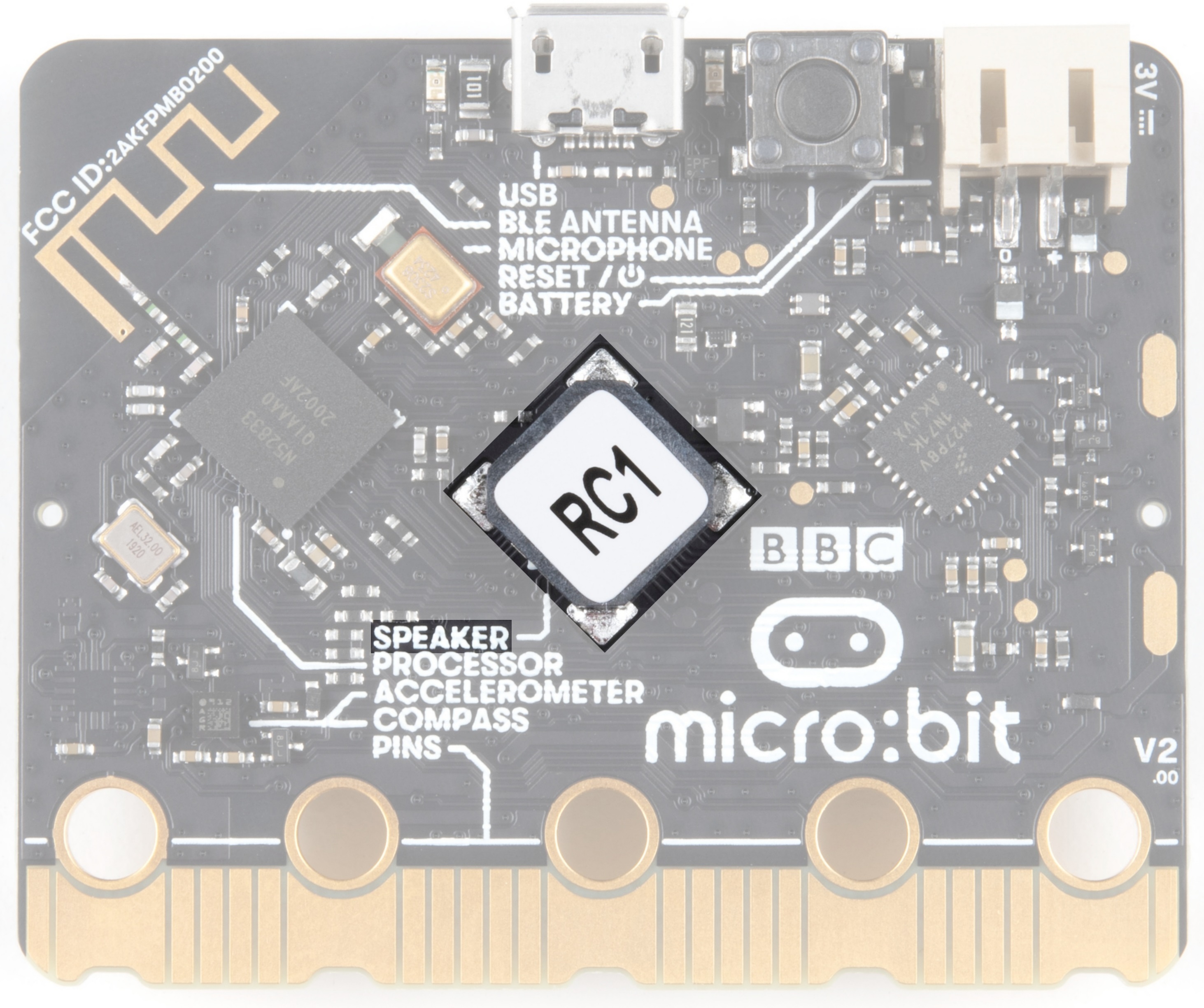
V2 Only - Speaker
V2 of the micro:bit also includes a built-in speaker on the back of the board. For users using an external speaker on the edge pins, you will need to configure the built-in speaker in the programming language of your choice.
Phew! That is a lot of bells and whistles...a true Swiss army knife!
Hooking It Up
The micro:bit uses a microUSB cable to hook up to your computer or Chromebook. It is as simple as plugging the cable into your micro:bit and the other end into an open USB port.
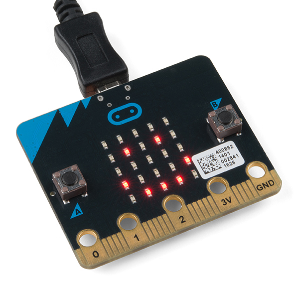
Once you plug your board in, you should see the small yellow LED on the back of your micro:bit light up and possibly blink a few times. Then whatever existing program that was put on the micro:bit will start running. If this is your first time plugging your micro:bit in, go ahead and play around with it a bit --- push buttons, shake it, and you will get a bit of an Easter egg.
Once your micro:bit boots up, check out your Finder if you are on a Mac, or your My Computer Drives if you are on a PC. The micro:bit should show up as an external storage device with two files stored in it.
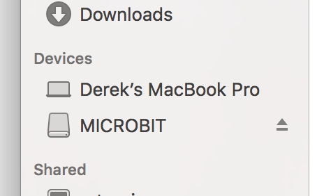
If you are on a Chromebook, when you plug your micro:bit in you will be greeted with a dialog box to open the drive. Feel free to do so to make sure it works!
Introduction to Microsoft MakeCode
What is MakeCode?
MakeCode is an open programming environment built by Microsoft for the micro:bit, as well as other boards. You can navigate to MakeCode for the micro:bit by clicking on the button below.
Once you have launched MakeCode, you will be greeted by its basic layout with a simulator on the left and a block-based environment on the right, as shown here.
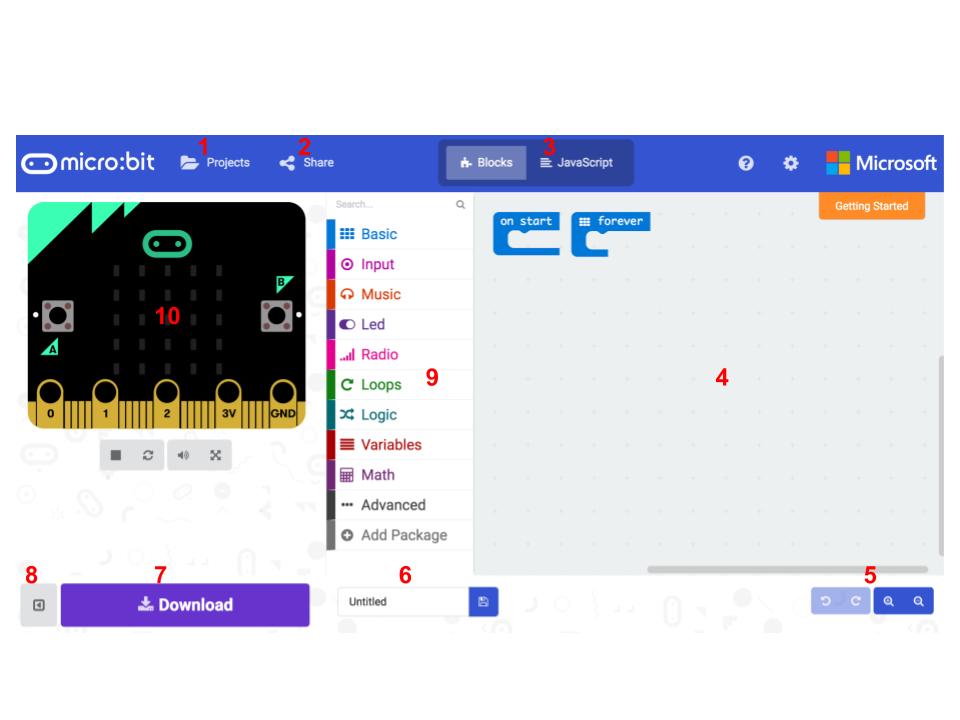
Let's take a quick tour and check out what is available to us!
- Projects --- A cloud storage system connected to your computer with no account setup required.
- Share --- Allows you to share your project code in a number of different ways with your friends!
- Blocks/JavaScript/Python --- Choose your own adventure by programming in blocks (default) or in JavaScript. Not shown in the image, Microsoft also eventually added an additional option to use convert the code to MicroPython.
- Program Space --- This is where the magic happens and where you build your program...where you "make code."
- Zoom/Undo-Redo --- Sometimes you need to undo things, or zoom out and look around; these are the buttons for that.
- Name & Save --- Name your program and save it (download it) to your computer.
- Download --- Similar to Save, download your program as a .hex file and drag it into your micro:bit.
- Block Library --- All of the options in terms of program building blocks, which are color-coded by function.
- Simulator Hide/Show --- You can hide/show the simulator if you would like.
- Simulator --- You don't need hardware! MakeCode has a real-time simulator! As you change your program, you can see what it will do on this virtual micro:bit!
Phew! Now you have a choice: block- or text-based programming?
Blocks or Text
For this guide and the majority of the content that you will find on SparkFun for the micro:bit, we will be using block-based programming examples.
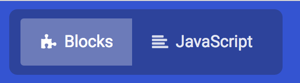
But, if you so choose, there is a JavaScript (and also MicroPython) option to use as well. The choice is yours, and the good news is that you can switch back and forth from one to the other in the same program; one will populate the other, which is really nice if you are new to programming!
Simulator
MakeCode includes a simulator for the micro:bit, meaning if you don't have your micro:bit in hand you can still write code for it. Or if you want to try out an idea before you upload it to your micro:bit, you can do that too!
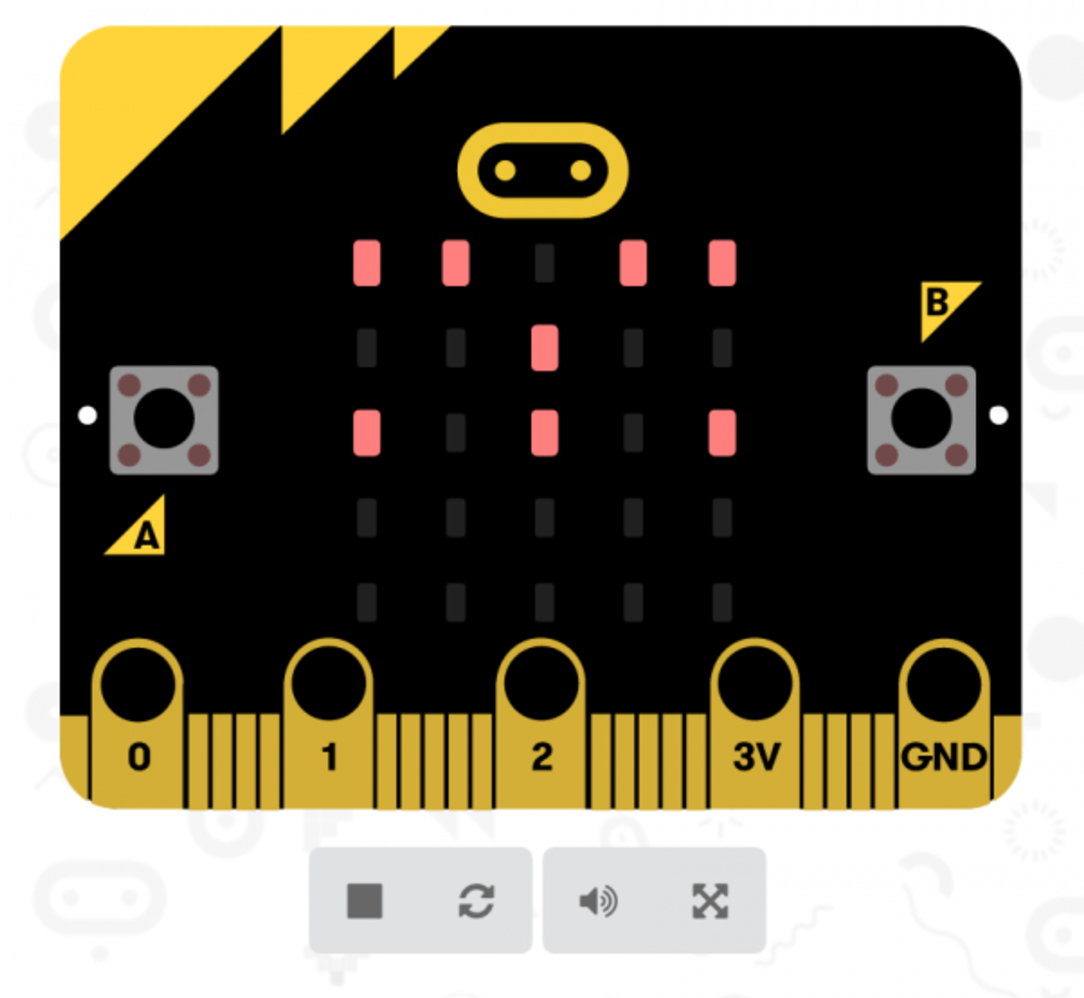
The simulator will update as you build your code, and if you want to run it from the beginning you can click the stop and run buttons to start it over again!
Speaking of code, let's write a quick program and get it onto your micro:bit!
Experiment 0: Hello, micro:bit!
Introduction
"Hello World" is the term we use to define that first program you write in a programming language or on a new piece of hardware. Essentially it is a simple piece of code that gives you a quick win (fingers crossed) and a first step in learning. It also gives you a chance to make sure everything is up and running and A-OK.
Parts Needed
You will need the following parts:
- 1x micro:bit
- 1x Micro B USB Cable

Running Your Script
For your first "Hello World" we are going to create a simple animation on the LED array that repeats forever. If you just want the complete program, you can see it here. To see a step-by-step explanation of how we built the program, continue reading!
Either copy and paste, or re-create the following code into your own MakeCode editor by clicking the open icon in the upper right-hand corner of the editor. You can also just download this example by clicking the download button in the lower right-hand corner of the code window.
Building 'Hello World'
A "Hello World" on the micro:bit is a little different than on a normal run-of-the-mill microcontroller. The micro:bit has no single LED to blink on its own, as you would find on the Arduino or similar boards. What the micro:bit does have is an LED array! So, the "Hello World" for the micro:bit is to draw something using the LED array!
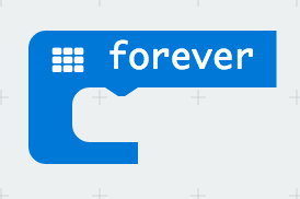
When you open MakeCode you are greeted with two blocks: the On Start block and the forever block. The On Start block is all of your code that will execute at the very beginning of your program and only run once. The forever block is code that will loop over and over again...forever.
We are going to use the forever block for building this "Hello World." We now need to start adding blocks to forever.
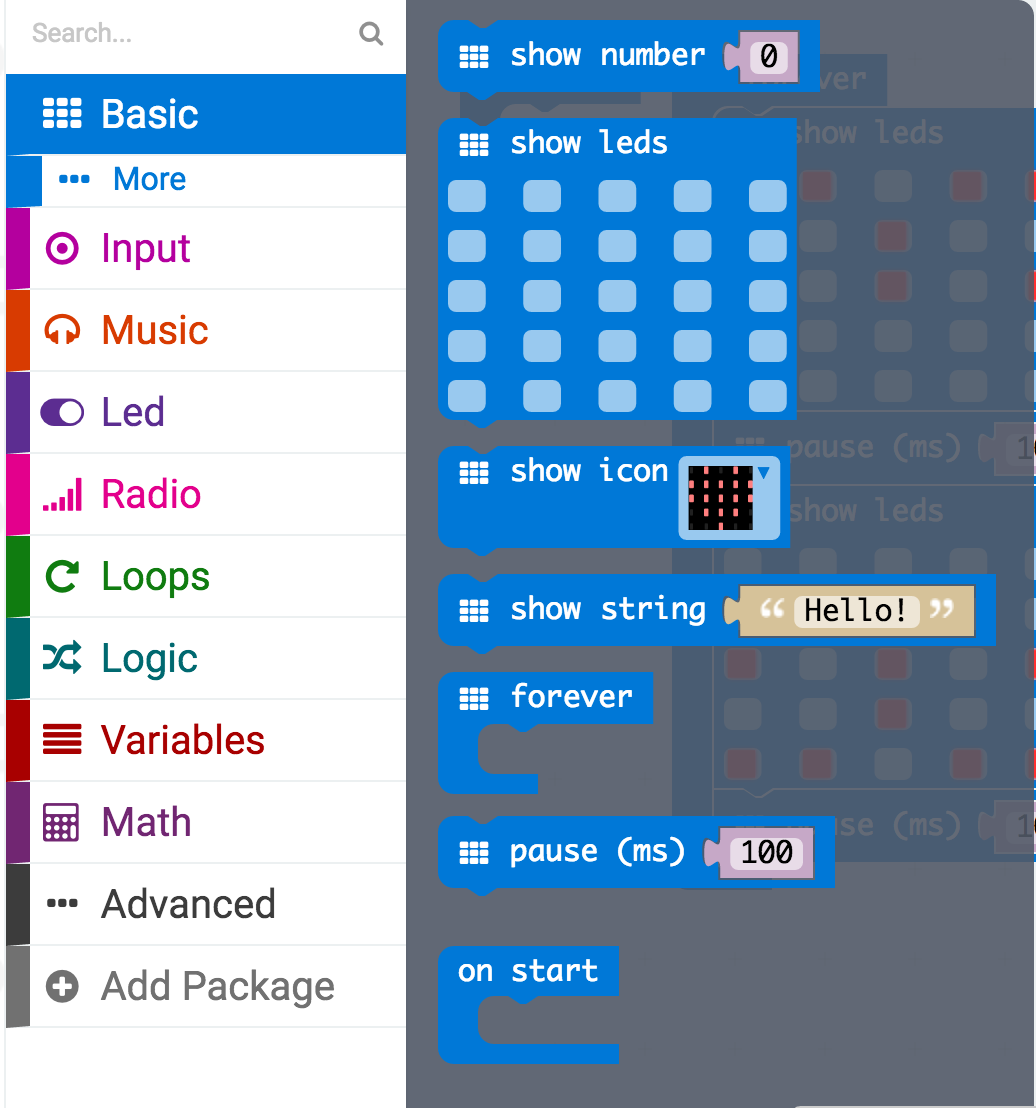
First, click on the Basics category. These blocks are, well, the basic building blocks of a BuildCode program. It will expand into a number of options. Click and drag the show leds block over and place it inside of your forever block. Notice that the block is keyed to fit inside of the forever block, and if you have the volume up on your computer you will hear a satisfying 'click' noise when you let go of the block.
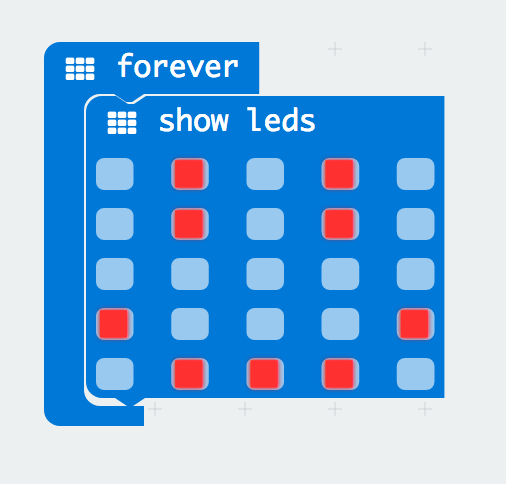
The show leds block has an array of squares that symbolize the LED array. If you click on a square, it will turn red, which means that it is on. Draw a simple pixel art shape by turning different LEDs on or off; you should be able to see the outcome in your simulator on the lefthand side of your window.
To turn this static image into an animation, we need another show leds block to place just under the first block. You can then make a second drawing with this set of rectangles. In your simulator you will see the images switching really, really fast. We need to slow this down!
To slow your animation down, you will use the pause block, which is under the basic block set. The pause block is just what it says; it tells the micro:bit to pause and wait for a certain amount of time. Place two pause blocks in the program as shown.
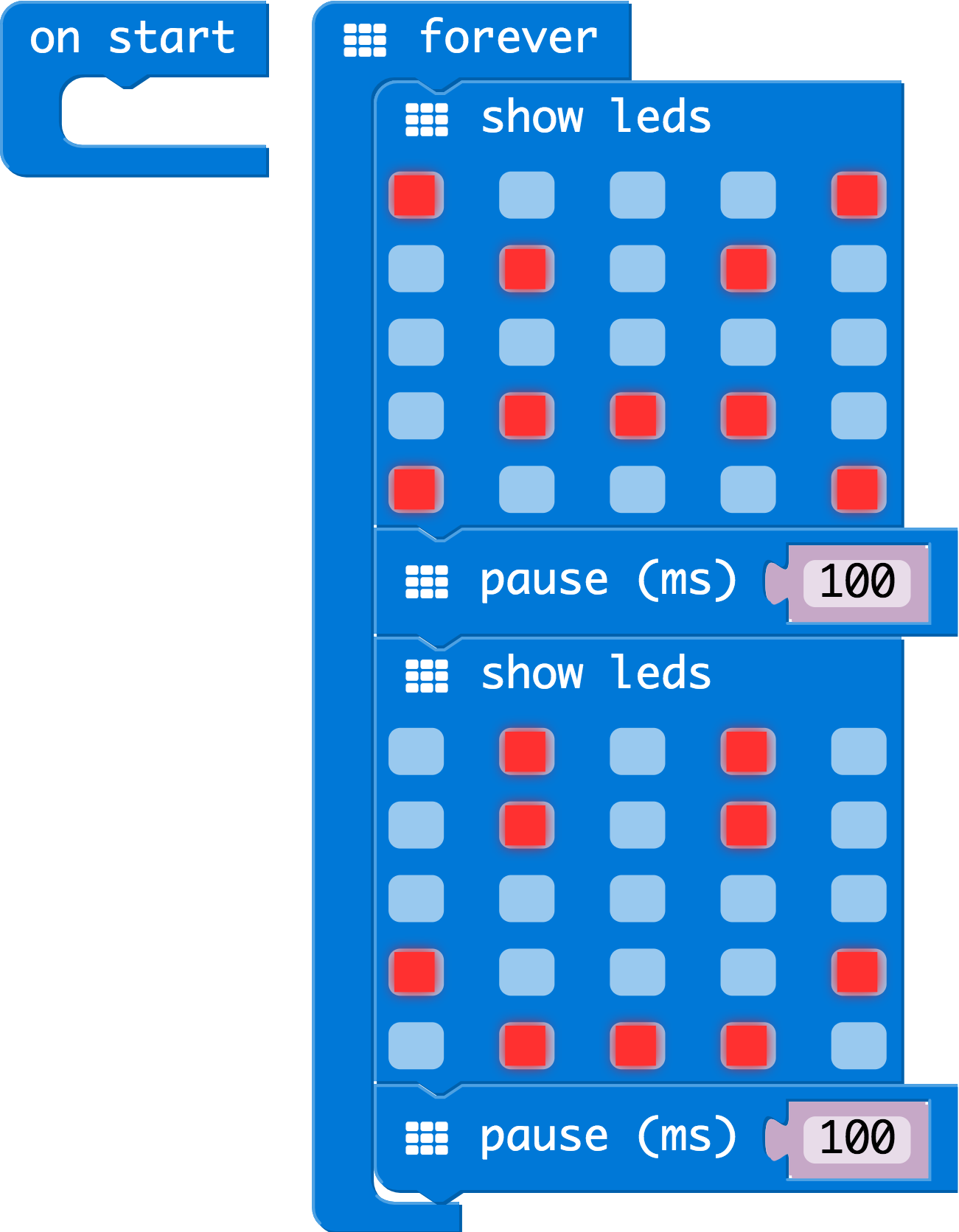
The reason we are using two and placing one at the end is that this program is a loop. Without the block at the end, the image in your animation will change really, really fast.
We have built up an example in the next section where you can download the file and try it out on your own micro:bit, or use the simulator. If you want to play around with the code and make some changes, go ahead and click the Edit button in the widget, and it will open a MakeCode editor for you to start hacking "Hello World." Enjoy!
Download Your Program
Either copy and paste, or recreate the following code in your own MakeCode editor. You can also just download this example by clicking the download button in the upper righthand corner of the code window.

This will download your program file to your standard download location, probably the Downloads folder on your computer, or whatever location you have set in your download preference.
You then simply click and drag your program file from its download location to your micro:bit drive, which shows up as an external device.
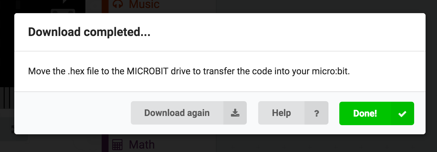
If you have not already, insert the USB cable into the micro:bit. Once it shows up as a drive, drag and drop the file into the micro:bit. That's it!
Your micro:bit will flash for a few seconds, and then your program will start automatically. Yes! Win!
Experiment 1: Blinking an LED
Introduction
LEDs are small, powerful lights that are used in many different applications. To start off, we will work on blinking an LED, the basic introduction of microcontrollers and building circuits. You already did a "Hello World" for the micro:bit itself, this is the next step. That's right --- it's as simple as turning a light on and off. It might not seem like much, but establishing this important baseline will give you a solid foundation as we work toward more complex experiments.
Parts Needed
You will need the following parts:
- 1x micro:bit
- 1x Micro B USB Cable
- 1x micro:bit Breakout (with Headers)
- 1x Breadboard
- 1x Jumper Wire
- 1x LED
- 1x 100Ω Resistor
Didn't Get the SIK for micro:bit?
If you are conducting this experiment and didn't get the Inventor's Kit, we suggest using these parts:


Suggested Reading
Before continuing with this experiment, we recommend you be familiar with the concepts in the following tutorial:
- Light-Emitting Diodes --- Learn more about LEDs!
- How to Use a Breadboard --- Learn the basics of using a breadboard!
How to Use a Breadboard
Light-Emitting Diodes (LEDs)
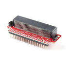
Introducing the micro:bit Breakout
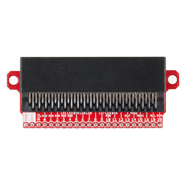
To extend the functionality of the micro:bit beyond what is already on the board, we developed a micro:bit breakout. For users with earlier versions of the SparkFun Inventor's Kit for micro:bit, users will be using the micro:bit Breakout Board as shown below on the left. Eventually the board had a revision as shown on below on the right. Don't worry, the overall functionality is the same. The difference is that the board includes a Qwiic enabled connector and surface mount edge connector. Throughout the tutorial, we will be using the micro:bit breakout board in the images and hookup diagrams.
 |
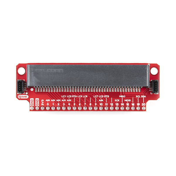 |
| micro:bit Breakout Board (with Headers) | Qwiic micro:bit Breakout Board (with Headers) |
This breakout board makes it much easier to use all of the pins available on the micro:bit edge connector in a more user-friendly way. We also broke out ground and VCC (3.3 volts) for your convenience.
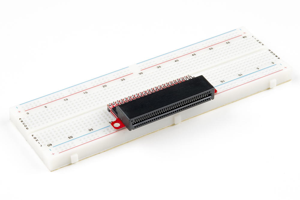
The breakout board lines up with the pins of a breadboard. We recommend using a full-sized breadboard with this breakout to give you enough room to prototype circuits on either end of the breadboard. Also, for durability's sake, insert the breakout pins about halfway into the breadboard so there is support under the board for when you insert a micro:bit and/or pull it out.
Introducing the LED
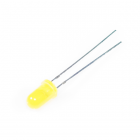
A Light-Emitting Diode (LED) will only let current through in one direction. Think of an LED as a one-way street. When current flows through the LED, it lights up!
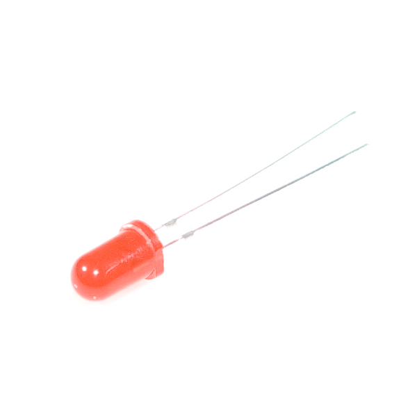
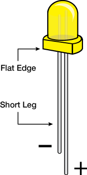
When you are looking at the LED, you will notice that its legs are different lengths. The long leg, the "anode," is where current enters the LED. This pin should always be connected to the current source. The shorter leg, the "cathode," is the current’s exit. The short leg should always be connected to a pathway to ground.
LEDs are finicky when it comes to how much current you apply to them. Too much current can lead to a burnt-out LED. To restrict the amount of current that passes through the LED, we use a resistor in line with the power source and the LED's long leg; this is called a current-limiting resistor. With the micro:bit, you should use a 100Ω resistor. We have included a baggy of them in the kit just for this reason!
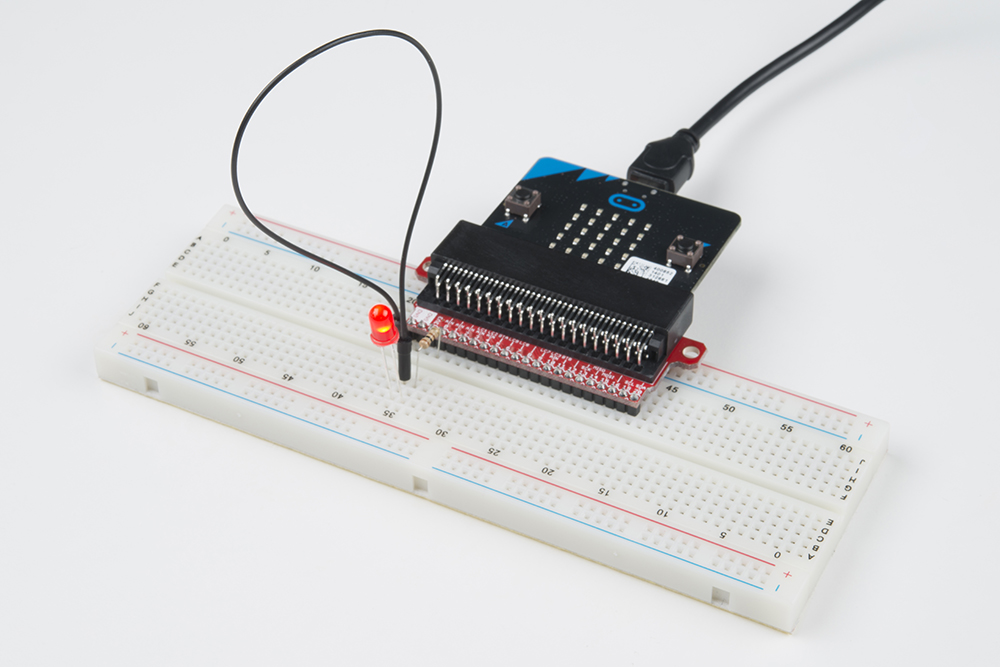
Hardware Hookup
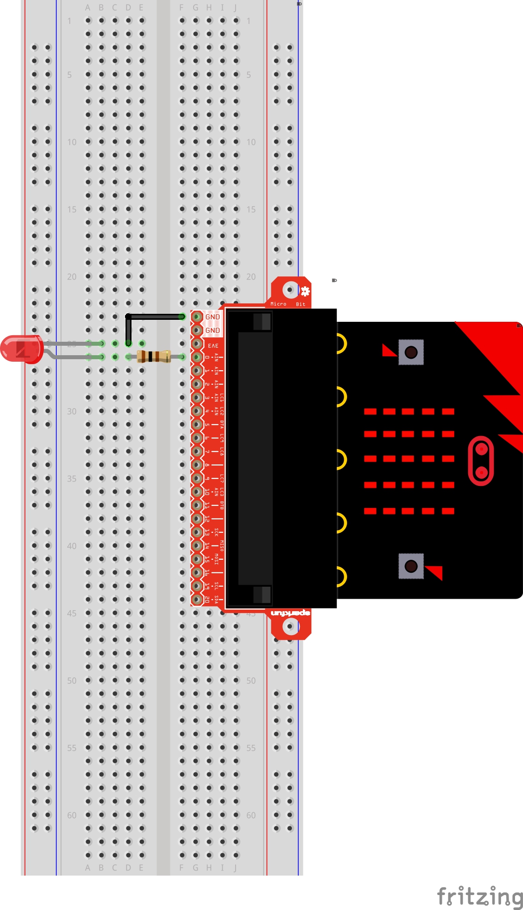
Ready to start hooking everything up? Check out the wiring diagram and hookup table below to see how everything is connected.
| Polarized Components | Pay special attention to the component’s markings indicating how to place it on the breadboard. Polarized components can only be connected to a circuit in one direction. |
Please note: Pay close attention to the LED. The negative side of the LED is the short leg, marked with a flat edge.
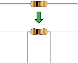
Components like resistors need to have their legs bent into 90° angles in order to correctly fit the breadboard sockets. You can also cut the legs shorter to make them easier to work with on the breadboard.
Wiring Diagram for the Experiment
Running Your Script
Either copy and paste, or re-create the following code into your own MakeCode editor by clicking the open icon in the upper right-hand corner of the editor. You can also just download this example by clicking the download button in the lower right-hand corner of the code window.
Code to Note
Let's take a look at the code blocks in this experiment.
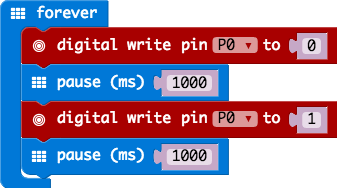
Forever
The forever block is a block that loops any other command blocks inserted into it over and over again...forever. It starts from the top and executes your code in order working its way to the bottom and then starts at the top again.
Digital Write
The DigitalWrite block enables you to turn a pin on or off. There is a dropdown option for which pin you want to control, and it accepts a variable as the pins state. You use 1 as on and 0 as off. If you prefer, you can also use Boolean states of true and false, but we will use 0 and 1 as our standard throughout this guide.
Pause
If you were to just turn pins on and off with the digital write block without a pause, the LED would blink really, really fast. The pause block enables you to slow the micro:bit down and lets you control the timing of things happening. It accepts a number or variable as the number of milliseconds you want the micro:bit to pause. Think of this block as a stoplight for your code!
Led > more > led enable false . For more information on the GPIO pins reserved for the LED array, check out the link below.
What You Should See
You should see your LED blink on and off at 1-second intervals. If it doesn't, make sure you have assembled the circuit correctly and verified and uploaded the code to your board, or see the Troubleshooting section.
Troubleshooting
LED Not Blinking
Make sure you have it wired correctly and the correct pin to ground. Remember, short pin to ground; long pin to signal.
Still No Success
A broken circuit is no fun. Send us an email, and we will get back to you as soon as we can: techsupport@sparkfun.com .
Experiment 2: Reading a Potentiometer
Introduction
In this circuit you will work with a potentiometer. You will learn how to use a potentiometer to control the brightness of an LED by reading a sensor and storing its 0--1023 value as a variable, then using it as a brightness level for the LED.
Parts Needed
You will need the following parts:
- 1x micro:bit
- 1x Micro B USB Cable
- 1x micro:bit Breakout (with Headers)
- 1x Breadboard
- 8x Jumper Wires
- 1x 10kΩ Potentiometer
- 1x LED
- 1x 100Ω Resistor
Didn't Get the SIK for micro:bit?
If you are conducting this experiment and didn't get the Inventor's Kit, we suggest using these parts:

Suggested Reading
Before continuing with this experiment, we recommend you be familiar with the concepts in the following tutorial:
Analog to Digital Conversion
Introducing the Potentiometer
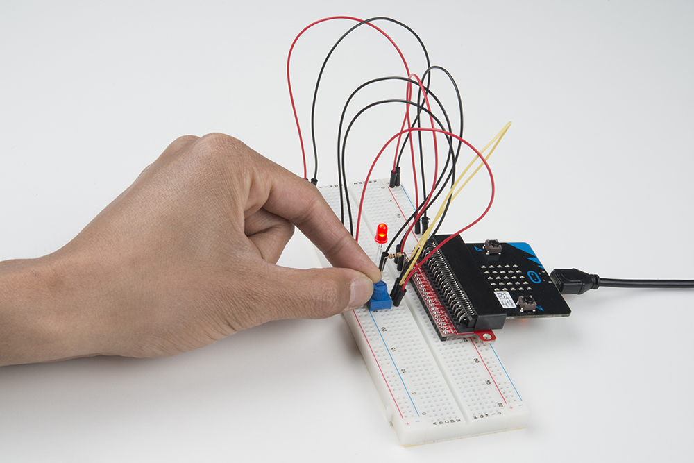
A potentiometer is a resistance-based analog sensor that changes its internal resistance based on the rotation of its knob. The potentiometer has an internal voltage divider enabling you to read the change in voltage on the center pin with a microcontroller (i.e. micro:bit).
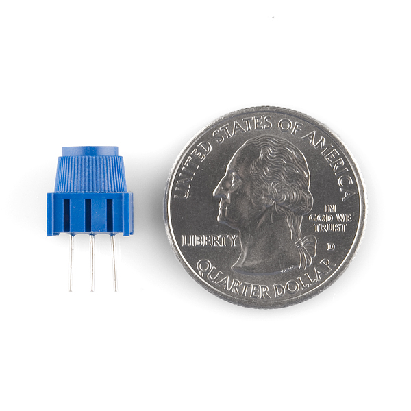
To hook up the potentiometer, attach the two outside pins to a supply voltage (3.3V in this circuit) and ground. It doesn’t matter which is connected where, as long as one is connected to power, and the other to ground. The center pin is then connected to an analog input pin so the micro:bit can measure the change in voltage. When you twist the knob, the sensor reading will change!
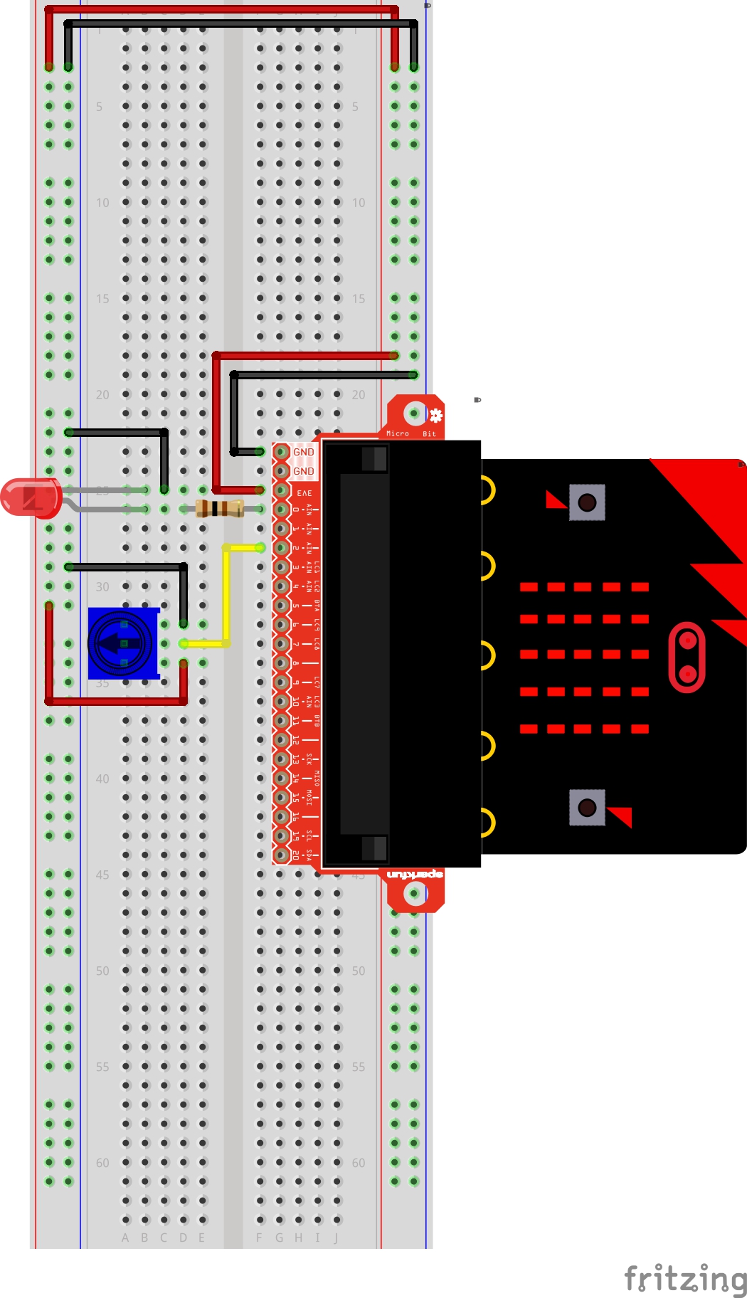
Hardware Hookup
Ready to start hooking everything up? Check out the wiring diagram and hookup table below to see how everything is connected.
| Polarized Components | Pay special attention to the component’s markings indicating how to place it on the breadboard. Polarized components can only be connected to a circuit in one direction. |
Wiring Diagram for the Experiment
Running Your Script
Either copy and paste, or re-create the following code into your own MakeCode editor by clicking the open icon in the upper right-hand corner of the editor. You can also just download this example by clicking the download button in the lower right-hand corner of the code window.
Code to Note
Let's take a look at the code blocks in this experiment.
A “variable” is a placeholder for values that may change in your code. You can create a variable using th Make Variable option underneath the Variables group. You can then name it, which then creates a block for your given variable.
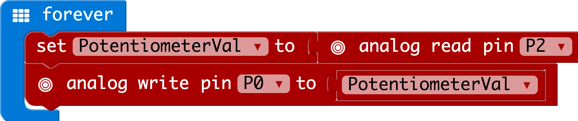
Set To
To store a value inside of your newly created variable you use the set to block. The set to block allows you to select from a list of the variables that exist in your program and then add a value that you want to store or set that variables to.
Analog Read
In this program you are reading the voltage from the potentiometer which is 0 to 3.3 volts. The micro:bit reads that value as a 10 bit number which is a value range from 0 to 1023 using the analog read block. The analog read block is a value based block, meaning that you have to insert it into a block with a matching shape. We insert it into the set to block to store its value as a variable.
Analog Write
Just like the analog read block the analog write block deals with a range of values, but instead of reading a pin as an input the analog write block outputs an analog value to a pin. We see this as a brightness range with this led, but it could be a tone from a buzzer, a motor speed, etc. We set our analog output to the variable we stored the potentiometer value in.
What You Should See
You should twist the potentiometer. You will notice that the LED will get brighter or dimmer based on the position of the potentiometer. If you turn the potentiometer all the way one direction it will be fully on and the other end will be fully off.
Troubleshooting
Sporadically Working
This is most likely due to a slightly dodgy connection with the potentiometer's pins. This can usually be conquered by holding the potentiometer down or moving the potentiometer circuit somewhere else on your breadboard.
Not Working
Make sure you haven’t accidentally connected the wiper (center pin), the resistive element in the potentiometer, to a wrong pin!
LED Not Lighting Up
LEDs will only work in one direction. Double check your connections.
Experiment 3: Reading a Photoresistor
Introduction
In Experiment 2, you got to use a potentiometer, which varies resistance based on the twisting of a knob and, in turn, changes the voltage being read by the analog input pin. In this circuit you’ll be using a photoresistor, which changes resistance based on how much light the sensor receives. You will read the light value of the room and have an LED turn on if it is dark and turn off if it is bright. That's right; you are going to build a night light!
Parts Needed
You will need the following parts:
- 1x micro:bit
- 1x Micro B USB Cable
- 1x micro:bit Breakout (with Headers)
- 1x Breadboard
- 8x Jumper Wires
- 1x Photoresistor
- 1x 10kΩ Resistor
- 1x LED
- 1x 100Ω Resistor
Didn't Get the SIK for micro:bit?
If you are conducting this experiment and didn't get the Inventor's Kit, we suggest using these parts:

Suggested Reading
Before continuing with this experiment, we recommend you be familiar with the concepts in the following tutorial:
Resistors
Voltage Dividers
Introducing the Photoresistor
The photoresistor changes its resistance based on the light to which it is exposed.
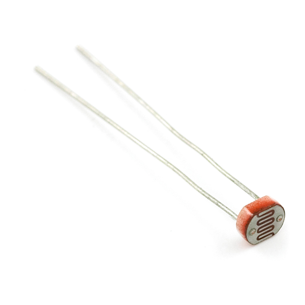
To use this with the micro:bit, you will need to build a voltage divider with a 10kΩ resistor, as shown in the wiring diagram for this experiment. The micro:bit cannot read a change in resistance, only a change in voltage. A voltage divider allows you to translate a change in resistance to a corresponding voltage value.
The voltage divider enables the use of resistance-based sensors like the photoresistor in a voltage-based system. As you explore different sensors, you will find more resistance-based sensors that only have two pins like the photoresistor. To use them with your micro:bit you will need to build a voltage divider like the one in this experiment. To learn more about resistors in general, check out our tutorial on resistors and also our tutorial on voltage dividers if you have not already.
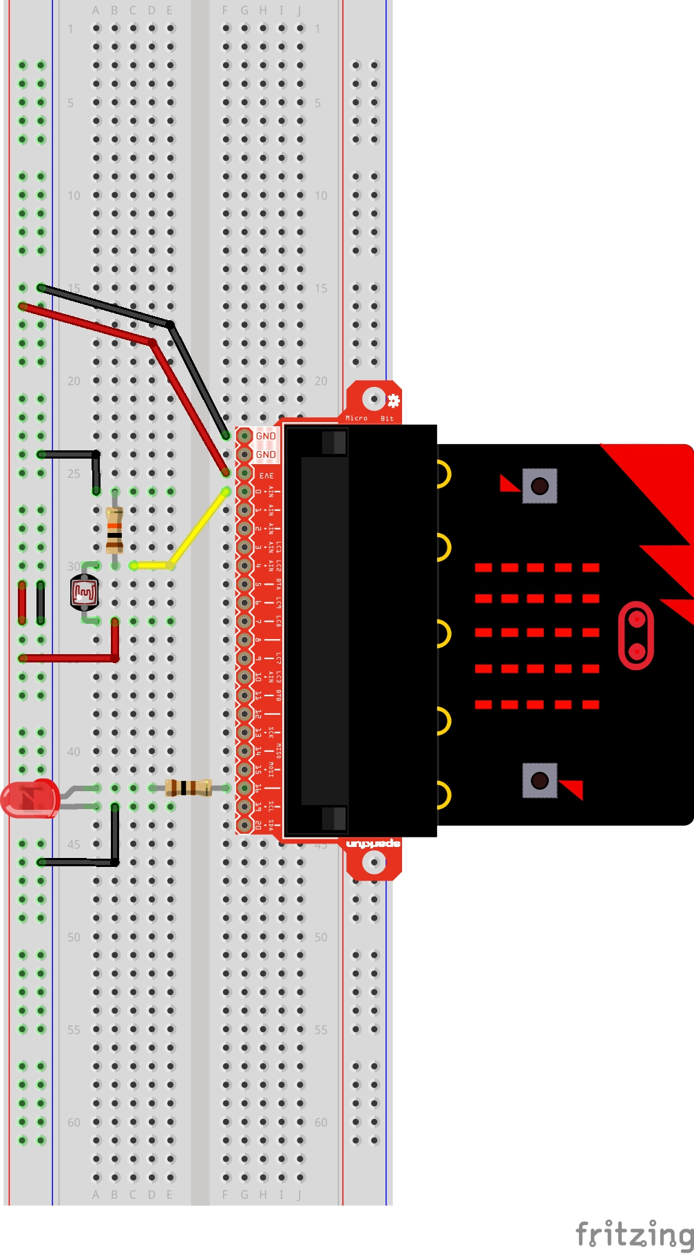
Hardware Hookup
Ready to start hooking everything up? Check out the wiring diagram below to see how everything is connected.
| Polarized Components | Pay special attention to the component’s markings indicating how to place it on the breadboard. Polarized components can only be connected to a circuit in one direction. |
Wiring Diagram for the Experiment
Running Your Script
Either copy and paste, or re-create the following code into your own MakeCode editor by clicking the open icon in the upper right-hand corner of the editor. You can also just download this example by clicking the download button in the lower right-hand corner of the code window.
Code to Note
Let's take a look at the code blocks in this experiment.
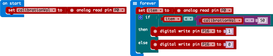
On Start
In previous experiments you have only used the forever block, which loops your code forever. The On start block is a block of code that only runs once at the very beginning of your program. In this program we use it to set a calibration value once, and then compare the changing value in the forever loop. This is a great spot for code that you only want to run a single time.
calibrationVal is a calibration variable. Your micro:bit takes a single reading of the light sensor in the on start block of code and uses this value to compare against the calibrationVal variable in the forever loop. This value doesn't change in the forever block, as it is set in the on start block. To update this value you can press the RESET button on the back of your micro:bit or power cycle the board.
If/Else
If the light value variable that is constantly being updated in the forever block is less than the calibration value minus 50, it is dark and the LED should turn on. The (-50) portion of the if block is a sensitivity value. The higher the value, the less sensitive the circuit will be; the lower the value, the more sensitive it will be to lighting conditions.
The if block is a logical structure. If the logical statement that is attached to it (item < calibrationVal -50) is true, then it will execute the code blocks inside of the if. If that statement is false, it will execute the else blocks. In this case if the statement is true (the room is dark), then the micro:bit will turn on the LED on pin 16; else (if the room is bright), it will turn the LED off using a digital write block.
What You Should See
When the micro:bit runs the program it will take a single reading from the light sensor and use that as a calibration value of the "normal" state of the room. When you place your hand over the light sensor or turn the lights off, the LED will turn on. If you turn the lights back on or uncover the light sensor, the LED will turn off.

Troubleshooting
LED Remains Dark
You may have been leaning over the light sensor when the code started. Make sure the light sensor is reading the normal light in the room at startup. Try resetting the micro:bit.
Still Not Quite Working
Double-check your wiring of the signal pin; sometimes you miss a breadboard connection by a row.
Experiment 4: Driving an RGB LED
Introduction
You know what’s even more fun than a blinking LED? Changing colors with one LED. In this circuit, you’ll learn how to use an RGB LED to create unique color combinations. Depending on how bright each diode is, nearly any color is possible!
Parts Needed
You will need the following parts:
- 1x micro:bit
- 1x Micro B USB Cable
- 1x micro:bit Breakout (with Headers)
- 1x Breadboard
- 1x Jumper Wire
- 1x Common Cathode RGB LED
- 3x 100Ω Resistors
Didn't Get the SIK for micro:bit?
If you are conducting this experiment and didn't get the Inventor's Kit, we suggest using these parts:
Suggested Reading
Before continuing with this experiment, we recommend you be familiar with the concepts in the following tutorial:
Pulse Width Modulation
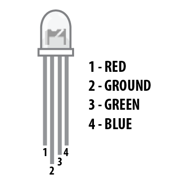
Introducing the Red/Green/Blue (RGB) LED
The Red/Green/Blue (RGB) LED is three LEDs in one. The RGB has four pins with each of the three shorter pins controlling an individual color: red, green or blue. The longer pin of the RGB is the common ground pin. You can create a custom-colored LED by turning different colors on and off to combine them. For example, if you turn on the red pin and green pin, the RGB will light up as yellow.

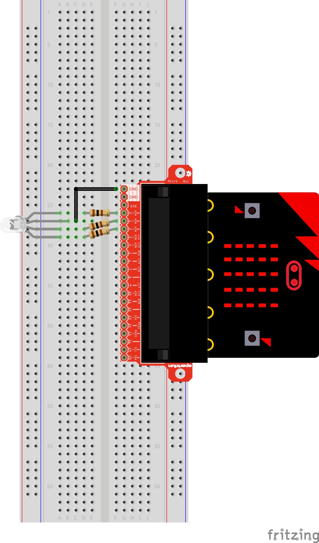
But which pin is which color? Pick up the RGB so that the longest pin (common ground) is aligned to the left as shown in the graphic below. The pins are Red, Ground, Green and Blue --- starting from the far left.
Hardware Hookup
Ready to start hooking everything up? Check out the wiring diagram and hookup table below to see how everything is connected.
| Polarized Components | Pay special attention to the component’s markings indicating how to place it on the breadboard. Polarized components can only be connected to a circuit in one direction. |
Wiring Diagram for the Experiment
Run Your Script
Either copy and paste, or re-create the following code into your own MakeCode editor by clicking the open icon in the upper right-hand corner of the editor. You can also just download this example by clicking the download button in the lower right-hand corner of the code window.
Code to Note
Let's take a look at the code blocks in this experiment.
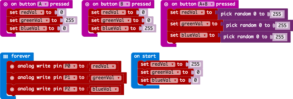
On Button Press
You will find the on Button Press block under the input block section. It is a different type of block than you are used to. It is what is called an event block --- code that is triggered when something happens, and only when that happens. In this case it is when one of the onboard buttons is pressed.
You can select between button A, button B and when both buttons (A+B) are pressed. Note that there is also a pin event function that works the same way, and you can use it with external buttons to build your own external hardware events.
Pick Random
In the on Buttons A+B pressed block you will notice that we set the color pin variables to random numbers using the pick random block. You give this block a range of values between 0 and another value. In this case we use 255, which is peak of the analog write block's output.
What You Should See
You should see your LED turn on red. If you press the A button on the micro:bit, the color will change to green; if you press the B button, the color will change to blue; and finally, if you press the A and B button, the RGB will turn a random color.

Troubleshooting
LED Remains Dark or Shows Incorrect Color
With the four pins of the LED so close together, it’s sometimes easy to misplace one. Double check that each pin is where it should be.
Seeing Red
The red diode within the RGB LED may be a bit brighter than the other two. To make your colors more balanced, use a higher ohm resistor.
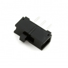
Experiment 5: Reading an SPDT Switch
Introduction
In this experiment you will use your first digital input: a switch. The SPDT (Single-Pole, Double-Throw) switch is a simple way to select between two options, especially when paired with an if state. You will use that switch to select which of the two LEDs will blink.
Parts Needed
You will need the following parts:
- 1x micro:bit
- 1x Micro B USB Cable
- 1x micro:bit Breakout (with Headers)
- 1x Breadboard
- 8x Jumper Wires
- 1x SPDT Switch
- 2x LED (1 Red, 1 Yellow)
- 2x 100Ω Resistors
Didn't Get the SIK for micro:bit?
If you are conducting this experiment and didn't get the Inventor's Kit, we suggest using these parts:
Suggested Reading
Before continuing with this tutorial, we recommend you be somewhat familiar with the concepts in these tutorials:
Button and Switch Basics
Digital Logic
Introducing the Single-Pole, Double-Throw (SPDT) Switch
The Single-Pole, Double-Throw (SPDT) switch has a common pin in the middle and then two other pins. A connection will be made between the middle pin and one of the other pins depending on the position of the switch.

Reading a switch is similar to a button. You need to connect the common pin to a digital General Purpose Input/Output (GPIO) pin to the micro:bit board from a breadboard. The other pins can be connected to 3.3V and ground. It doesn’t matter which pin is which. When you move the switch, the common pin will either be HIGH (connected to 3.3V) or LOW (connected to ground).
Hardware Hookup
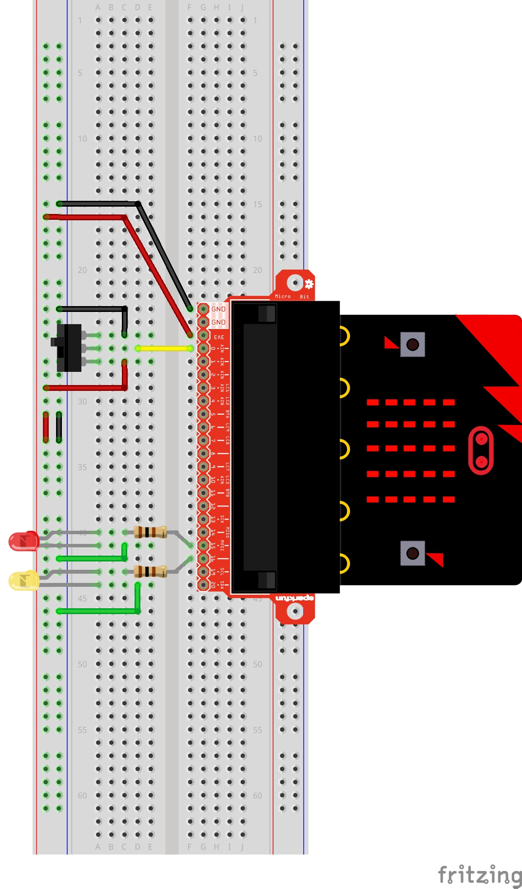
Ready to start hooking everything up? Check out the wiring diagram and hookup table below to see how everything is connected.
| Polarized Components | Pay special attention to the component’s markings indicating how to place it on the breadboard. Polarized components can only be connected to a circuit in one direction. |
Wiring Diagram for the Experiment
Run Your Script
Either copy and paste, or re-create the following code into your own MakeCode editor by clicking the open icon in the upper right-hand corner of the editor window. You can also just download this example by clicking the download button in the lower right-hand corner of the code window.
Code to Note
Let's take a look at the code blocks in this experiment.
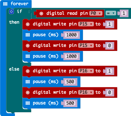
Digital Read
Just as the digital write block turns a pin on (1) or off (0) the digital read block looks at the state of a pin, which is either HIGH (1) or LOW (0). By building a circuit that connects 3.3V or ground to a pin, we can detect if a switch is thrown or a button pressed.
The digital read block returns a value so it is shaped to be inserted into a value slot and not a command. We use an equivalency block from the logic blocks to check if the pin is equal to 1 or 0 and then make a decision from there.
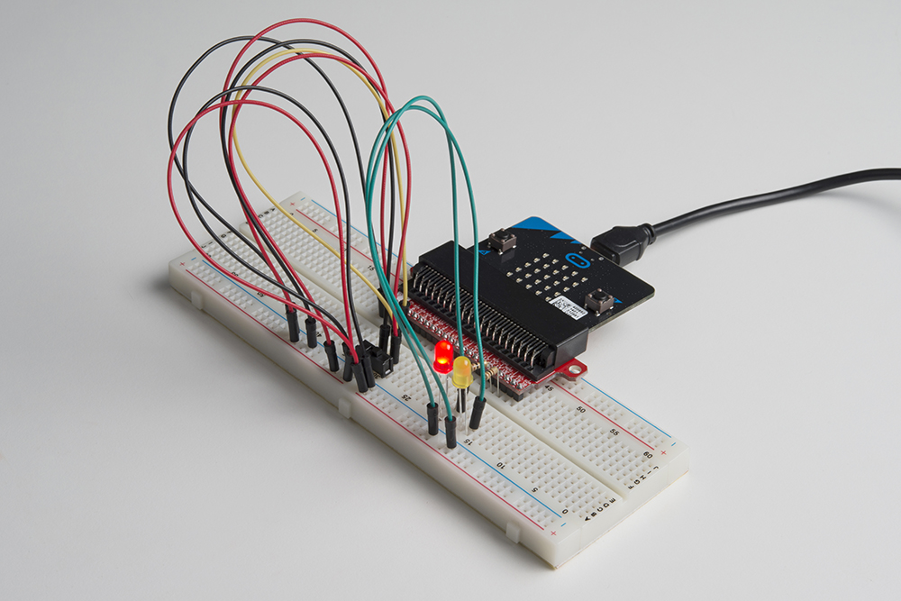
What You Should See
Depending on the state of the switch, a different LED will blink. If you move the switch to connect the signal pin to 3.3V (HIGH), then the LED connected to pin P15 will blink. If you flip the switch and ground the signal pin, then the LED on pin P16 will start blinking and LED 1 will turn off.
Troubleshooting
Light Not Turning On
The wires for the switch are right next to each other. Make sure that signal is in the center with voltage and ground on the outside pins. If you connect ground and voltage, your board will short out and shut down.
Make sure your power LED is on. If it is off, pull the signal wire and see if that changes anything. If you short circuit your micro:bit board, it will turn itself off to protect the circuitry.
Underwhelmed
No worries; these circuits are all super stripped-down to make playing with the components easy, but once you throw them together the sky is the limit.
Experiment 6: Reading a Button Press
Introduction
Up until now, we’ve focused mostly on outputs. Now we’re going to go to the other end of the spectrum and play around with inputs. In Experiment 2, we used an analog input to read the potentiometer. In this experiment, we’ll be reading one of the most common and simple inputs – a push button – by using a digital input. We will use it to cycle through different colors on the RGB.
Parts Needed
You will need the following parts:
- 1x micro:bit
- 1x Micro B USB Cable
- 1x micro:bit Breakout (with Headers)
- 1x Breadboard
- 8x Jumper Wires
- 1x Momentary Push Button
- 1x 10kΩ Resistor
- 1x Common Cathode RGB LED
- 3x 100Ω Resistors
Didn't Get the SIK for micro:bit?
If you are conducting this experiment and didn't get the Inventor's Kit, we suggest using these parts:
Suggested Reading
Before continuing with this experiment, we recommend you be somewhat familiar with the concepts in these tutorials:
Button and Switch Basics
Analog vs. Digital
Introducing the Push Button
A momentary push button closes or completes the circuit only while it is being pressed. The button has four pins, which are broken out into two sets of two pins. When you press down on the button and get a nice "click," the button bridges the two sets of pins and allows current to flow through the circuit.
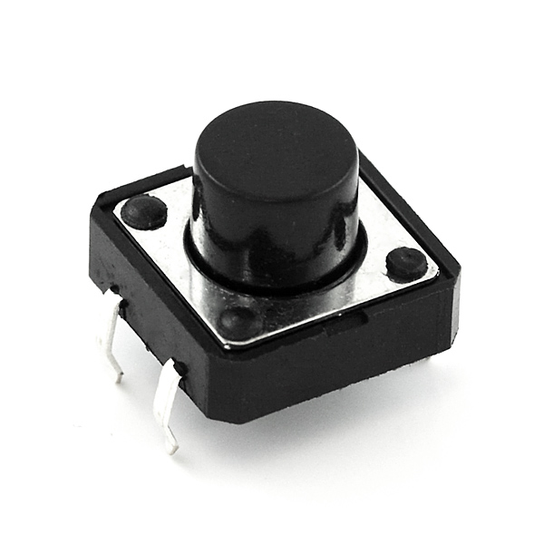
How do you know which pins are paired up? The buttons included in this kit will only fit across the breadboard ditch in one direction. Once you get the button pressed firmly into the breadboard (across the ditch), the pins are horizontally paired. The pins toward the top of the breadboard are connected, and the pins toward the button of the breadboard are connected.
Hardware Hookup
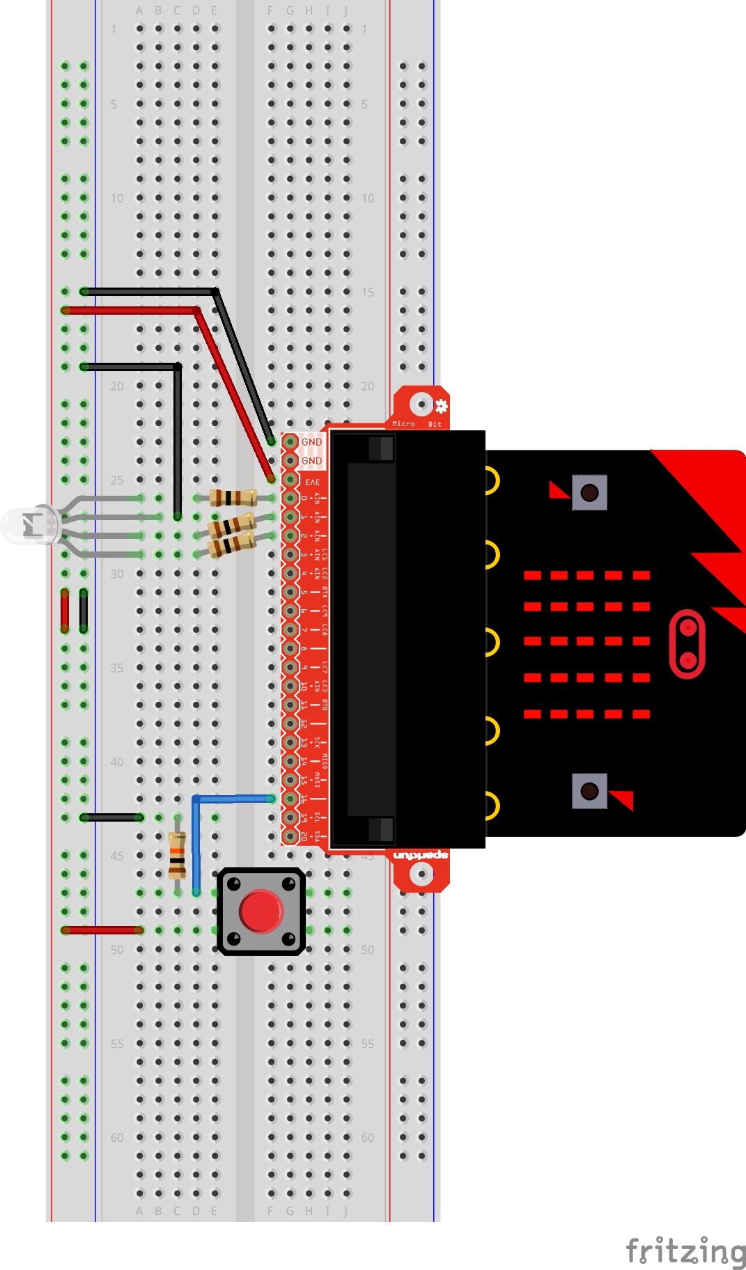
Ready to start hooking everything up? Check out the wiring diagram and hookup table below to see how everything is connected.
| Polarized Components | Pay special attention to the component’s markings indicating how to place it on the breadboard. Polarized components can only be connected to a circuit in one direction. |
Wiring Diagram for the Experiment
Run Your Script
Either copy and paste, or re-create the following code into your own MakeCode editor by clicking the open icon in the upper right-hand corner of the editor window. You can also just download this example by clicking the download button in the lower right-hand corner of the code window.
Code to Note
Let's take a look at the code blocks in this experiment.

Set Pull Pin
When you start your micro:bit, some pins can be set to be naturally on or naturally off. The set pull pin block allows you to set an initial state of a pin by selecting a pin and then its pull state, which is UP, DOWN or NONE.
Set Pin to Emit Event
Just like the button event in Experiment 4 there are events that you can read. But first, you have to set a pin to emit an event. You use the set pin to emit event block to create a type of event for a specific pin to emit or send out when it reaches that state. As an example, we set P16 to emit an EDGE event, which means that it changed from HIGH to LOW or LOW to HIGH.
On Event
Under the Advanced blocks you can find the Control blocks. These are the blocks that are the most complicated to use, but are the most powerful. The On Event block accepts an event type to watch for and a pin that event should happen on. When that specific event is emitted from that pin, it will trigger whatever code is inside of it. Take a moment to look through the list of different events that you can listen for!
if / Else if / Else
Finally, inside of the forever block is a more complex if block, which is an if / if else / else tree. To build this more complex "if" statement, add a standard if / else block into your program. Then click on this small gear in the upper left-hand corner of the block. This will open a tiny interface with more blocks in it. You can drag more else if blocks into the structure here to build your decision tree. Here is what ours looks like:
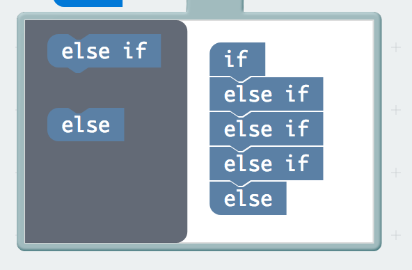
Once you are done rearranging your "if" statement you can close this menu by clicking on the gear again.
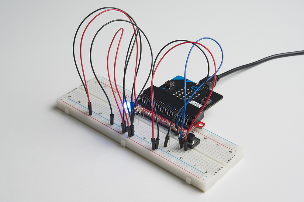
What You Should See
When you press the button, the RGB will turn on to a color. When you press it again, the color will change and another press will change the color once again. Press it one more time, and it will turn off. Every time you press the button, it increments a variable, and then we check against it to set the color. If the variable goes over the value of 2, we reset it to 0, which is off.
Troubleshooting
Light Not Turning On
The push button is square, and because of this it is easy to put it in the wrong way. Give it a 90-degree twist and see if it starts working.
Underwhelmed
No worries; these circuits are all super stripped-down to make playing with the components easy, but once you throw them together the sky is the limit.
Experiment 7: Reading the Temperature Sensor
Introduction
A temperature sensor is exactly what it sounds like --- a sensor used to measure ambient temperature. While there is a temperature sensor built into the micro:bit, we will take this opportunity to learn how to wire an external temperature sensor to measure something that is away from the micro:bit. You will learn how to add an external extension of code to MakeCode that will make using the temperature sensor easier and then put the sensor to good use... measuring the air temperature.
Parts Needed
You will need the following parts:
- 1x micro:bit
- 1x Micro B USB Cable
- 1x micro:bit Breakout (with Headers)
- 1x Breadboard
- 5x Jumper Wires
- 1x TMP36 Temperature Sensor
Didn't Get the SIK for micro:bit?
If you are conducting this experiment and didn't get the Inventor's Kit, we suggest using these parts:
Temperature Sensor - TMP36
SEN-10988Introducing the TMP36 Temperature Sensor
The TMP36 is a low-voltage precision centigrade temperature sensor. It provides a voltage output that is linearly proportional to the Celsius temperature. It also doesn’t require any external calibration to provide typical accuracies of ±1°C at +25°C and ±2°C over the −40°C to +125°C temperature range. The output voltage can easily convert to temperature using the scale factor of 10 mV/°C.
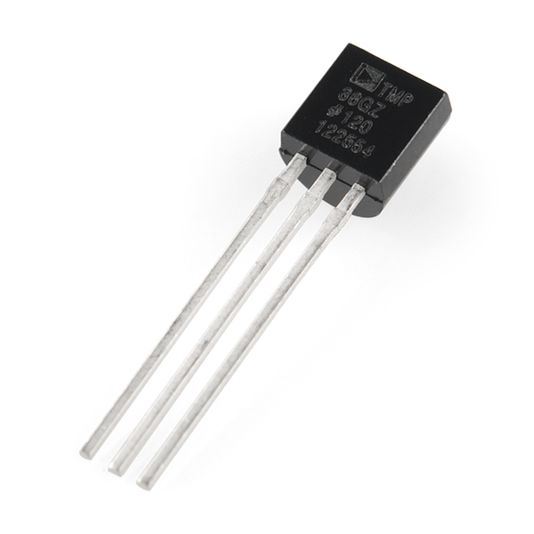
If you are looking at the flat face with text on it, the center pin is your signal pin, the left-hand pin is supply voltage (3.3V in this tutorial), and the right-hand pin connects to ground.
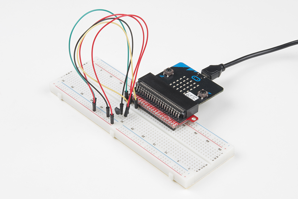
Hardware Hookup
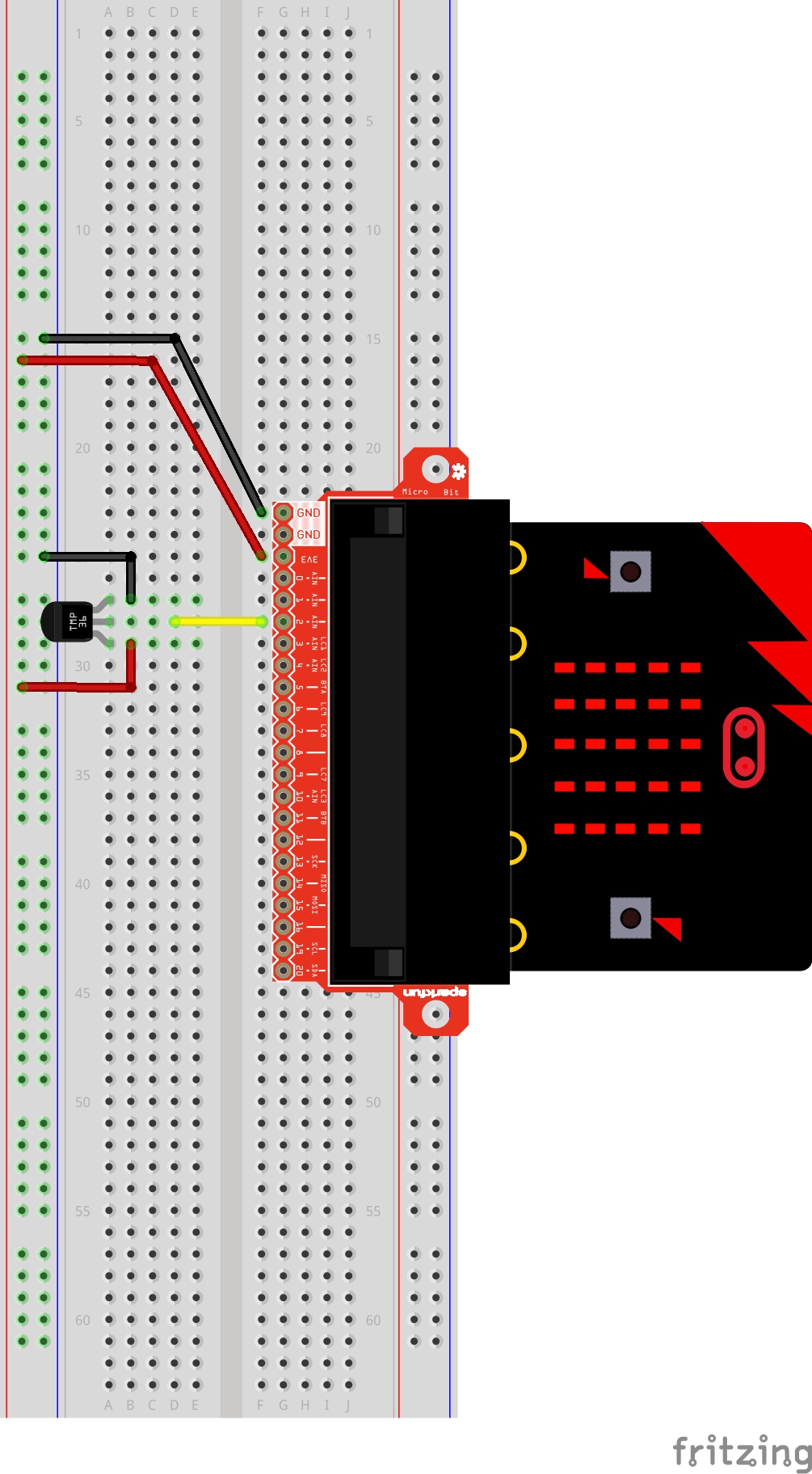
Ready to start hooking everything up? Check out the wiring diagram below to see how everything is connected.
| Polarized Components | Pay special attention to the component’s markings indicating how to place it on the breadboard. Polarized components can only be connected to a circuit in one direction.
The temperature sensor can only be connected to a circuit in one direction. See below for the pin outs of the temperature sensor --- TMP36. |
Wiring Diagram for the Experiment
Run Your Script
Either copy and paste, or re-create the following code into your own MakeCode editor by clicking the open icon in the upper right-hand corner of the editor window. You can also just download this example by clicking the download button in the lower right-hand corner of the code window.
Code to Note
Let's take a look at the code blocks in this experiment.
Adding an External Extension
In MakeCode you can write external pieces of code that allows you to create and use custom blocks for specific applications and/or components that you could use with the micro:bit. We wrote a simple extension for the TMP36 temperature sensor to cut out a lot of complicated math for you to do.
To add a extension to your MakeCode editor first click on Advanced and then Add Extensions....

This will bring up a search box. Feel free to search for different extensions to play with, but for this specific example you need to search for a specific extension. From here you can search for "SparkFun" or "gator-temp," and it should show up as a public extension in the list. Go ahead and click on it.
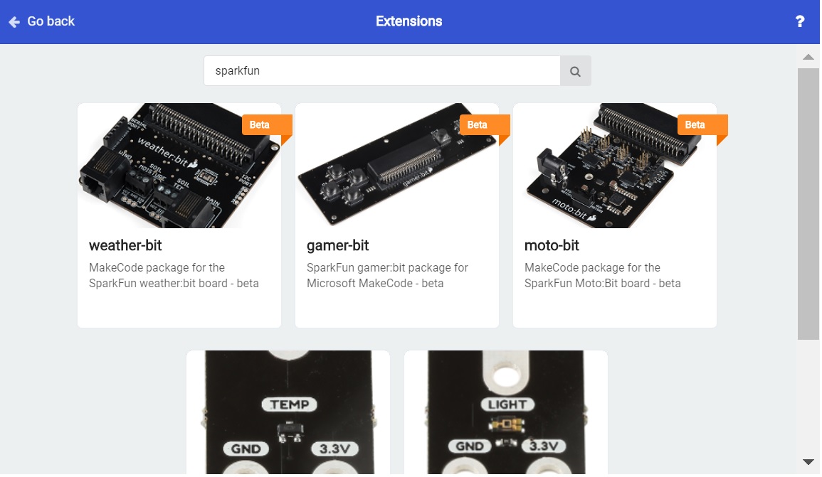
Network request failed error, this is because the extension name was adjusted to the gator-temp. You will need to rebuild any code using the TMP36 extension with the gator-temp extension.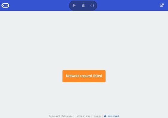
Once you select the gator-temp extension there should be a temperature code block drawer to select from in your blocks menu.
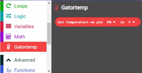
This drawer has only one block in it and that is a block that returns the temperature from a TMP36 sensor connected to a specific pin in Fahrenheit or Celsius.
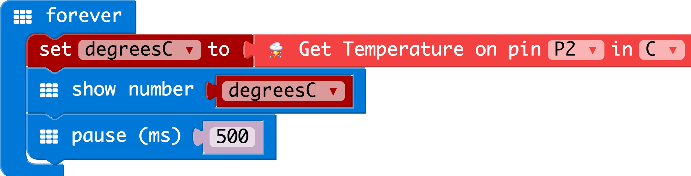
Show Number
The Show Number block accepts a number value and then displays it on the LED array. That's it! Pretty simple. If the number is longer than a single digit, it will automatically scroll the value for you.
Get Temperature on Pin
The only block in the TMP36 extension is the Get Temperature on Pin block. This block does all of the hard math for you to get an accurate temperature from the TMP36 sensor. You select the pin the sensor is connected to and what unit of measure you would prefer (Fahrenheit or Celsius). If you want, you can also get the raw 10 bit value as well (0-1023).
What You Should See
When your micro:bit turns on, the temperature reading from the TMP36 temperature sensor will be displayed and scrolled across the LED array.
Troubleshooting
Temperature Value is Unchanging
Try pinching the sensor with your fingers to heat it up or pressing a bag of ice against it to cool it down.
Temperature Reads Random 5-Digit Number
If you see an output with "65525", "65533", "65527", etc. on the LEDs, the issue might be due to a loose (or possibly shorted) connection between the 3.3V pin and the TMP36's voltage input pin. The analog pin will probably start reading random values or there is a slight current draw to the temperature sensor from the micro:bit. Make sure that you check your connections by ensuring that there are no loose connections or pins touching where they should not. If you are using alligator clips, make sure that the connection is secure as well and that there are no shorts (try sliding the sheath around the alligator clips for more insulation).
Temperature Sensor is Really Hot!
You have wired it backward! Unplug your micro:bit immediately, let the sensor cool down, and double-check your wiring. If you catch it soon enough, your sensor may not have been damaged and may still work.
Experiment 8: Using a Servo Motor
Introduction
This experiment is your introduction to the servo motor, which is a smart motor that you can tell to rotate to a specific angular location. You will program it to rotate to a series of locations, then sweep across its full range of motion, and then repeat.
Parts Needed
You will need the following parts:
- 1x micro:bit
- 1x Micro B USB Cable
- 1x micro:bit Breakout (with Headers)
- 1x Breadboard
- 5x Jumper Wires
- 1x Servo
Didn't Get the SIK for micro:bit?
If you are conducting this experiment and didn't get the Inventor's Kit, we suggest using these parts:

Suggested Reading
Before continuing with this experiment, we recommend you be familiar with the concepts in the following tutorial:
Pulse Width Modulation
Hobby Servo Tutorial
Introducing the Servo Motor
Unlike the action of most motors that continuously rotate, a servo motor can rotate to and hold a specific angle until it is told to rotate to a different angle. You can control the angle of the servo by sending it a PWM (Pulse Width Modulation) pulse train; the PWM signal is mapped to a specific angle from 0 to 180 degrees.

Inside of the servo there is a gearbox connected to a motor that drives the shaft. There is also a potentiometer that gives feedback on the rotational position of the servo, which is then compared to the incoming PWM signal. The servo adjusts accordingly to match the two signals.
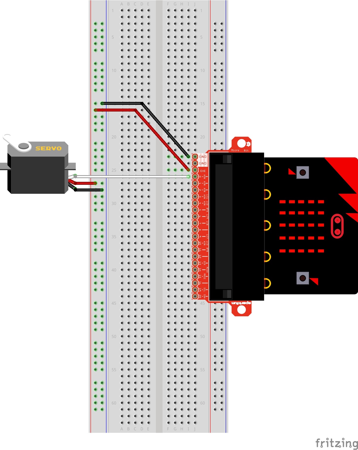
In this experiment, the servo is powered through 3.3 volts on the red wire and ground on the black wire; the white wire is connected to pin P0.
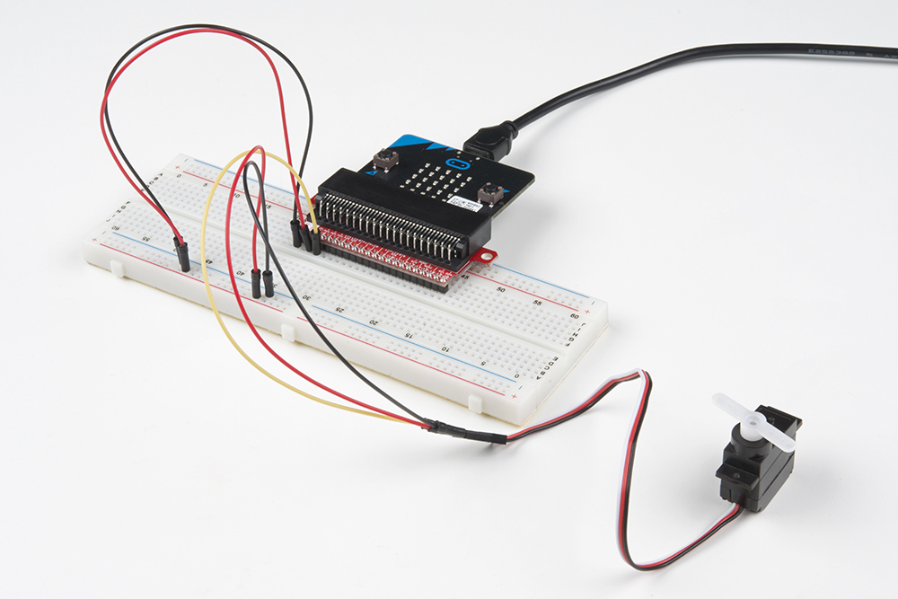
Hardware Hookup
Ready to start hooking everything up? Check out the wiring diagram below to see how everything is connected.
| Polarized Components | Pay special attention to the component’s markings indicating how to place it on the breadboard. Polarized components can only be connected to a circuit in one direction. |
Connect 3x jumper wires to the female 3-pin header on the servo. This will make it easier to breadboard the servo.
Wiring Diagram for the Experiment
Run Your Script
Either copy and paste, or re-create the following code into your own MakeCode editor by clicking the open icon in the upper right-hand corner of the editor window. You can also just download this example by clicking the download button in the lower right-hand corner of the code window.
Code to Note
Let's take a look at the code blocks in this experiment.
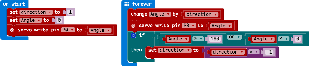
Set "Direction To"
In the On Start block we set the direction variable to 1. This value will be toggled between 1 and -1 to determine the direction we want the servo to sweep.
Servo Write
We use the Servo Write block to control a servo connected to a specific pin to rotate to a specific angle we pass it in degrees. We use a variable we have labeled as degrees. You can use this command to just write any angle between 0 and 180 to a servo motor at any time, but do remember to add a small pause to make sure that you give it enough time to respond before moving to the next angle.
Change by
If you want to increment or decrement a given variable by a certain value, which is positive or negative, you use the Change by block. You can select the variable you want to change and then the value you want to increment by (positive value) or decrement by (negative value). We increment the angle by 1 degree using this block.
Set "Direction to Direction x -1"
To change the direction of the servo once it reaches 0 or 180, we do some fancy math to multiply the direction variable by -1 to toggle it from a positive value to a negative number or a negative number to a positive value. That way when we use the change by block, the number is positive or negative.
What You Should See
When powered up you should see the servo move to a single location (0 degrees) and then start to sweep to 180 degrees back and forth until you turn it off or tell it to go to a different angle.
Troubleshooting
Servo Not Twisting
Even with colored wires, it is still shockingly easy to plug a servo in backward. This might be the case.
Still Not Working
A mistake we made a time or two was simply forgetting to connect the power (red and black wires) to 3.3 volts and ground (GND).
Experiment 9: Using a Buzzer
Introduction
In this experiment, we will again bridge the gap between the digital world and the analog world. We'll be using a piezo buzzer that makes a small "click" when you apply voltage to it (try it!). By itself that isn't terribly exciting, but if you turn the voltage on and off hundreds of times a second, the piezo buzzer will produce a tone. And if you string a bunch of tones together, you've got music! This circuit and set of code blocks will create a simple sound machine.
Parts Needed
You will need the following parts:
- 1x micro:bit
- 1x Micro B USB Cable
- 1x micro:bit Breakout (with Headers)
- 1x Breadboard
- 14x Jumper Wires
- 1x Piezo Buzzer
- 2x Momentary Push Buttons
- 2x 10kΩ Resistors
Didn't Get the SIK for micro:bit?
If you are conducting this experiment and didn't get the Inventor's Kit, we suggest using these parts:
Introducing the Piezo Buzzer
The buzzer is a small component with a piece of metal in it that moves when you apply a voltage across it. This motion causes a small sound, or "click."

If you turn the voltage on and off fast enough, you get different beeps, squeals, chirps and buzzes. You will use PWM to control the speed of turning the piezo on and off --- and, in turn, the audio frequency coming out of the buzzer. Adjusting the PWM enables you to get legitimate notes out of the buzzer.
If you flip the buzzer over and look at the bottom, you will see that one pin has a (+) next to it. That pin gets connected to a signal from the P0 pin. The other pin should be connected to ground.
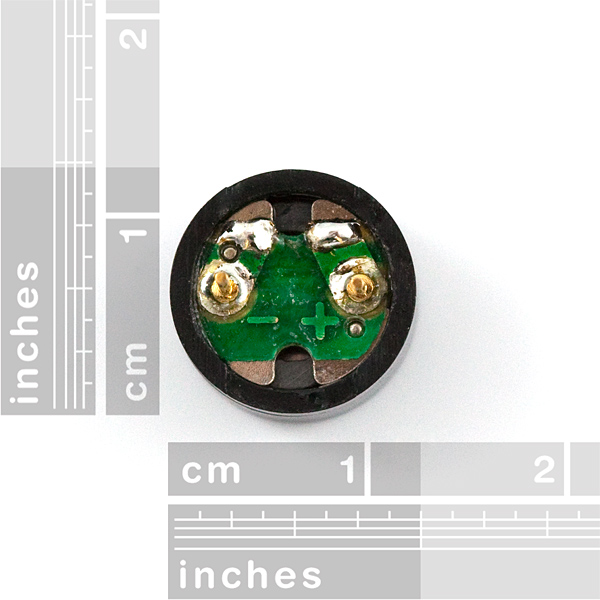
For users with a micro:bit v2, there is also a built-in piezo buzzer. We will be focusing on wiring an external piezo buzzer.
Hardware Hookup
Ready to start hooking everything up? Check out the wiring diagram below to see how everything is connected.
| Polarized Components | Pay special attention to the component’s markings indicating how to place it on the breadboard. Polarized components can only be connected to a circuit in one direction. |
Wiring Diagram for the Experiment

Run Your Script
Either copy and paste, or re-create the following code into your own MakeCode editor by clicking the open icon in the upper right-hand corner of the editor window. You can also just download this example by clicking the download button in the lower right-hand corner of the code window.
For users with micro:bit V1, simply remove the
set built-in speaker code block before compiling and downloading the program in the editor. Of course, you can head back to the old code as well. Code to Note
Let's take a look at the code blocks in this experiment.
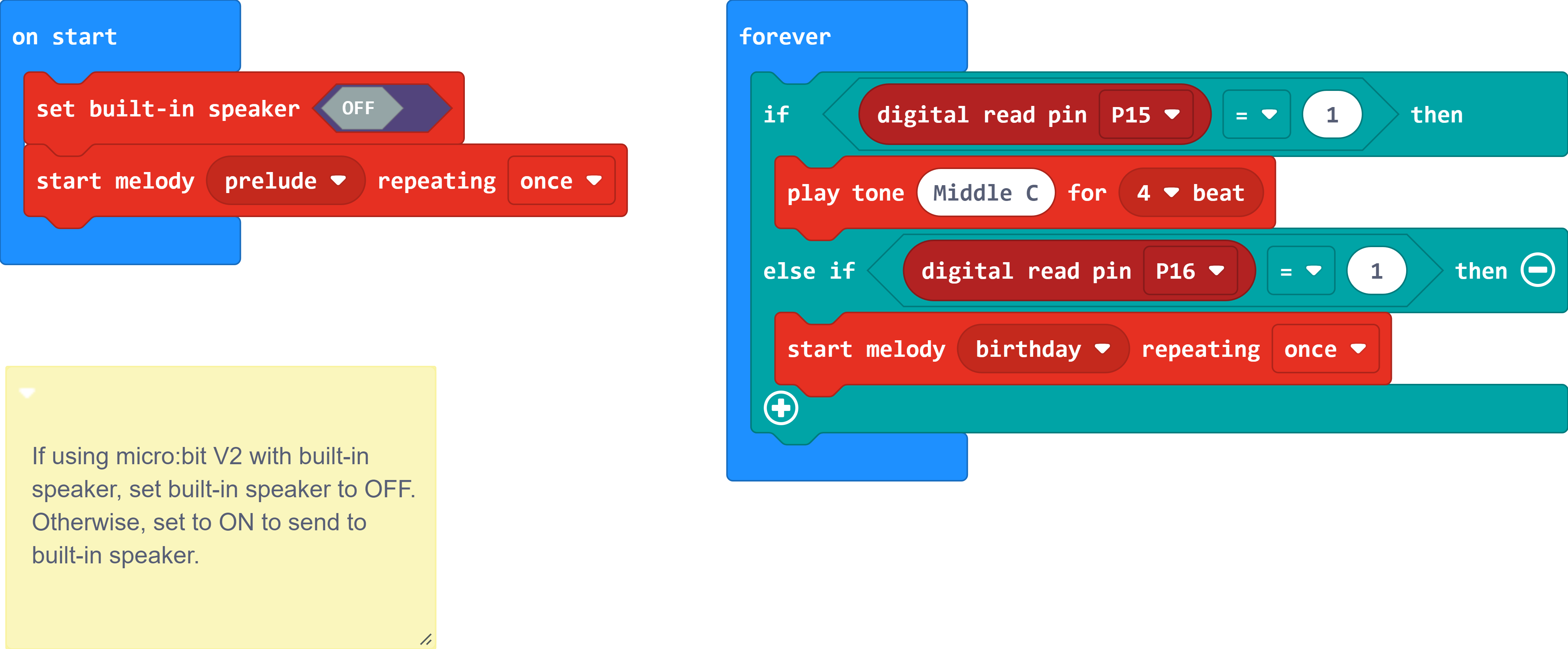
Set Built-in Speaker
The set built-in speaker sets the output for the speaker. By default, this outputs to the built-in speaker on micro:bit v2. If this block is also not defined, the micro:bit V2 will also output to the built-in speaker instead of pin 0. Setting it to OFF will output the signal to an external piezo buzzer on pin 0.
Start Melody Repeating
The Start Melody Repeating block takes all of the frustration out of getting music out of a microcontroller. It is as simple as selecting one of a number of songs that are preprogrammed into MakeCode and how many times you want it to repeat and you are done! Note that when a melody is playing no other code can run, this is called "blocking" code and has to be accounted for you in your program.
Play Tone for
The play tone for block is pretty standard if you are used to making sound with other microcontrollers. For example, tone() function in Arduino is pretty much the same as this block. The play tone for block accepts a note that you would like the buzzer to produce and the length of time in beats per second that you would like it to play. So if you are a musician, you are golden to write horrible robot music for your friends!
What You Should See
What you should see --- well, nothing! What you should hear --- a song should start as soon as the program starts to run on your micro:bit! When that song is done you can press one of the two buttons, and another song will start. Each button has its own song, and there's another song if you press both buttons at the same time. Enjoy your sound machine and feel free to swap out the song of your choice!

Try wiring a potentiometer between the buzzer and pin 0. Adding a potentiometer will adjust the volume. Flipping the set built-in speaker to the ON position will also output sound to the built-in speaker.
Troubleshooting
No Sound
Given the size and shape of the piezo buzzer, it is easy to miss the right holes on the breadboard. Try double-checking its placement.
Also, double check to make sure the push button is wired correctly. If you miswired it, then the circuit will never be completed even if you press the button or not.
Feeling Let Down and Deserted
Create your own song using just the tone blocks rather than the standard song options given from the start melody block.
Experiment 10: Using the Accelerometer
Introduction
In this experiment you will look at combining the use of the accelerometer on the micro:bit to measure the orientation of the micro:bit and use it to control the angle of a servo.
Ready to shake, rattle and roll?
Parts Needed
You will need the following parts:
- 1x micro:bit
- 1x Micro B USB Cable
- 1x micro:bit Breakout (with Headers)
- 1x Breadboard
- 5x Jumper Wires
- 1x Servo
Didn't Get the SIK for micro:bit?
If you are conducting this experiment and didn't get the Inventor's Kit, we suggest using these parts:
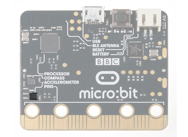
Introducing the Accelerometer
The accelerometer is a component that you won't find in the kit's bag of parts. Why? Because it is on the micro:bit itself! On the back of the micro:bit you can see a number of small chips. One of them is the accelerometer. The micro:bit has an onboard accelerometer that measures gravitational force. Depending on the version that you have, the accelerometer and compass can be on separate ICs or combined into a single IC.
 |
|
| v1.0 w/ Accelerometer on Sepearate IC | v1.5 w/ Combined Accelerometer and Magnetometer |
An accelerometer is a sensor that measures the gravitational forces pulling on it in all three dimensions of the chip's X, Y and Z axes.
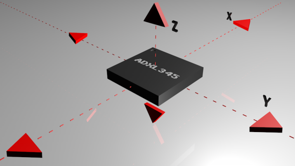
Not only can an accelerometer measure the raw forces pulling on the chip and the object that the chip is sitting on, but it can also detect steps, shakes and other motions that have a specific pattern. On top of that, you can use an accelerometer to simply detect the orientation that the device is in. Did you ever wonder how your phone knows when you turn it from portrait to landscape? It is all because of the accelerometer in your phone!
Hardware Hookup
Ready to start hooking everything up? Check out the wiring diagram below to see how everything is connected.
| Polarized Components | Pay special attention to the component’s markings indicating how to place it on the breadboard. Polarized components can only be connected to a circuit in one direction. |
Wiring Diagram for the Experiment
Run Your Script
Either copy and paste, or re-create the following code into your own MakeCode editor by clicking the open icon in the upper right-hand corner of the editor window. You can also just download this example by clicking the download button in the lower right-hand corner of the code window.
Code to Note
Let's take a look at the code blocks in this experiment.

Acceleration
The acceleration block can be found under the input blocks group. This block returns the force of gravity pulling on a specific axis of the micro:bit (X, Y or Z) and represents that value as a range of numbers between -1023 and 1023. In this case, we measure the X axis, which is the side-to-side tilt of the micro:bit. If you tilt the micro:bit all the way to the left, you will get a -1023 value and all the way to the right is positive 1023.
Map
The map block looks intimidating, but it is one of the most useful blocks in MakeCode. The map block takes a given variable that has a known range --- in this case -1023 to 1023 --- and "maps" or scales that value range to another given range. The given range we want is 15 to 165, which is a good safe range of rotation for the servo. So, in the end -1023 ends up to equal 0, and 1023 ends up as 165 from the map block.
What You Should See
At the beginning of the program the servo should move to 90 degrees and then react to the orientation of the micro:bit. If you hold the micro:bit flat, the servo will be at 90 degrees. Then if you tilt the servo to the left, it will move less than 90 degrees toward the value of 15. If you move it to the right, the servo will move toward 165.
Troubleshooting
This Seems Backward
You may be holding the micro:bit in a different orientation. Flip it around and try again!
Servo Isn't Working
Double-check your wiring! Remember, red to 3.3 volts, black to ground, and white to signal.
Experiment 11: Using the Compass
Introduction
This experiment is just plain fun! Have you ever used a compass? Are you a little confused in terms of which direction to go? Fear not! We will build a digital compass that will keep you on track to the North Pole using the micro:bit's onboard compass chip!
Parts Needed
You will need the following parts:
- 1x micro:bit
- 1x Micro B USB Cable
- 1x micro:bit Breakout (with Headers)
- 1x Breadboard
- 4x Jumper Wires
- 2x LEDs
- 2x 100Ω Resistors
Didn't Get the SIK for micro:bit?
If you are conducting this experiment and didn't get the Inventor's Kit, we suggest using these parts:
Introducing the Compass (Magnetometer)
In the previous experiment you learned about the accelerometer, which measured gravity. The compass, or technically the magnetometer, measures a magnetic field. Magnetic fields come in different sizes, but the biggest is the one produced by Earth itself, which is why compasses work.
The micro:bit has an onboard compass (a.k.a. a magnetometer) that can detect its orientation using Earth's magnetic field. Depending on the version that you have, the accelerometer and compass can be on separate ICs or combined into a single IC.
 |
|
| v1.0 w/ Magnetometer On Separate IC | v1.5 w/ Combined Accelerometer and Magnetometer |
The magnetometer detects magnetic north and then represents your heading in degrees with north being 0 degrees, east being 90 degrees, south being 180 degrees and west being 270. Pretty cool! Now let's put this compass to good use!
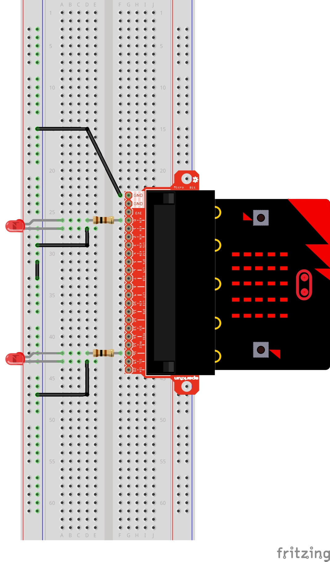
Hardware Hookup
Ready to start hooking everything up? Check out the wiring diagram below to see how everything is connected.
| Polarized Components | Pay special attention to the component’s markings indicating how to place it on the breadboard. Polarized components can only be connected to a circuit in one direction. |
Wiring Diagram for the Experiment
Run Your Script
Either copy and paste, or re-create the following code into your own MakeCode editor by clicking the open icon in the upper right-hand corner of the editor window. You can also just download this example by clicking the download button in the lower right-hand corner of the code window.
Code to Note
Let's take a look at the code blocks in this experiment.
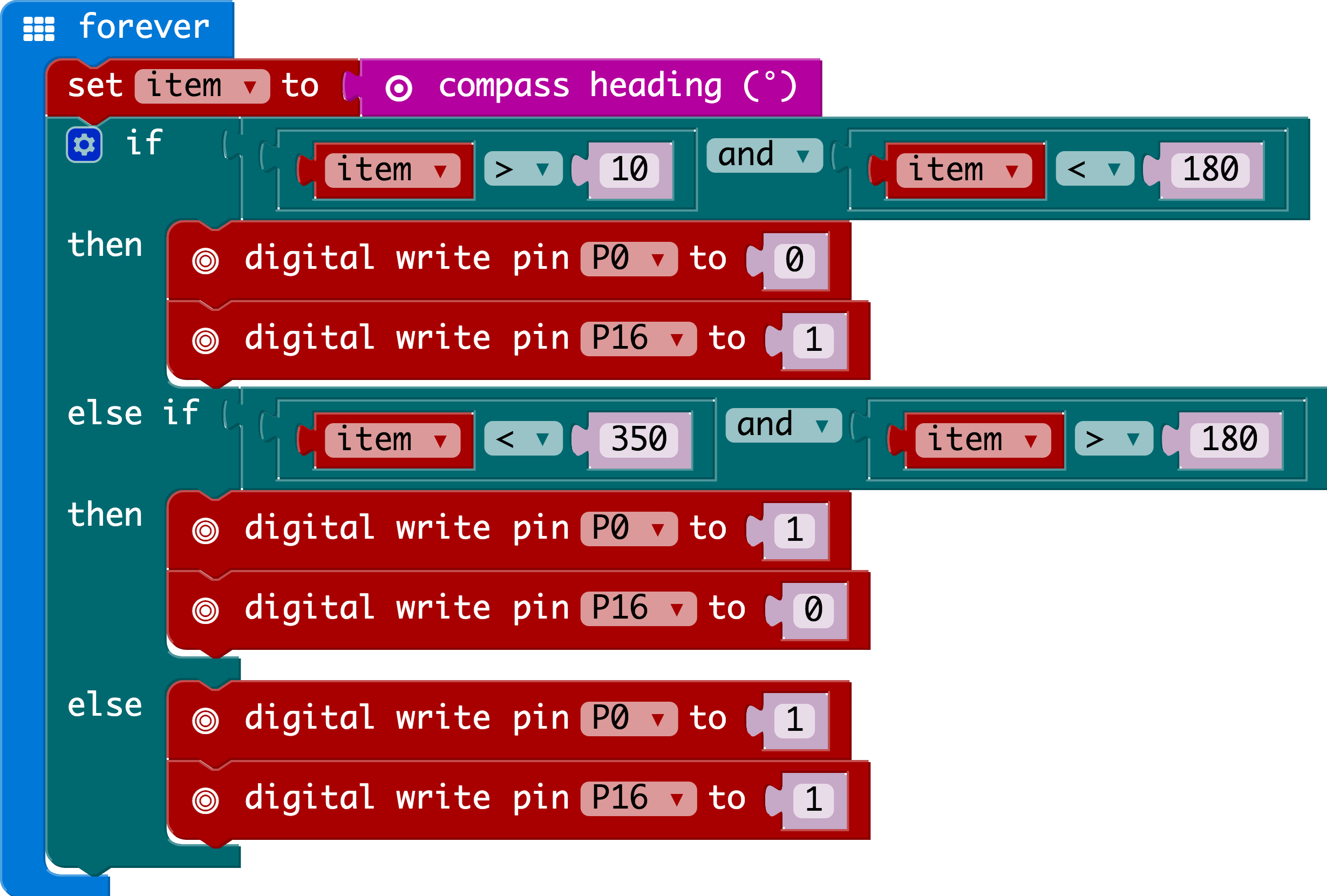
Compass Heading
The compass heading block returns the heading that you are facing if you are holding the micro:bit flat with the pins toward you. Zero degrees is north. We store this heading in a variable called item.
And
Much of the rest of this code is straightforward, but the logical and block is used. This combines two logical statements into one statement that returns true when both of the other statements are true and only true.
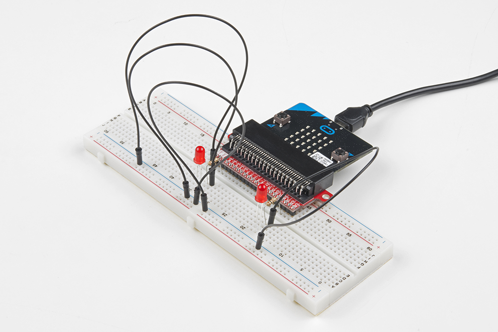
What You Should See
When your code is loaded you will first see instructions on the micro:bit LED array. The instructions will ask you to draw a circle, move the micro:bit around until all of the part of the circle have been added and it displays a smiley face. This process is to calibrate the micro:bit's magnetometer with its surroundings. The LEDs will start to turn on --- one or the other, or both. While standing still, rotate in the direction of the LED that is on. When both LEDs are lit, you are facing generally north (if you are outside)! You now have a compass that helps you find north, or any other direction you choose if you change the code!
Troubleshooting
Not Really North?
You may have a motor or magnet close by! The magnetometer is sensitive to all magnetic fields, including ones that may be produced by other electronics, metal, or even...a magnet.
LEDs Seem Backward
You might have your logical statement backward! Try flipping your greater than to less than, or the other way around.
Resources and Going Further
We produce a number of other kits and carrier boards that you can hook up to your micro:bit to help take your projects to the next level. Here is some further reading that may help you along in learning more about the world of electronics.
For more information on our micro:bit ecosystem, check out these tutorials:
micro:climate Kit Experiment Guide
micro:bot Kit Experiment Guide
micro:arcade Kit Experiment Guide
micro:bit Breakout Board Hookup Guide
Or try using MicroPython with micro:bit!
Getting Started with MicroPython and the SparkFun Inventor's Kit for micro:bit
For more information on basic electronic concepts, check out these tutorials: