Hobby Servo Tutorial
 MikeGrusin,
  Byron J.
 Introduction
Servo motors are an easy way to add motion to your electronics projects. Originally used in remote-controlled cars and airplanes, they now crop up in all sorts of other applications. They're useful because you can precisely control the positioning of these motors. Instruct them where to point, and they'll do it for you.
An ordinary DC motor has two hookup wires and simply turns continuously when power is applied. If you want it to spin in the opposite direction, you'll need to reverse the power. And if you want to know how far it has turned, you'll need to devise a way to measure that.
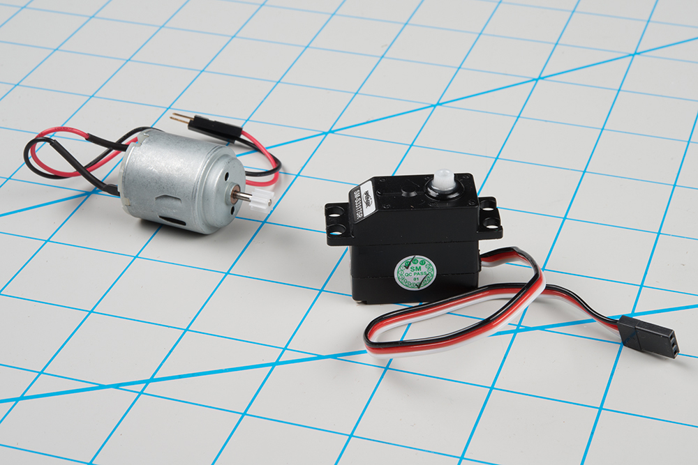
In contrast, you instruct a servomotor where to turn using carefully-timed pulses. The servo has three wires: power, ground, plus a third wire to carry the command pulses.
Suggested Reading
- An Introduction to Motors.
- Some background on Pulse Width Modulation.
Servo Motor Background
In the most generic sense, a “servomechanism” (servo for short) is a device that uses feedback to achieve the desired result. Feedback control is used in many different disciplines, including speed, position, and temperature.
In the context we are discussing here, we are talking about hobby or radio-control servo motors. These are small motors primarily used for steering radio-controlled vehicles. Because the position is easily controllable, they are also useful for robotics and animatronics. However, they shouldn’t be confused with other types of servo motors, such as the large ones used in industrial machinery.
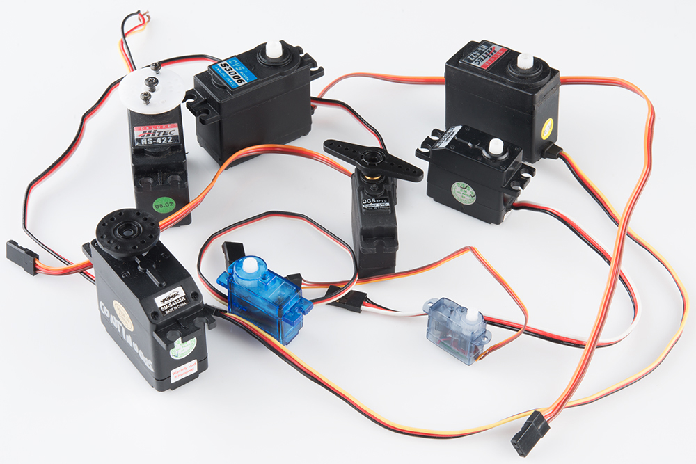
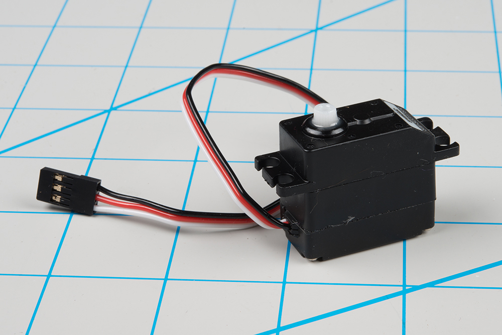
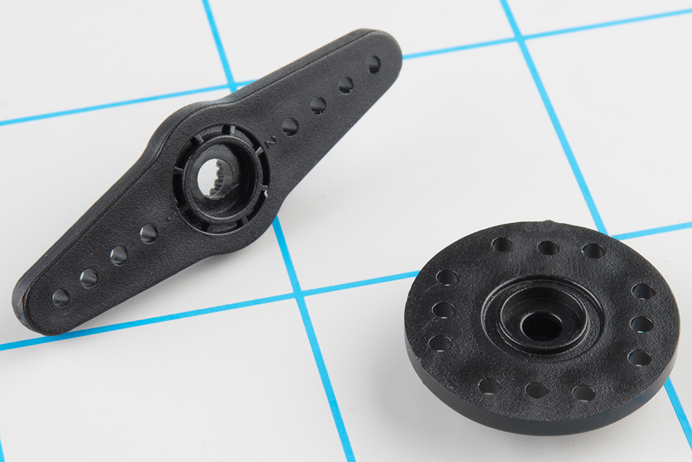
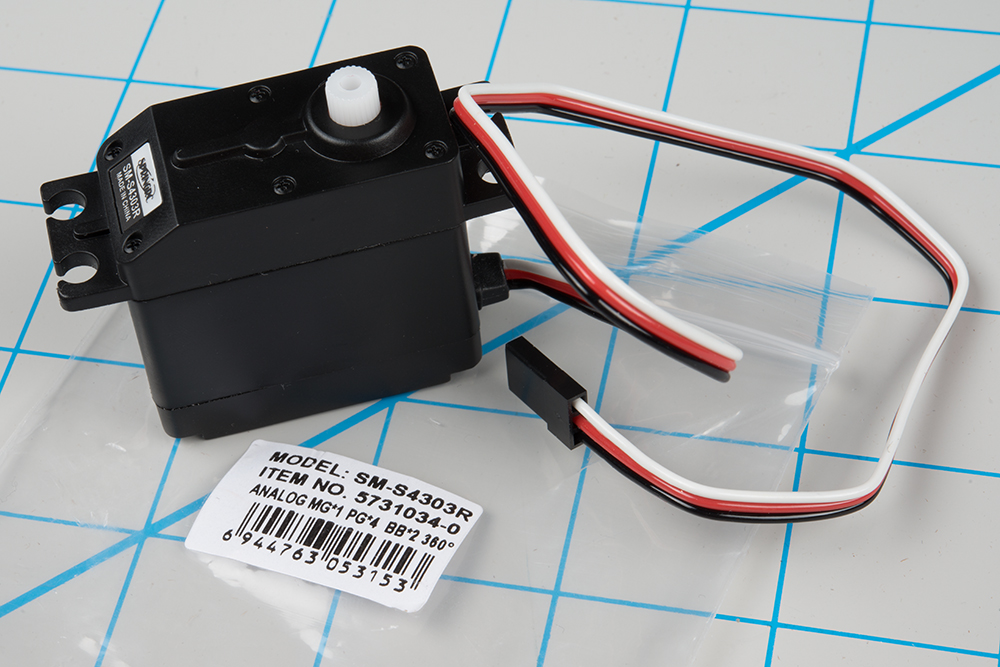
RC servos are reasonably standardized - they are all a similar shape, with mounting flanges at each end, available in graduated sizes, from "ultra-nano" to "giant". Servos often come with multiple attachments, such as wheels or levers, known as “horns”, than can be attached to the shaft, to fit the device they are operating.
Electrical Connection
Most hobby servos use a standard type of 3-pin plug, with the same control signaling, which makes RC servos reasonably interchangeable.
The connector is a female, 3-pin, 0.1" pitch header. One thing that can be confusing is that the wiring color code isn't always consistent -- there are several color codes at play. The good news is that the pins are usually in the same order, just that the colors are different.
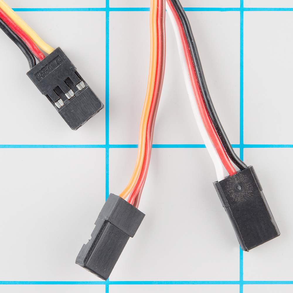
The table below summarizes common color schemes. A useful mnemonic is that the most drab color (black or brown) is usually ground, and red is usually the power supply.
| Pin Number | Signal Name | Color Scheme 1 (Hitec) |
Color Scheme 2 (JR) |
Color Scheme 3 (Futaba) |
|
| 1 | Ground | Black | Brown | Black | |
| 2 | Power Supply | Red | Brown | Red | Red |
| 3 | Control Signal | Yellow | White | Orange | White |
Control signal
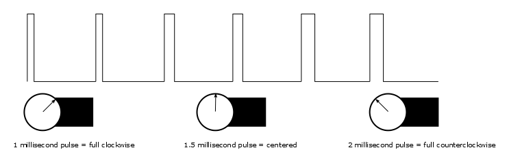
The third pin of the servo connector carries the control signal, used to tell the motor where to go. This control signal is a specific type of pulse train. The pulses occur at a 20 mSec (50 Hz) interval, and vary between 1 and 2 mSec in width. The Pulse Width Modulation hardware available on a microcontroller is a great way to generate servo control signals.
Common servos rotate over a range of 90° as the pulses vary between 1 and 2 mSec -- they should be at the center of their mechanical range when the pulse is 1.5 mSec.
Powering Servos
In RC vehicles, the nominal battery voltage is 4.8V. It will be somewhat higher after a charge, and it will droop as the batteries discharge. As the voltage drops, the available torque also drops -- if you've driven RC vehicles, you're no doubt familiar with the loss of control that occurs as the batteries get weaker. It starts to feel sluggish just before it dies.
If you're not using batteries, the 5VDC available from a garden variety power supply is a good option. If you're using an Arduino or other microcontroller (such as the SparkFun Servo Trigger) to control your motor, the absolute maximum supply voltage that should be applied is 5.5 VDC.
Regardless of how you're powering them, it's worth noting that the current consumed by the motor increases as the mechanical loading increases. A small servo with nothing attached to the shaft might draw 10 mA, while a large one turning a heavy lever might draw an Ampere or more! If your power supply isn't up to the task, a straining or stalled servo can cause the supply to sag, which may have other unpredictable repercussions, such as causing microcontrollers to reset.
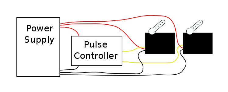
Additionally, if you've got multiple servos, or in applications where the motors are moving non-trivial loads, it’s best to use heavy gauge wires and give each servo a direct connection to the power supply, rather than daisy-chaining power from one to the next. This configuration is commonly known as “star power.” If one servo causes the power rail to droop, it's less likely to effect the others when each has a direct connection.
When in doubt, grab a multimeter, measure the current consumed, and check whether VCC sags when the servos are turning.
Show Me The Guts
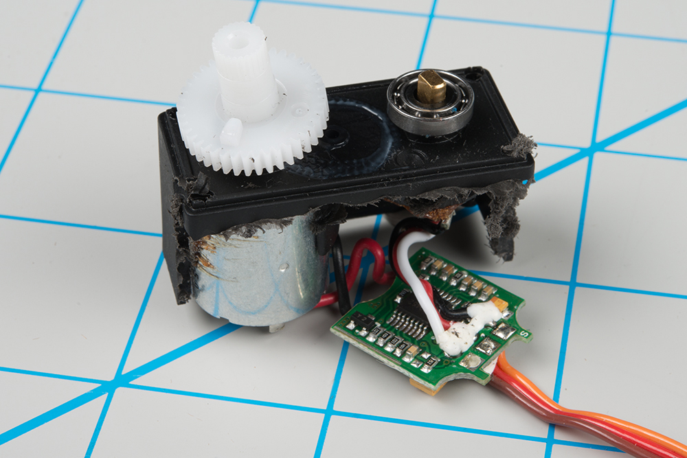
Internally, the mechanism of a servo motor uses a potentiometer attached to the rotating shaft to sense the position. It measures the width of the incoming pulse and applies current to the motor to turn the shaft, until the potentiometer indicates that the position corresponds to the incoming pulse width. This is a form of feedback control. The motor has received the desired position from the pulse width, and the actual shaft position is fed back to the circuit via the potentiometer. It compares the desired value to the actual value and drives the motor in the direction that causes actual to match desired.
Here are the insides of a servo that's been dissected. You can see the gears, DC motor, position potentiometer, and a small PCB. The PCB has a chip on one side, possibly a small microcontroller or specialized servo IC.
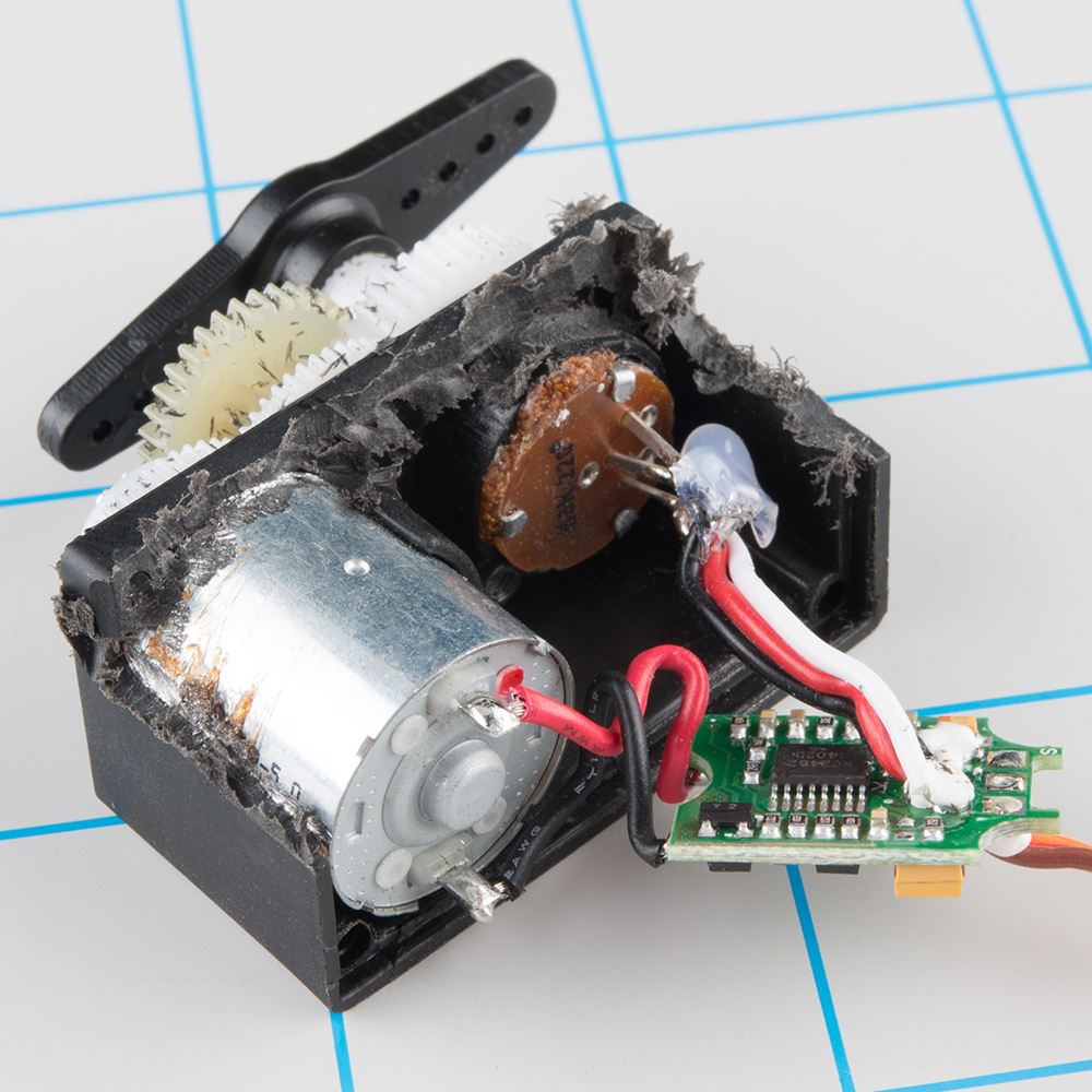
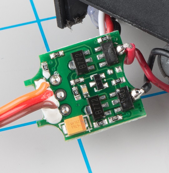
The other side of the PCB has some discrete transistors, probably in an H-bridge configuration, which allow the controller to steer current through the motor in either direction, for both clockwise and counterclockwise rotation.
A Handful of Distinctions
When you're shopping for servos for your project, there are several parameters that you'll want to keep in mind.
Range Constraints
The 1-to-2 millisecond pulse range is more of a convention than a hard-and-fast standard. Some servo motors respond to even shorter or longer pulses with an extended range of motion.
Be warned that there is a risk -- this expanded range of motion isn't universal. Some servos are mechanically limited to 90° rotation. Attempting to drive them beyond their limits can cause damage, such as stripped gears. The servo that we see dismantled here suffered exactly that fate.
Position vs. Continuous Rotation
Moving even further from the 90° range, there are also full rotation, continuous rotation, or simply 360° servos. As the name states, the shaft turns continuously, making them useful as drive motors. Visually, they look just like regular servos.
Rather than controlling position, the continuous rotation servo translates the 20 mSec pulse-train signal into the rotational speed and direction of the shaft. Otherwise, they're very similar to regular RC servos -- they use the same power supply, control signals, 3-pin connector, and are available in the same sizes as RC servos.
The overall speed is relatively low -- around 60 RPM is a common maximum rate -- if you need higher rotation speed, servos aren't the best fit -- DC gearmotors or brushless DC motors are more likely candidates, but they aren't directly compatible with servo control signals.
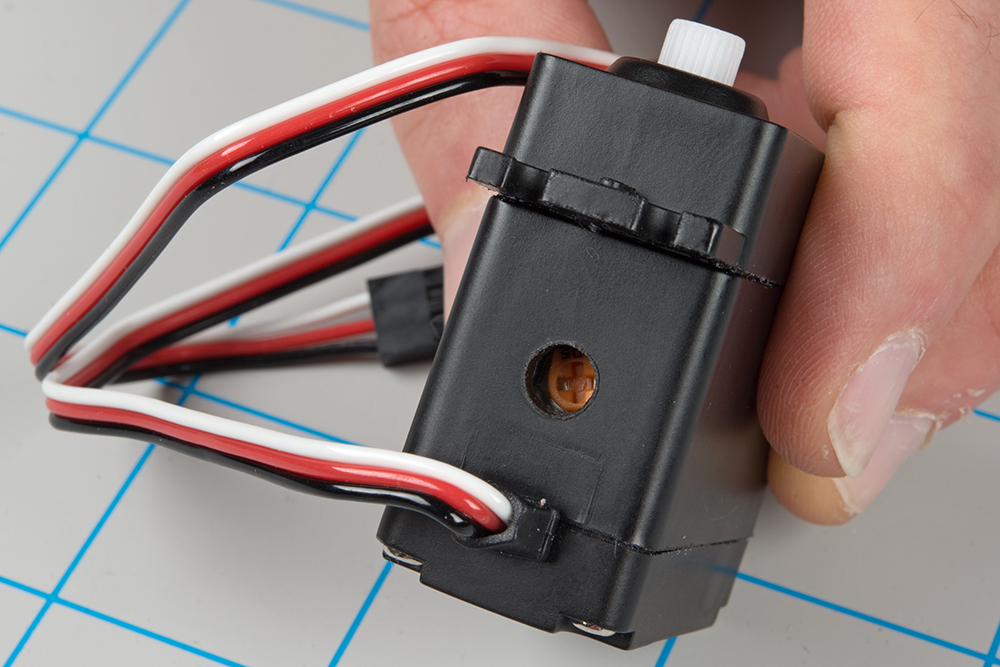
On closer inspection, continuous rotation servos have one small difference from regular servos: they usually have a "nulling" trimpot, used to adjust their response to the control signal. It's typically set so that a 1.5 mSec pulse stops the motor. Shorter pulses will cause it to turn counterclockwise, and longer pulses cause it to turn clockwise.
Analog vs. Digital
The pulse-controlled servos we're discussing here are analog. There are also digitally-controlled servos that use a high-speed pulse train, and have a serial communication interface that allows more detailed configuration, typically with parameters that are tailored to RC vehicles.
Plastic vs. Metal Gears
One last thing to look at when considering a servo is the type of gears it contains.
Inexpensive servos (such as the one dismantled here) usually contain molded plastic gears, while more expensive servos have metal gears. Plastic gears are more likely to strip if the motor is jammed or overloaded. The old adage rings true: you get what you pay for.

Deploying Servos
Traditional RC Application
As we stated in the introduction, the usual application of hobby servo motors is for steering radio-controlled vehicles.
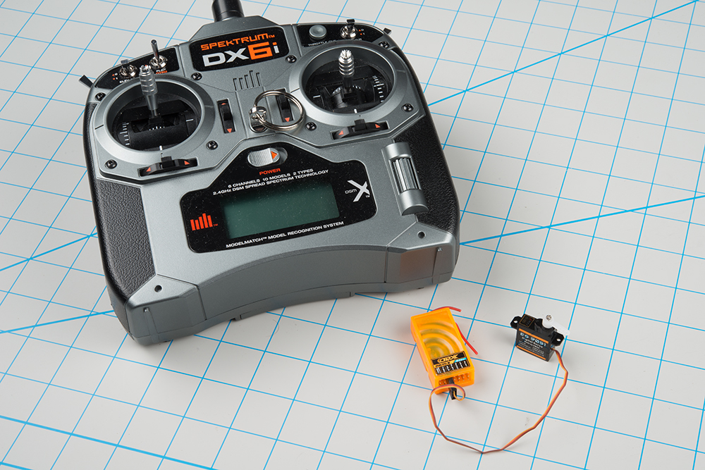
RC vehicles are controlled with a transmitter unit -- the box with the joysticks and antenna. The transmitter sends control information to receiver modules (the orange box shown above), which connect to the servo motors. When the sticks on the transmitter are moved, the receiver generates corresponding pulses, instructing the motors to move.
Configuring older RC craft required a fair amount of patience, because adjusting the servos meant careful mechanical tweaking of the servo horns, mechanical linkages, and trim controls on the transmitter. Modern transmitters and receivers are microcontroller-based, tweaked through the LCD on the transmitter, or even a computer interface.
Controlling a Servo with Arduino
Because they move on command, servo motors are an easy way to add motion to any project. If you're working with an Arduino-compatible platform, the Arduino servo library provides a ready-to-go servo pulse generation solution.
Suggested Materials
To build this example, you'll need the following materials.


Hardware Hookup
Hooking a servo to a RedBoard is pretty straightforward. It only requires 3 connections.
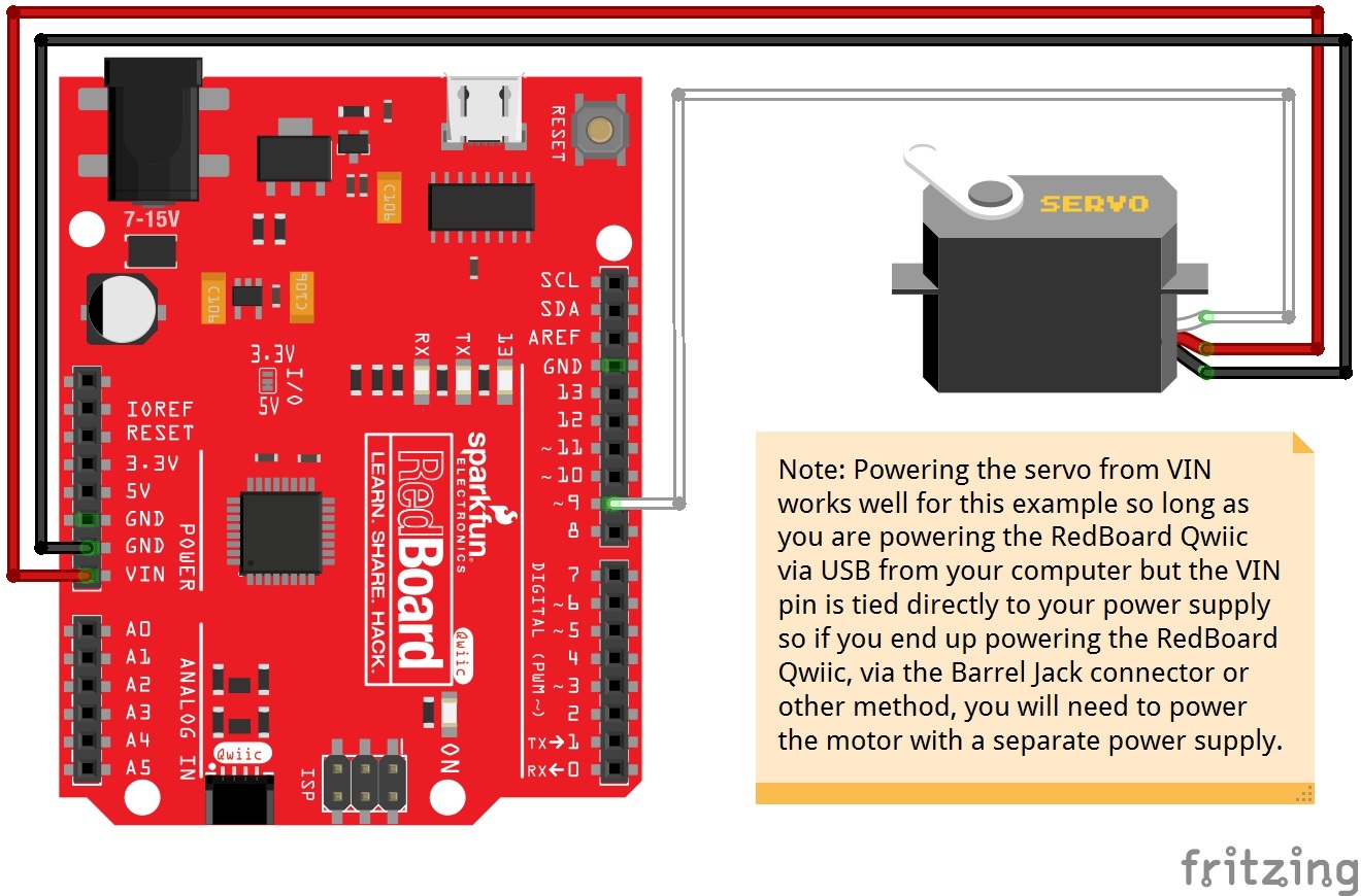
In particular, notice that power to the servo motor is supplied from the VIN pin, which bypasses the onboard regulator. The onboard regulator is insufficient to drive anything but the smallest of servos. You'll also notice that the project is powered with a 5V wall adapter. On the author's workbench, performance was marginal when the board was powered by the USB port.
Firmware
With the circuit hooked up, load the following sketch.
Note: This example assumes you are using the latest version of the Arduino IDE on your desktop. If this is your first time using Arduino, please review our tutorial on installing the Arduino IDE.
If you have not previously installed an Arduino library, please check out our installation guide.language:c
/******************************************************************************
servo-skatch.ino
Example sketch for connecting a hobby servo to a sparkfun redboard
(https://www.sparkfun.com/products/9065)
(https://www.sparkfun.com/products/12757)
Byron Jacquot@ SparkFun Electronics
May 17, 2016
**SparkFun code, firmware, and software is released under the MIT License(http://opensource.org/licenses/MIT).**
Development environment specifics:
Arduino 1.6.5
******************************************************************************/
#include <Servo.h>
Servo testservo;
uint32_t next;
void setup()
{
// the 1000 & 2000 set the pulse width
// mix & max limits, in microseconds.
// Be careful with shorter or longer pulses.
testservo.attach(9, 1000, 2000);
next = millis() + 500;
}
void loop()
{
static bool rising = true;
if(millis() > next)
{
if(rising)
{
testservo.write(180);
rising = false;
}
else
{
testservo.write(0);
rising = true;
}
// repeat again in 3 seconds.
next += 3000;
}
}
This sketch drives the servo back and forth.
Pay particular attention to the attach() call on line 26. It is using the optional min and max parameters, to constrain the pulses to the 1000 to 2000 microsecond (1 to 2 millisecond) range. As noted in the Range Constraints section above, driving a servo outside that range may damage the servo.
attach() call. With the minimum and maximum defined, the parameters to the write() method (ideally expressed in degrees) get retranslated to the constrained range. In the example, write(0) will result in a 1 millisecond pulse, and write(180) yields a 2 millisecond pulse. On an average servo, this translates to approximately 90° of motion, not the 180° that the call parameters would indicate.
The servo library also has a few other limitations. Most notably, it overrides analogWrite()on pins 9 and 10. For more information about the library, check the Arduino reference pages.
If things don't seem to be quite right, please look through the troubleshooting section.
With the Servo Trigger
Having programmed a servo example from scratch in the last section, there's another way to deploy servos that doesn't require any programming.
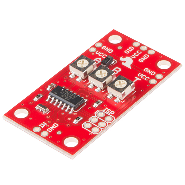
The SparkFun Servo Trigger is a small board dedicated to driving hobby servos. It has trimpots that allow you to set the servo positions and jump between the positions by actuating a switch. It is available in standard and continuous rotation versions. For more detailed information about the Servo Triggers, consult their respective hookup guides.
Troubleshooting
Regardless of how you're driving it, servos sometimes require a little extra attention to get working. Here are a few troubleshooting tips.
- Even unloaded servos can draw quite a bit of power. For full strength, you should be sure that your power supply can provide at least one Ampere per servo.
- When the power supply isn't up to the task, servos behave poorly. They'll move more slowly than a properly powered servo.
- Underpowered servos are prone to hunting, where they don't move cleanly to the desired position, but instead move back and forth near that position. They might also audibly hum, or repeatedly reset.
- In some circumstances, when the servos and processor are running off the same power supply, the servos can draw so much current (or put so much noise on the line) that it may cause your processor to reset or misbehave. The simplest solution to this issue is to run your processor and servos off separate power supplies (but be sure to have a common ground between them). More complex solutions involve power supply noise filtering techniques; Google for advice.
- Powering your project via USB is only suitable for the smallest of servo motors. A medium servo easily exceeds the 100 mA available from a USB port.
- If your power LEDs flicker when you try to actuate the servo, you're in risky territory!
- Servos have a maximum speed. If your servo is acting erratically, you may be trying to get it to switch from one position to another too quickly. Pausing between your commands gives the servo time to react.
- As mentioned in the Range Constraints section, some servos have different ranges of movement.
- When servos are driven past their end stops, they might hum, or grind their gears. Be careful if your servo starts clicking, a sign that the gears are binding.
- If this will affect your project, look for a servo that is specified to provide 180° of rotation. Also, note that the Servo library's attach() command allows you to fine-tune each servo's min and max position, to help avoid driving it beyond the limits.
Happy Servoing!
Resources & Going further
Resources
- The Servo Motor category contains a wide variety of servos. The author has found that the generic metal gear micro-size servo behaves particularly well.
- The SparkFun Servo Trigger is available in standard and continuous rotation varieties.
- The Micro Maestro is a six channel USB-to-Servo interface.
Going further
- The Wikipedia article on Radio control Servos contains more more detailed information and history of servos.
- The uArm is a robotic arm that is driven by servo motors.
- You can hack a regular servo to turn it into a continuous rotation one.
- You can also remove the control board, turning a servo into a small DC gearmotor.
For more servo fun, check out these other SparkFun tutorials: