SparkFun Blocks for Intel® Edison - PWM
 SFUptownMaker,
  CaseyTheRobot,
  HelloTechie
Introduction
SparkFun's PWM Block for the Intel Edison allows you to add eight channels of I2C controlled PWM output to your Edison stack. The headers are spaced to allow you to directly connect servo motors to the block, and an auxiliary isolated power input on the headers allows for input voltages and currents above what the rest of the Edison can use or provide.
Suggested Reading
If you are unfamiliar with Blocks, take a look at the General Guide to Sparkfun Blocks for Intel Edison.
Other tutorials that may help you on your Edison adventure include:
- Programming the Edison - This tutorial assumes you are not using the Arduino IDE, so you'll want to familiarize yourself with C++ development on the Edison.
- Powering Your Project
- Connector Basics
- PWM Basics
- LED Basics
Board Overview
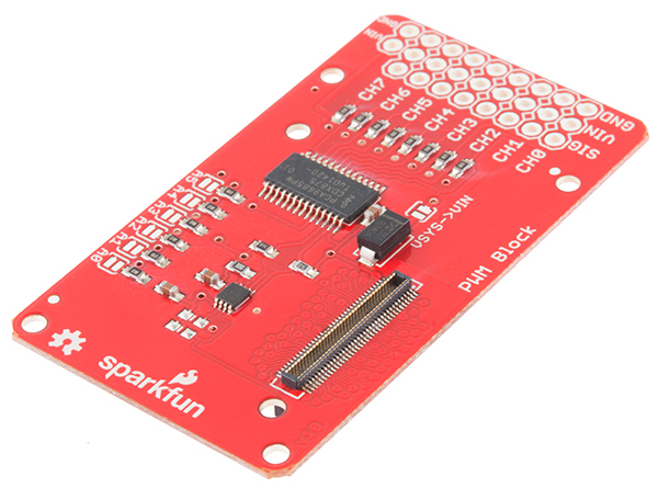
The "top" side of the board is the most interesting, so we'll look at that first.

- PWM outputs - Each PWM channel has a three-pin, 0.1" spaced header footprint. The output order is appropriate for most servo motors. All you need to do is add male header pins, and you can connect servos directly to the block. The VIN pin is, by default, floating. Before you can drive a servo, you'll need to provide power to that rail.
- Auxiliary Power Input - These pads are provided to allow you to connect an external power supply to the PWM channels. This allows you to use a higher voltage, higher current supply (for instance, a 7.2V 2S LiPo cell) to power the devices connected to the PWM outputs without risking damage to the Edison.
- VSYS->VIN jumper - If you don't need the extra oomph of an external power supply (because you're driving small LEDs or a small servo, perhaps), you can bridge this jumper with a solder blob to draw power from the Edison VSYS rail. When running from USB, you can expect that rail to be approximately 4.0V.
- Address jumpers - These jumpers allow you to set the address the PCA9685 PWM chip on this board will use. Each jumper corresponds to a single address bit; closing a jumper makes that bit a '1'. The default address is 0x40. Thus, closing A0 would make the address 0x41, A1 makes it 0x42, A0 and A1 make it 0x43, and so on.
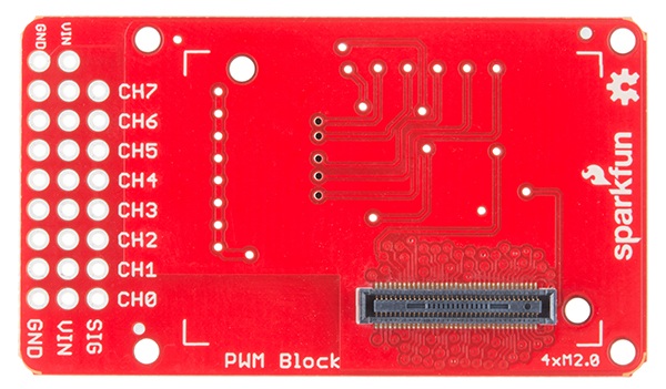
The "back" of the board is far more boring, with no jumpers or components to mention. This is the side that the Edison module will mate with, so you will be able to change jumpers without detaching the Edison.
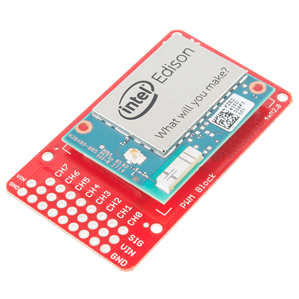
Using the PWM Block
To use the PWM Block, simply attach an Intel Edison to the back of the board, or add it to your current stack. Blocks can be stacked without hardware, but it leaves the expansion connectors unprotected from mechanical stress.
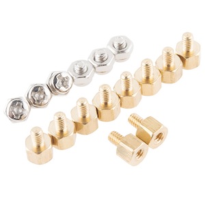
We have a nice Hardware Pack available that gives enough hardware to secure three blocks and an Edison.
NOTE: The PWM Block does not have console access or a voltage regulator. It is recommended to use a console communication block in conjunction with this block like ones found in the General Guide to SparkFun Blocks for Intel Edison.
C++ Code Examples
We're assuming that you're using the Eclipse IDE as detailed in our Beyond Arduino tutorial. If you aren't, you'll need to read that tutorial to get up to speed.
Getting Started
Follow the instructions in the programming tutorial to create a new project named "SparkFun_PWM_Edison_Block_Example". Once you've created the project, open the project files on the disk (hint: you can find the path to the project by choosing "Properites" from the project menu), and copy the source files found in the SparkFun PWM Block for Edison C++ Library directly into the "src" directory.
Hardware Connection
For this example, we've got a sub-micro servo motor and a common anode RGB LED connected to the PWM block outputs. We've closed the VSYS->VIN jumper with a solder blob, so we're drawing power from the Edison's supply. For a larger servo motor or more LEDs, you should open that jumper, and connect an external supply to the VIN and GND pads at the end of the header.

Of course, you can connect any other device to the outputs here -- the PWM input to a motor driver, a buzzer, what have you. We just want to demonstrate the core capabilities of this block, which is to provide servo driving and visually normalized LED outputs.
Code
Everything you need to know is in the comments.
/****************************************************************************
 * SparkFun_PWM_Edison_Block_Example.cpp
 * Example code showing how to use the SparkFun PWM Edison Block
 * Mike Hord @ SparkFun Electronics
 * 9 June 2015
 * https://github.com/sparkfun/SparkFun_PWM_Block_for_Edison_CPP_Library
 *
 * This file is a demonstration program showing the various functions that we've
 * provided for working with the PCA9685 IC on the SparkFun PWM Edison Block.
 * It uses an RGB LED and a small servo motor to show what the library can do.
 *
 * Resources:
 * Requires Intel's MRAA framework. This can be downloaded from either the
 * GitHub site (https://github.com/intel-iot-devkit/mraa) or in pre-built form
 * from http://iotdk.intel.com/sdk/mraa-update/.
 *
 * Development environment specifics:
 * Developed in the Intel iot-ide-dk Eclipse on Win 7 (v1.0.0.201502201135)
 * Using lib-mraa v0.6.2
 * On Edison poky-linux image build ww18-15
 *
 * This code is beerware; if you see me (or any other SparkFun employee) at the
 * local, and you've found our code helpful, please buy us a round!
 * ****************************************************************************/

#include "mraa.hpp"
#include "SparkFun_pca9685_Edison.h"
#include <iostream>
#include <unistd.h>

using namespace std;

// These channel definitions mirror the ones used in the PWM Block hookup guide.
#define SERVO 0
#define RED 2
#define GREEN 3
#define BLUE 4

// Uncomment one or both of these defines to enable the appropriate demo. Do
//  note servo motors and LEDs are best used at different frequencies and
//  polarities, so hooking both at once will give you bad results.
#define SERVO_DEMO
//#define LED_DEMO

// main() runs once and completes; there's no infinite loop here. Do note,
//  though, that whatever settings you write to the PWM module will persist
//  after the code has completed.
int main()
{
  // Variables to be used elsewhere in the program.
  uint16_t startTime, stopTime;

  mraa::I2c* pwm_i2c;   // We need to create an I2c object that we can pass to
                        //  the pca9685 constructor. If you have more than one
                        //  PCA9685 device on your bus (either by stacking more
                        //  than one PWM block or by adding external boards via
                        //  the I2C Expansion Block), you'll need to create a
                        //  different I2c object for each one!
  pwm_i2c = new mraa::I2c(1); // Tell the I2c object which bus it's on.

  pca9685 pwm(pwm_i2c, 0x40); // 0x40 is the default address for the PCA9685.

  // In general usage, you don't need to worry about getting or setting the
  //  mode registers or the prescaler register. I'm including these lines here
  //  just for example completeness purposes.
  cout<<"Current mode register values: 0x"<<hex<<pwm.readModeRegisters()<<endl;
  cout<<"Current prescaler: "<<dec<<static_cast<int16_t>(pwm.getPrescaler())<<endl;
  pwm.setPrescaler(121);

  // There are four generic functions allowing the user to change the start and
  //  stop times of the various channels. Generally, however, you shouldn't ever
  //  have to or want to use these, since there are more useful functions
  //  available which will be covered below.
  pwm.setChlTime(RED, 0, 0);
  pwm.setChlDuty(BLUE, 0);
  pwm.setChlStart(GREEN, 0);
  pwm.setChlStop(GREEN, 0);

  pwm.setChlDuty(SERVO, 0);

#ifdef LED_DEMO
  // When you call enableLEDMode(), you set the output to be approximately 400Hz
  //  and inverted. Thus, a 0 output will be a 100% high output. This allows us
  //  to use the output to drive common anode LEDs. See the tutorial for an
  //  example circuit.
  pwm.enableLEDMode();
  // Back to this, just so you can compare the settings in LED mode with the
  //  default (which is actually LED mode).
  cout<<"Current mode register values: "<<hex<<pwm.readModeRegisters()<<endl;
  cout<<"Current prescaler: "<<dec<<static_cast<int16_t>(pwm.getPrescaler())<<endl;
  for (uint8_t i = 0; i <= 100; i++)
  {
    // Check and print the start and stop times for the RED channel, then set
    //  all three to one percentage point higher. You'll note that the start
    //  time is always 0, and that the stop times increase logarithmically. This
    //  lets us get a visually linear brightness out of the LEDs.
    pwm.getChlTime(RED, &startTime, &stopTime);
    cout<<"Start time: "<<dec<<startTime<<endl;
    cout<<"Stop time: "<<dec<<stopTime<<endl;
    pwm.setChlLEDPercent(BLUE, i);
    pwm.setChlLEDPercent(GREEN, i);
    pwm.setChlLEDPercent(RED, i);
    usleep(100000);
  }
  sleep(4);
  pwm.setChlTime(RED, 0, 0);
  pwm.setChlTime(GREEN, 0, 0);
  pwm.setChlTime(BLUE, 0, 0);
  cout<<"LED demo complete!"<<endl;
#endif

#ifdef SERVO_DEMO
  // We can set or get the minimum and maximum angles the angle set function
  //  expects to see.
  int16_t servoMinAngle, servoMaxAngle;
  pwm.getServoAngleLimits(&servoMinAngle, &servoMaxAngle);
  cout<<"Current servo min angle: "<<dec<<servoMinAngle<<endl;
  cout<<"Current servo max angle: "<<dec<<servoMaxAngle<<endl;

  // Likewise, we can set the min and max of pulse widths. Each count here is
  //  about 4.5us, depending on the clock's accuracy.
  uint16_t minServoPL, maxServoPL;
  pwm.getServoAnglePulseLimits(&minServoPL, &maxServoPL);
  cout<<"Current servo min pulse length: "<<dec<<minServoPL<<endl;
  cout<<"Current servo max pulse length: "<<dec<<maxServoPL<<endl;

  // These numbers are based on experimentation with SparkFun's generic
  //  sub-micro servo motor. You may find that they are too high or too low for
  //  your particular motor. The generic settings are fairly conservative and
  //  there is no need to use these functions unless you feel like you can get
  //  a wider range of motion by doing so.
  servoMinAngle = 0;
  servoMaxAngle = 160;
  minServoPL = 108;
  maxServoPL = 450;
  pwm.setServoAnglePulseLimits(minServoPL, maxServoPL);
  pwm.setServoAngleLimits(servoMinAngle, servoMaxAngle);

  // enabling servo mode makes the output active high and sets the frequency to
  //  approximately 50Hz.
  pwm.enableServoMode();

  // For comparison against default values or LED mode values.
  cout<<"Current mode register values: 0x"<<hex<<pwm.readModeRegisters()<<endl;
  cout<<"Current prescaler: "<<dec<<static_cast<int16_t>(pwm.getPrescaler())<<endl;

  // This steps through the full range of your servo's rotation. It also shows
  //  the start and stop time of the pulses, so you can see how those correspond
  //  to different positions.
  for (int16_t i = servoMinAngle; i <= servoMaxAngle; i++)
  {
    pwm.getChlTime(SERVO, &startTime, &stopTime);
    pwm.setChlAngle(SERVO, i);
    cout<<"Start time: "<<dec<<startTime<<endl;
    cout<<"Stop time: "<<dec<<stopTime<<endl;
    usleep(100000);
  }
  cout<<"Servo demo complete!"<<endl;
#endif

  return MRAA_SUCCESS;
}
Resources and Going Further
Now that you have had a brief overview of the PWM Block, take a look at some of these other tutorials. These tutorials cover programming, Block stacking, and interfacing with the Intel Edison ecosystems.
Edison General Topics:
- General Guide to Sparkfun Blocks for Intel Edison
- Edison Getting Started Guide
- Loading Debian (Ubilinix) on the Edison
Block Specific Topics:
Check out these other Edison related tutorials from SparkFun: