Continuous Rotation Servo Trigger Hookup Guide
 Byron J.
 Introduction
When we introduced the regular Servo Trigger, we mentioned that it could be reprogrammed to be more useful with continuous rotation servo motors. However, reprogramming the firmware is somewhat tedious, and users asked for a Servo Trigger preprogrammed with the continuous rotation logic. You asked, and we listened! Introducing the Continuous Rotation Servo Trigger! The name is a mouthful, but if you're looking for an easy way to deploy continuous rotation servos, it should be exactly what you're looking for.
Like its sibling, the Continuous Rotation Servo Trigger allows you to control a hobby servo motor without any programming. The servo speed and direction are adjusted using trimpots, and the direction can be changed by attaching a switch.
In this guide, we'll show you how to quickly get your CR Servo Trigger working, then discuss some of the finer details of using and configuring it. Finally, we'll show how it was used to build a simple automated camera dolly.
Suggested Reading
- We're not going to get too deep into the basics of hobby servos in this hookup guide. If you want more detailed information, check out our Hobby Servo Tutorial.
- Some more background on motors.
- If you came here looking for information about the regular Servo Trigger, you can find its hookup guide over here.
Continuous Rotation Servo Motors
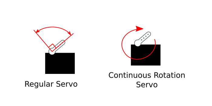
A continuous rotation servo (sometimes called a full rotation or 360° servo) looks like a regular hobby servo. While a regular servo motor only turns over a narrow range, with precise control over position, a continuous rotation servo has a shaft that spins continuously, with control over its speed and direction.
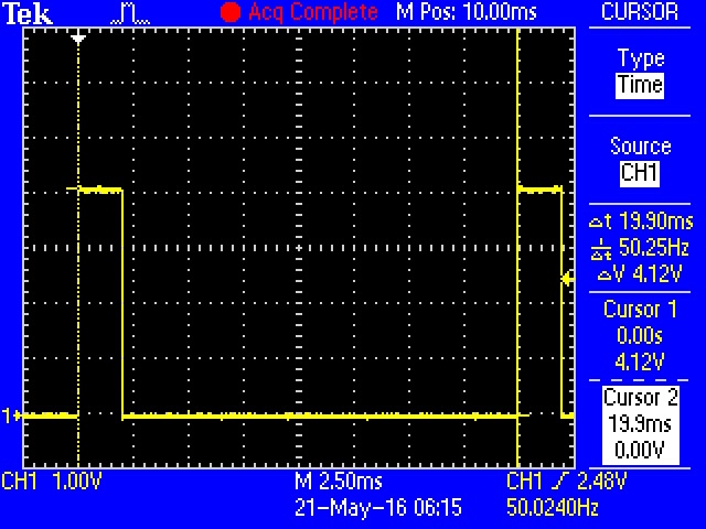
The control is performed using a pulse train signal, typically with pulses that vary from 1 to 2 milliseconds, sent every 20 milliseconds (50 Hz). A one millisecond pulse corresponds to full speed in one direction, while a two millisecond pulse is full speed in the other direction. These pulses are easy to generate using the pulse-width-modulation hardware on a modest microcontroller.
Halfway between those extremes, a 1.5 millisecond pulse should cause the motor to stop. Most CR servos have an adjustment screw or trimpot that allows you to fine tune the point at which it stops, a calibration procedure often called nulling.
With the CR Servo Trigger, the stop point can be adjusted on the board, but if it behaves unexpectedly, double check that the trim on the servo itself isn't the root of the problem.
Getting Started Quickly
Let's jump in and build a circuit to show how the Servo Trigger works!
Materials and Tools
You'll need to following materials to build this example circuit found in this tutorial.


You'll also need some hookup wire and a small screwdriver.
Doublecheck The Trigger
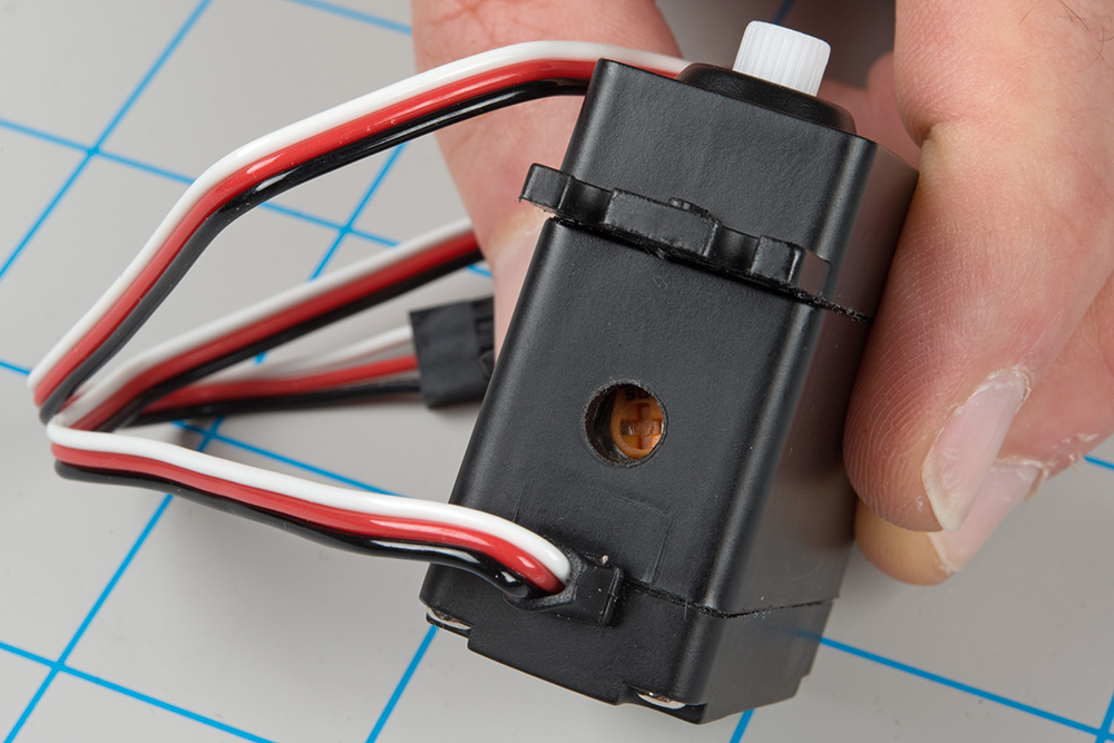
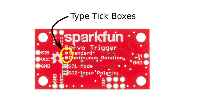
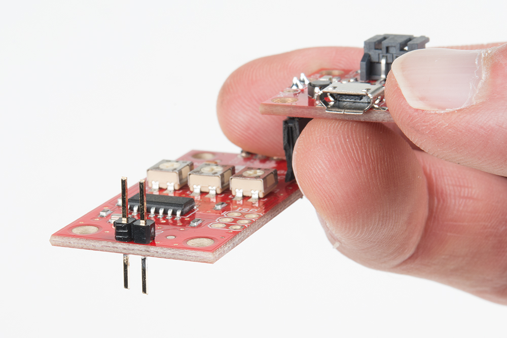
Before we start building, doublecheck that you've got a Continuous Rotation Servo Trigger. There are tick boxes on the back of the PCB, and the "continuous rotation" box should be marked.
Preparations
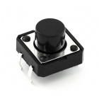
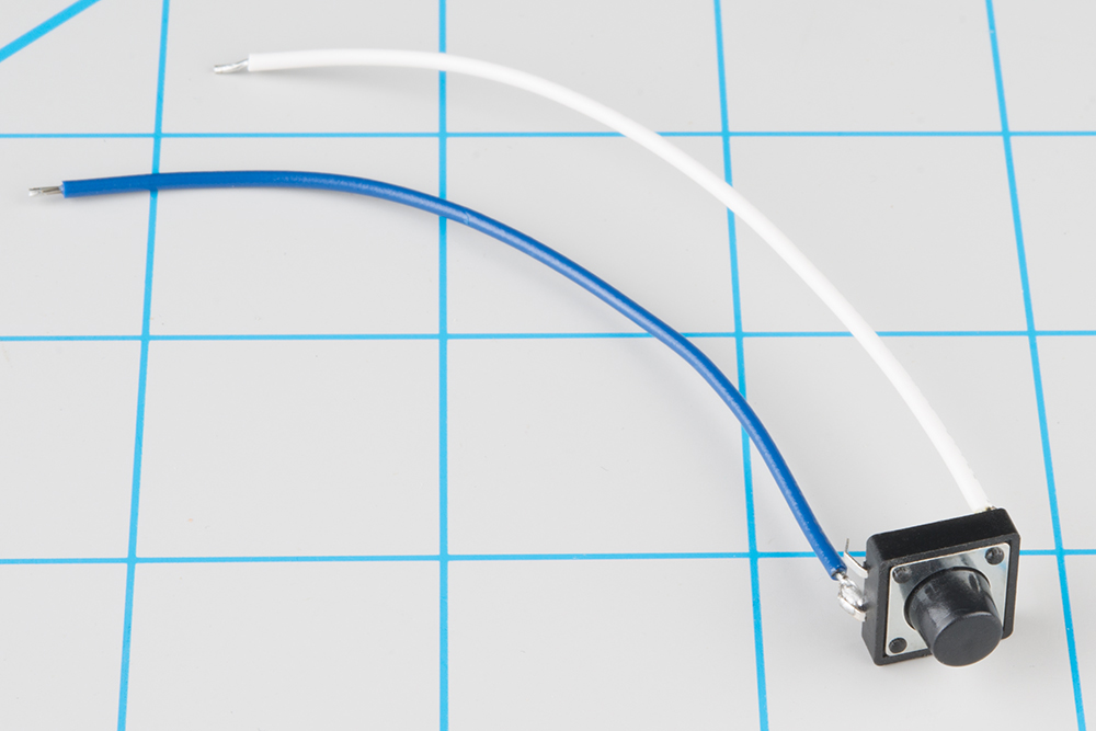
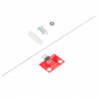
To start, solder some wires to the tactile switch. If you solder to legs on on opposite corners (top-right and lower-left, for instance), you can be confident that you'll get a contact closure when you press the button.
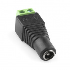
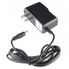
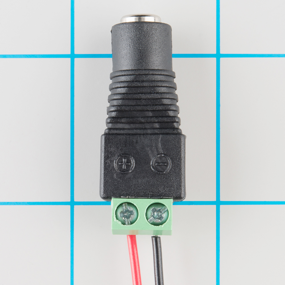
Next, prepare the power plug pigtail. Take a pair of wires, and strip the ends. Then screw them to the power jack adapter -- if you look closely at the adaptor, you'll notice that there are a small + and - embossed in the plastic. We used a red wire for VCC on the + terminal and a black wire for ground on the - terminal.
Take your right-angle male headers, and snap of a section of three headers. Solder the 3-pin header to the three pads on the end the board, and plug the servo into the the header. Be careful to get the plug oriented correctly -- you can check the color code table in the servo tutorial, or consult the servo manufacturer's datasheet.
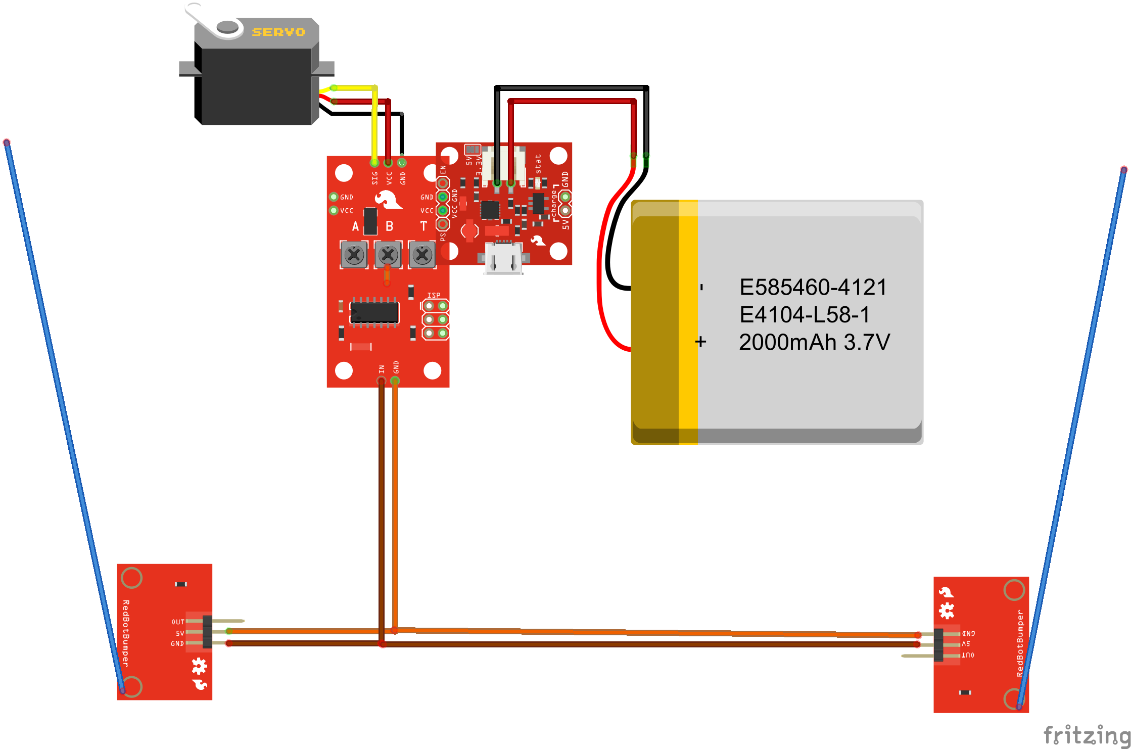
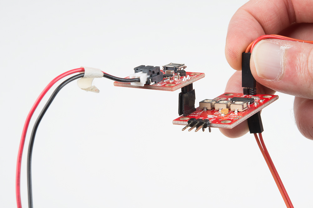
Solder the switch wires to the IN and GND pads on the Servo Trigger and the power pigtail to the VCC and GND pads on the edge of the board. These are mirrored on opposite edges of the board -- they're wired in parallel, so you can use either set of pads. The red wire should connect to the VCC pad and the black to GND.
Before we power up, take a moment to double-check your work against the photo below (click on the picture for a larger version). In particular, make sure that the power and servo connections are oriented correctly.
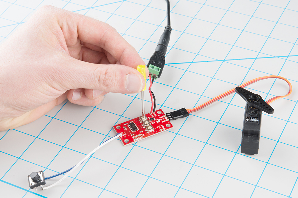
Adjust the trimpots on the back of the board. Set A fully counterclockwise, B fully clockwise, and set T to the middle.
Finally, apply power. The servo should start to turn. If not, power down, and recheck your work.
While it's running, tap the switch. The servo will take a couple of seconds to slow down, stop, then reverse. Tap the switch again, and it will go back to the original direction.
Now you can adjust the trimpots to configure the servo.
Asets the speed and direction of the motor before the switch is actuated.Bsets the speed and direction of the motor after the switch is actuated.Tsets the time it takes to get from A to B and back.
When A and B are near the middle of their rotation, the servo will stop. Turning them clockwise from there instructs the servo to turn in one direction; turning them counterclockwise results in the opposite direction. The farther from the center, the faster the servo turns. The transition time is adjustable between 50 milliseconds and 10 seconds. The transition time is constant -- when set to 2 seconds, the servo will take 2 seconds to move between A and B, regardless of how close the A and B settings are.
In the next section, we'll explore some of the finer details of the Continuous Rotation Servo Trigger.
Theory Of Operations
The Servo Trigger consists of two major engineering deliverables, the hardware design, and the firmware. The hardware is actually the same for the regular and continuous rotation boards, but they're loaded with different firmware, tailoring the board's behavior to each type of servo motor. Both sets of deliverables are in the Servo Trigger Github repository.
On The Board
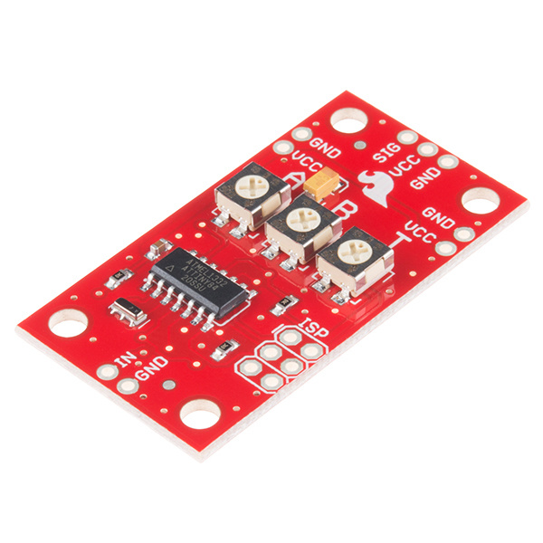
Let's look at the components on the board and examine what they do.
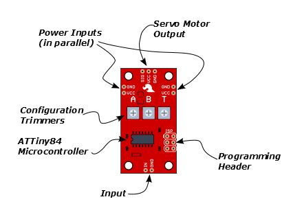
The heart of the Servo Trigger is an Atmel ATTiny84 microcontroller, running a small program that implements the servo control features we are discussing here. Just because the Servo Trigger saves you from needing to write code doesn't mean that there was no programming involved!
The servo control signal is generated using a 16-bit hardware timer. It runs off a 1 MHz clock, counting to 20000 to generate the 20 mSec (50 Hz) period and is configured to generate pulses that range from 1000 to 2000 µSec (1 to 2 milliseconds).
The three potentiometers are connected as voltage dividers between VCC and ground. They are read using analog inputs ADC0, ADC3, and ADC7.
The switch input is read using PortA, input pin 1. It is debounced in software and can be configured to watch for a switch closure or a logic level pulse.
The board also includes the common 6-pin in-system-programming header, which we'll discuss in the Servo Trigger Programming Guide. But we're getting a bit ahead of ourselves -- there are some configuration options you can use without programming.
Configuration
The Servo Trigger has a couple of configuration options. If you look at the back of the PCB, you'll notice two solder jumpers that can be used to change Servo Trigger's response.
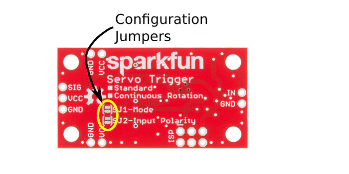
When it first powers up, the servo trigger reads these jumpers and configures itself accordingly.
Modes
The Servo Trigger has two different servo control modes, selected with solder jumper 1 (SJ1). They can be used to tailor the response of the board for different applications.
The default mode implements toggling control. The trigger initializes driving the servo as instructed by trimmer A. When the switch closes, it transitions to the speed indicated by B. When the switch closes again, it returns to A. The time taken to get between A and B is selected using trimmer T, which ranges from nearly instantaneous to 10 seconds, allowwing the motor to gradually slow, stop, and reverse.

This behavior can be changed by flowing solder between the pads of the mode jumper.

With the solder jumper closed, the mode changes to bistable control -- the servo will drive at speed A while the switch is open, and speed B while the switch is closed. While the switch input stays in a state, the servo drives at the corresponding speed -- it is stable in two different states.

Input Polarity
The Servo Trigger input sensitivity can also be changed, using solder jumper 2 (SJ2).
The default configuration, with no solder applied, configures the Servo Trigger for use with a normally-open switch, with the internal pull-up resistor on the microcontroller enabled. This configuration is also suitable for use with an active-low logic input.
With SJ2 closed, the internal pull-up is disabled, and the input is set as an active-high logic input.
A note about nomenclature: since the input polarity can be swapped, it can be hard to talk about -- the voltage might be high, but when the sense is inverted, it indicates that the input isn't being actuated. To help navigate this, the polarity-neutral terms active or asserted are used to describe when the input is being used, and inactive or deasserted to describe the default state.
More components
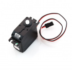
The servo trigger can be used with a wider variety of external components than used in the example above. We used a standard size continuous rotation servo, though we also offer a micro size one.
You can also use different switches, such as micro switches or foot pedals.
Power Notes
Compared to a servo motor, the Servo Trigger board draws very little current -- roughly 5 mA.
The motor draws significantly more -- a quick bench test using a small servo, with only a lightwieght horn attached, shows the motor draws 10 mA sitting idle, and about 70 mA while moving. Grabbing the horn and twisting causes the controller to apply current to the motor, counteracting the twist. It drew 700 mA during this test -- a larger servo could draw even more!
These currents can get surprisingly high as you add more motors to the system -- you'll need to select a power supply with adequate capacity. An Ampere per motor is a reasonable guideline. For more information about powering servos, please see the powering a servo section of our Servo Tutorial.
When in doubt, grab a multimeter, measure the current consumed, and check whether VCC at the board input is falling below the expected voltage when the servos are turning.
Troubleshooting
If there's no change when you actuate the input, first check that A and B are not set to the same position, otherwise there's no speed change!
If you're feeding the input with a logic signal from an external device, be sure to drive the signal for more than 50 milliseconds. The PWM signal is updated every 50 mSec, and events shorter than that may be missed.
If the servo only turns on one direction, doublecheck that the trimpot on the servo is near the center of its range. If it's near one end or the other, the servo will go from full speed to stopped, but not reverse.
For additional servo troubleshooting ideas, please consult the Servo Turorial.
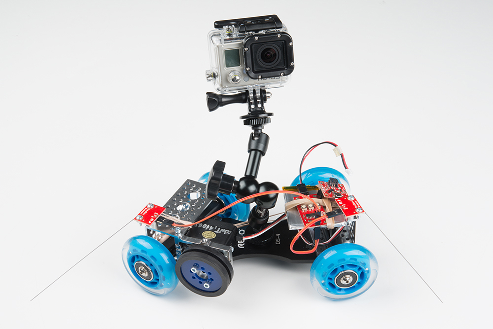
Example Project
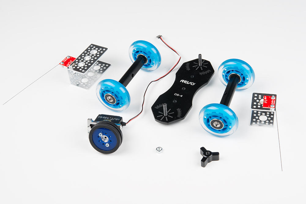
To demonstrate the usefulness of the Continuous Rotation Servo Trigger, we put a continuous rotation servo on a small camera dolly. The dolly has a whisker switch at each end, allowing it to do automated tabletop camera moves.
Lacking an old-fashioned rollerskate to dismantle for the chassis, we started with a commercial camera skate dolly.

We also had some derelict robot parts around the workshop that we used to hold everything together. We improvised using materials we had handy and suggest that you do the same!
Build the Circuit
To start, we assembled the circuit on the workbench.
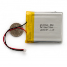
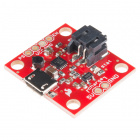
We used male and female headers to stack the Power Cell atop the Servo Trigger board.
The whisker switches were assembled as described in this hookup guide, with one built in right-hand orientation and the other left-handed.
The whisker switches also needed a quick electronic modification to make them compatible with the Servo Trigger. We desoldered the resistor from the PCB and replaced it with a blob of solder, so the whisker acts as a simple switch closure.

We plugged the 2 pin jumper wires into the GND and 5V pins on the switches and stuck some long pin headers through the switch contacts on the trigger PCB, so the switches could both plug in in parallel, one from above, the other from beneath.
We gave it a quick test on the bench. Each time a whicker switch closed, the motor drove the other way. The A, B, and T adjustments each had the desired effect.
Mechanical Integration
With the electronics working, we put them on the chassis.
The chassis itself consists of a platform with a couple of protruding M6 machine screws. The axles are mounted to the screws with wingnuts.
The drive mechanism for the cart is a simple slip clutch. We fashioned a double-width rubber wheel onto the servo using Actobotics 2" wheels and a pair of servo hubs. The motor was mounted to a B-type servo bracket, which was connected to the end of a 4.5" channel. The bracket was free to pivot in the end of the channel.
The bracket channel was simply placed over the axle bolt on the cart chassis. A rubber band was looped around the assembly, putting tension on the servo, so that the drive wheel gently touched one of the skate wheels.
On the other end of the cart, a 1.5" channel was placed over the other pivot. This allowed both axles on the cart to be spaced evenly, ensuring that all four skate wheels touch the tabletop. It also gave us some holes to mount the front whisker switch and a place to secure the battery and other electronics.
Testing Results
The first time out was somewhat disappointing -- the cart would drive until the first switch closed, then stall. It turns out the battery was nearly discharged! After a couple hours charging from a USB port, it behaved as expected.
We adjusted the trimmers so it drove slowly in both directions, with a medium transition time, so it wouldn't skid or jerk as it turned around.
Resources and Going Further
Resources
- For more background information on servo motors, check out the Hobby Servo Tutorial.
- We've got continuous rotation servos in both micro and standard sizes.
- The design files for the Servo Trigger PCB and firmware can be found in the Servo trigger Github Repository
Going Further
- If you're ambitious, you can program the Servo Trigger with your own custom firmware. Consult the Servo Trigger Programming Guide for details.
- If you're looking to control standard hobby servos, we also offer the Standard Servo Trigger, and a wide variety of standard servo motors.