Servo Trigger Hookup Guide
 Byron J.
Introduction
The Servo Trigger is a small board that helps you deploy hobby RC servo motors. When an external switch or logic signal changes state, the Servo Trigger tells an attached servo motor to move from position A to position B.
To use the Servo Trigger, you simply connect a hobby servo and a switch, then use the onboard potentiometers to adjust the start/stop positions and transition time. You can use a hobby servos in your projects without having to do any programming!
In This Tutorial
This hookup guide starts with some background information about hobby servo motors. From there, it jumps into getting the Servo Trigger working with a small servo, then examines some of the inner workings. Finally, for the adventurous, it explains how to customize the Servo Trigger by reprogramming it.
Suggested Reading
- An Introduction to Motors.
- More information about hobby servo motors.
- Some background on Pulse Width Modulation.
Servo Motor Background
In the most generic sense, a "servomechanism" (servo for short) is a device that uses feedback to achieve the desired result. Feedback control is used in many different disciplines, controlling parameters such as speed, position, and temperature.
In the context we are discussing here, we are talking about hobby or radio-control servo motors. These are small motors primarily used for steering radio-controlled vehicles. Because the position is easily controllable, they are also useful for robotics and animatronics. However, they shouldn't be confused with other types of servo motors, such as the large ones used in industrial machinery.
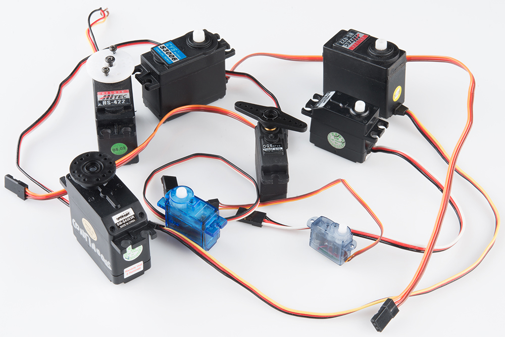
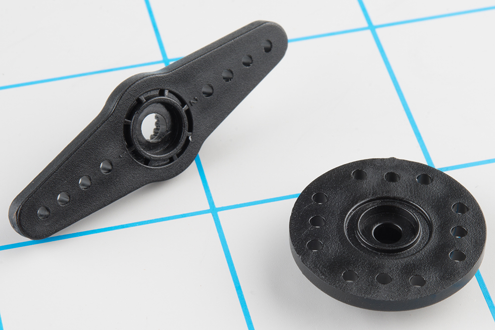
RC servos are reasonably standardized - they are all a similar shape, with mounting flanges at each end, available in graduated sizes. Servos often come with several wheels or levers, known as "horns", than can be attached to the shaft, to fit the device they are operating.
Electrical Connection
Most hobby servos use a standard type of 3-pin plug, with the same control signaling, which makes RC servos reasonably interchangeable.
The connector is a 3-pin, 0.1" pitch header. One thing that can be confusing is that the wiring color code isn't always consistent -- there are several color codes at play. The good news is that the pins are usually in the same order, just that the colors on them are different.
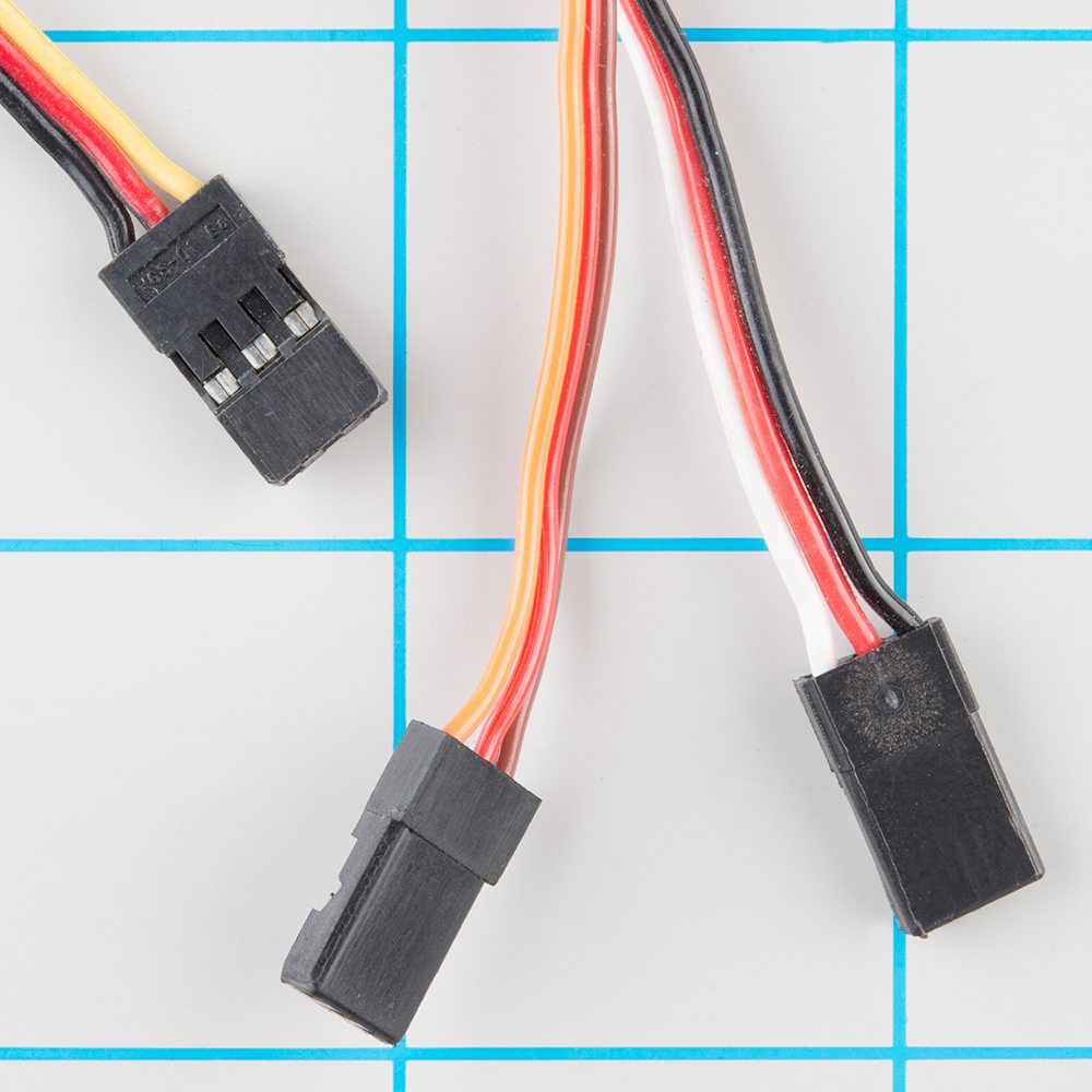
The table below summarizes common color schemes.
| Pin Number | Signal Name | Color Scheme 1 (Hitec) |
Color Scheme 2 (JR) |
Color Scheme 3 (Futaba) |
|
| 1 | Ground | Black | Brown | Black | |
| 2 | Power Supply | Red | Brown | Red | Red |
| 3 | Control Signal | Yellow | White | Orange | White |
Powering Servos
In RC vehicles, 5.5V is the nominal battery voltage. It will be somewhat higher after a charge, and it will droop as the batteries discharge. As the voltage drops, the available torque also drops -- if you've driven RC vehicles, you're no doubt familiar with the loss of control that occurs as the batteries get weaker. It starts to feel sluggish just before it dies.
If you're not using batteries, the 5VDC available from a garden variety power supply is a good option. If you're using the Servo Trigger to control your motor, the absolute maximum supply voltage that should be applied is 5.5 VDC.
Regardless of how you're powering them, it's worth noting that the current consumed by the motor increases as the mechanical loading increases. A small servo with nothing attached to the shaft might draw 10 mA, while a large one turning a heavy lever might draw an Ampere or more!
Control signal
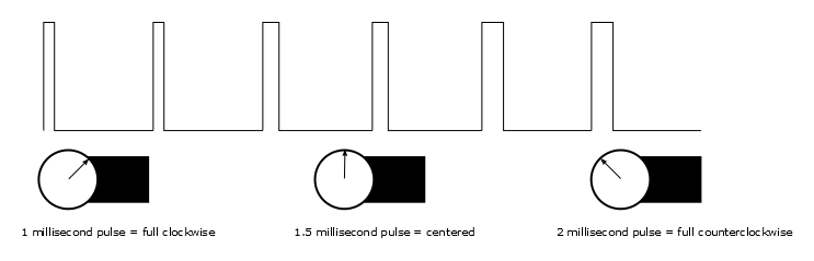
Servos are controlled with a specific type of pulse train signal. The pulses occur at a 20 mSec (50 Hz) interval, and vary between 1 and 2 mSec in width. The Pulse Width Modulation hardware available on a microcontroller is a great way to generate servo control signals.
Common servos rotate over a range of 90° as the pulses vary between 1 and 2 mSec -- they should be at the center of their mechanical range when the pulse is 1.5 mSec.
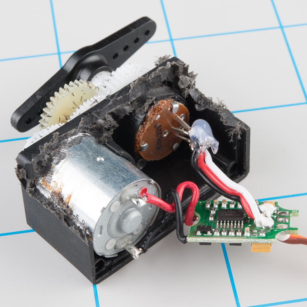
Internally, the mechanism of a servo motor uses a potentiometer attached to the rotating shaft to sense the position. It measures the width of the incoming pulse, and applies current to the motor to turn the shaft correspondingly.
Here are the insides of a servo that's been dissected. You can see the DC motor, position potentiometer, and a small PCB. The PCB has a chip on one side, possibly a small microcontroller.
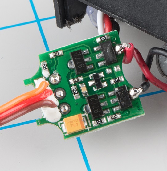
The other side of the PCB has some discrete transistors, probably in an H-bridge configuration, which allow the controller to steer current through the motor in either direction, for both clockwise and counterclockwise rotation.
One Other Useful Servo
Ordinary RC servos turn over a 90° range -- it's useful for turning a steering linkage, or adjusting the control surfaces on an airplane, but not so useful as a drive mechanism. That's where full or continuous rotation servos come in.
Rather than controlling position, the continuous rotation servo translates the same pulse-train signal into the rotational speed and direction of the shaft. Otherwise, they're very similar to regular RC servos -- they use the same power supply, control signals, 3-pin connector, and are available in the same sizes as RC servos.
The overall speed is relatively low -- around 60 RPM is a common maximum rate -- if you need higher rotation speed, servos aren't the best fit -- DC gearmotors or brushless DC motors are more likely candidates, but they aren't directly compatible with servo control signals.
With the Servo Trigger
The Servo Trigger is capable of controlling both regular and continuous rotation servos. We'll explore some more specific use cases in the following sections.
Getting Started Quickly
Let's jump in and build a circuit to show how the Servo Trigger works!
Materials and Tools
You'll need to following materials to build this example circuit.
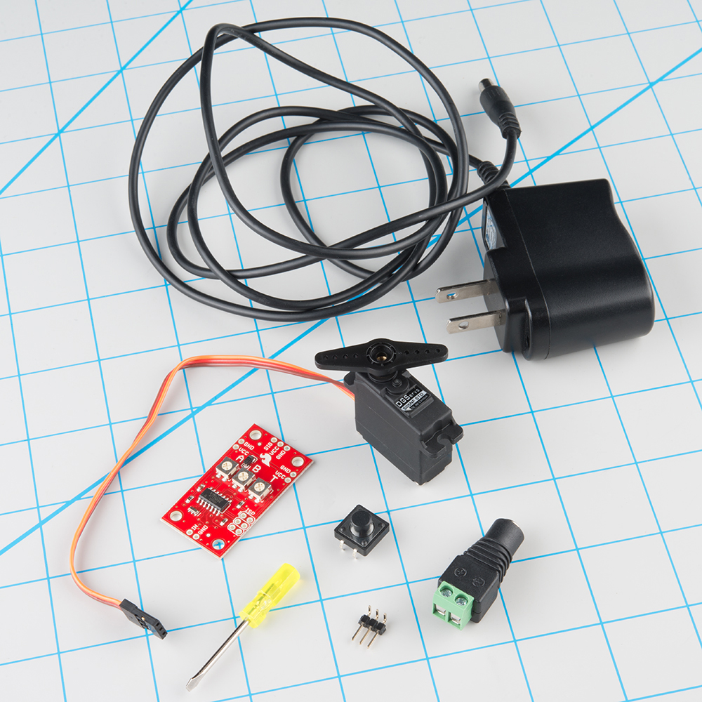
- The Servo Trigger module.
- A hobby servo motor - we'll be using our micro size metal gear servo.
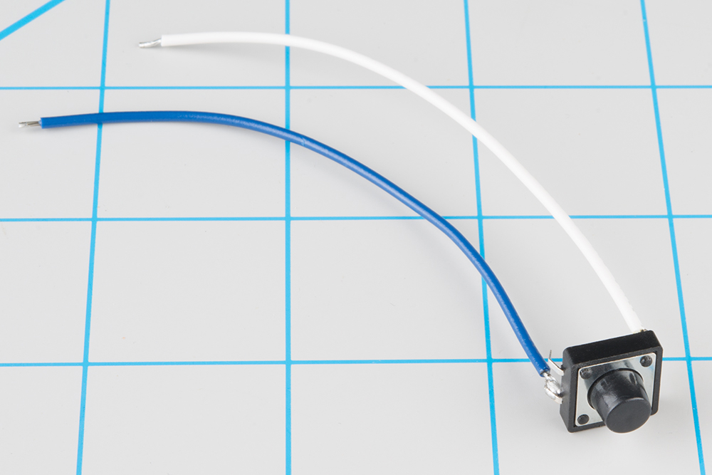
- A switch - any momentary-contact switch is suitable, so we'll use a 12mm tactile pushbutton.
- A 5V power supply.
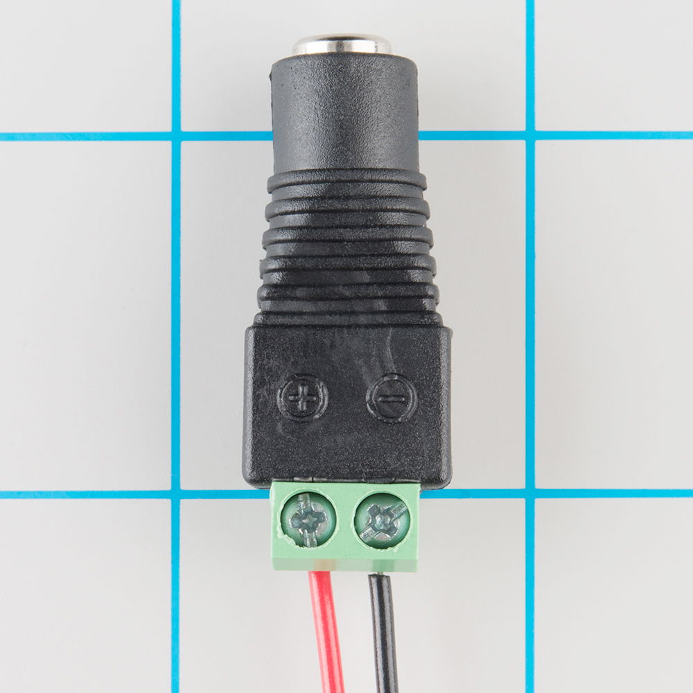
- A barrel jack adapter to make conecting the power supply easier.
- A 3-pin section of a snappable header, either straight or right-angle.
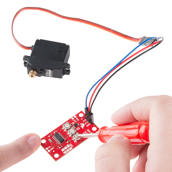
- A small screwdriver to adjust the trimpots.
- Finally, not shown, we'll need some hookup wire and soldering tools.
Hardware Hookup
You will need to make the following connection. Below is a Fritzing diagram of the parts connected to the Servo Trigger. We'll go through step by step in the next section showing how to connect the components together.
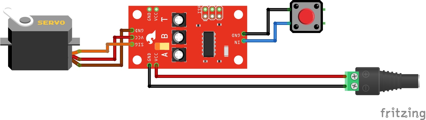
Beginning Steps
To start, solder some wires to the tactile switch. If you solder to legs on on opposite corners (top-right and lower-left, for instance), you can be confident that you'll get a contact closure when you press the button.
Then prepare the power plug pigtail. Take a pair of wires, and strip the ends, then screw them to the power jack adapter -- if you look closely at the adaptor, you'll notice that there are a small + and - embossed in the plastic. We used a red wire for VCC on the + terminal, and a black wire for ground on the - terminal.
Next, solder the 3-pin header to the 3 pads on the end the board, and plug the servo into the the header. Be careful to get the plug oriented correctly -- you can check the color code table in the previous section, or consult the servo manufacturer's datasheet.
Then solder the switch wires to the IN and GND pads on the Servo Trigger, and the power pigtail to the VCC and GND pads on the edge of the board. These are mirrored on opposite edges of the board -- they're wired in parallel, so you can use either set of pads. The red wire should connect to the VCC pad, and the black to GND.
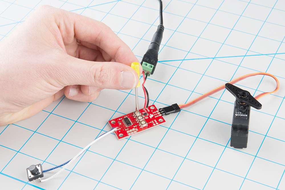
Before we power up, take a moment to double-check your work against the photo below (click on the picture for a larger version). In particular, make sure that the power and servo connections are oriented correctly.
Adjust the trimpots on the back of the board. Set A fully counterclockwise, B fully clockwise, and set T to the middle.
Finally, apply power. The servo will probably jump to a new position as you do this.
Then, press and hold the switch. The servo will rotate, taking a couple of seconds to reach its new position. Release the switch, and it will go back to the starting point.
Now you can adjust the trimpots to configure the servo.
Asets the position the servo sits in while the switch is open.Bsets the position the servo moves to when the switch is closedTsets the time it takes to get from A to B and back.
Turning the position pots clockwise will make the motor turn further clockwise. If A is higher than B, then the servo will turn counterclockwise when the switch is actuated. The timing range is adjustable between 50 milliseconds and 3 seconds. The transit time is constant -- when set to 2 seconds, the servo will take 2 seconds to move between A and B, regardless of how close the position settings are.
In the next section, we'll explore some of the finer details of the Servo Trigger.
More Details
On The Board
Let's look at the components on the board and examine how it works.
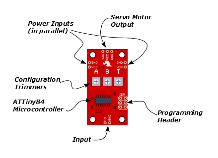
The heart of the Servo Trigger is an Atmel ATTiny84 microcontroller, running a small program that implements the servo control features we are discussing here. Just because the Servo Trigger saves you from needing to write code doesn't mean that there's no programming involved!
The servo control signal is generated using a 16-bit hardware timer. It runs off a 1 MHz clock, counting to 20000 to generate the 20 mSec (50 Hz) period and configured to generate pulses that range from 1000 to 2000 µSec (1 to 2 milliseconds).
The three potentiometers are connected as voltage dividers between VCC and ground. They are read using analog inputs ADC0, ADC3, and ADC7.
The switch input is read using PortA, input pin 1. It is debounced in software and can be configured to watch for a switch closure, or a logic level pulse.
If you're interested, you can download the schematic, PCB layout and firmware files from the Servo Trigger GitHub Repository. The board also includes the common 6-pin in-system-programming header, which we'll discuss in the Expert Exercises section. But we're getting a bit ahead of ourselves -- there are configuration options you can use without programming.
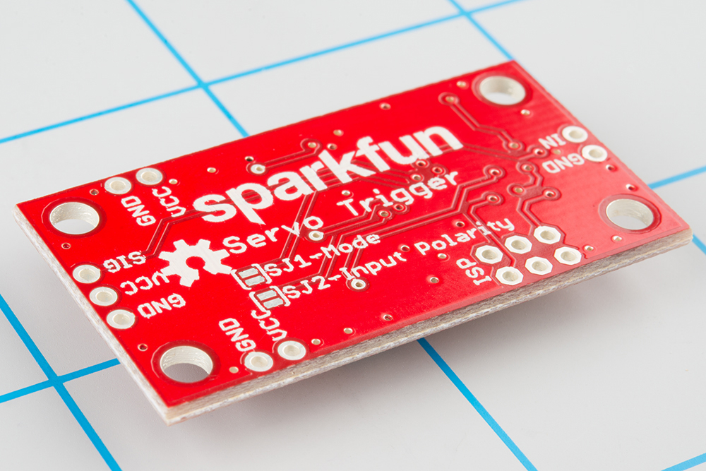
Configuration
The Servo Trigger has a couple of configuration options. If you look at the back of the PCB, you'll notice two solder jumpers that can be used to change Servo Trigger's response.
When it first powers up, the servo trigger reads these jumpers, and configures itself accordingly.
Modes
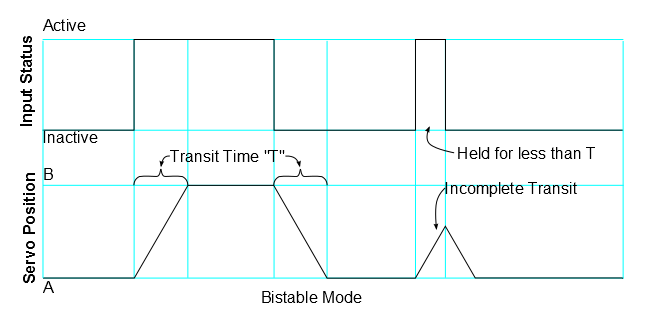
The Servo Trigger has two different servo control modes, selected with solder jumper 1 (SJ1). They can be used to tailor the response of the board for different applications.
The default mode implements bistable control -- the servo will sit at position A or position B, depending on the input actuation. While the switch stays in a state, the servo stays in the corresponding position -- it is stable in two different states.
This behavior can be changed by flowing solder between the pads of the jumper.
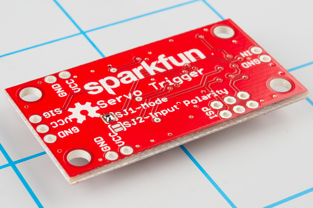
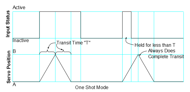
With the solder jumper closed, the mode changes to one-shot or monostable. When the input is actuated, the servo will move from A to B, then back to A -- the servo is stable in the A position, and only passes through the B position momentarily. Regardless of when the input is cleared, the servo will make a complete transit.
Input Polarity
The Servo Trigger input sensitivity can also be changed, using solder jumper 2 (SJ2).
The default configuration, with no solder applied, configures the Servo Trigger for use with a normally-open switch, with the internal pull-up resistor on the microcontroller enabled. This configuration is also suitable for use with an active-low logic input.
With SJ2 closed, the internal pull-up is disabled, and the input is set as an active-high logic input.
If SJ2 is closed, be careful about powering up the Servo Trigger when the input is not connected to anything. When the input is floating, it can randomly toggle between active and inactive and may cause the motor to behave unpredictably.
A note about nomenclature here: since the input polarity can be swapped, it can be hard to talk about -- the voltage might be high, but when the sense is inverted, it indicates that the input isn't being actuated. To help navigate this, the polarity-neutral terms active or asserted are used to describe when the input is being used, and inactive or deasserted to describe the default state.
More components
The servo trigger can be used with a wider variety of external components than used in the example above. We used a mid-sized servo, though we have many other candidates, in a wide variety of sizes & torque ratings.
You can also use different switches, such as micro switches and foot pedal switches.
Power Notes
Compared to a servo motor, the Servo Trigger board draws very little current -- roughly 5 mA.
The motors draw significantly more -- a quick bench test using a small servo, with only a lightwieght horn attached, shows the motor draws 10 mA sitting idle, and about 70 mA while moving. Grabbing the horn and twisting causes the controller to apply current to the motor, counteracting the twist. It drew 700 mA during this test -- a larger servo could draw even more!
These currents can get surprisingly high as you add more motors to the system -- you'll need to select a power supply with adequate capacity.
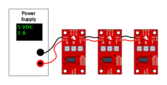
The Servo Trigger is designed to make it easy to daisy chain boards -- you can simply connect the VCC and GND pads on adjacent boards.
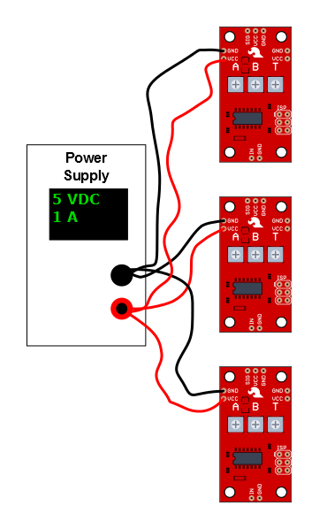
In applications where the motors are moving non-trivial loads, it's a better bet to use heavier gauge wires and give each Servo Trigger a direct connection to the power supply. The configuration is commonly known as "star power."
When in doubt, grab a multimeter, measure the current consumed, and check whether VCC at the board input is falling below the rated voltage when the servos are turning.
Troubleshooting
If there's no motion when you actuate the input, first check that A and B are not set the same, otherwise there's no position change!
If you're feeding the input with a logic signal from an external device, be sure to drive the signal for more than 50 milliseconds. The PWM signal is updated every 50 mSec, and events shorter than that may missed.
It's also possible to set T shorter than the time it take the servo motor to physically rotate. In this case, the motor may not reach B before returning to A. Try turning up T, to see if a longer transition time allows the motor to turn.
Expert Exercises
Customizing the Servo Trigger
The Servo Trigger was designed to make using servo motors easy, but it may not fit every application. You might need different timing, or different logic that interprets how the input is translated into the motor drive signal.
Since the heart of the Servo Trigger is a microcontroller, the firmware on that controller can be reprogrammed. And because the design is released as Open Source Hardware, the source code for the firmware is published in the device's GitHub Repository. You're welcome to download and modify it!
Toolchain
The Servo Trigger firmware was developed in Atmel Studio 6.2.1153, using a JTAGICE3 debugging module. The JTAGICE3 can configure and program the chip, and also offers a full-featured interactive debugger. You can pause execution and inspect the chip internals, which makes troubleshooting the application significantly simpler -- especially because the Tiny84 lacks a serial port that could print debugging information.
If you're using Atmel Studio, the /firmware/ directory in the repo contains the project and solution files.
While Atmel Studio makes a nice graphical front end and has a full-featured debugger, it is not required to recompile the firmware or reprogram the IC. You can use the command-line WinAVR tools, and program the board using an AVR-Dude compatible programmer, like our Tiny AVR Programmer. If you're going this route, Firmware\ServoTrigger\Debug contains the WinAVR compatible makefile.
Firmware Modifications
Timing
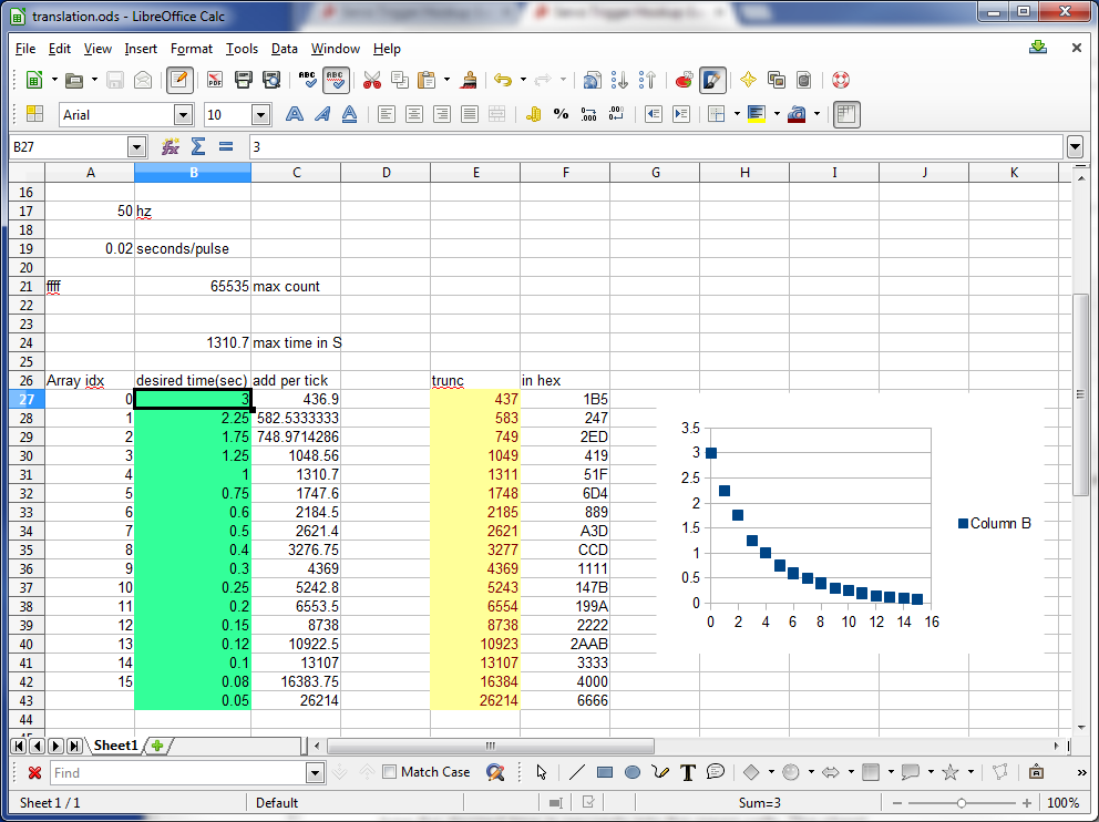
The range of transit times accessed by the T potentiometer is defined by a table of software values -- the table interprets pot position using an exponential curve, which allows for fine control of very short times on the low end, but still premits a useful longer range at the top. But perhaps these times don't fit your application especially well -- maybe you need extra resolution at the low end, or much longer times at the top end. You can change the timing table to do this.
The table is calculated using the "translation.ods" spreadsheet. Simply type the desired time in seconds into the green cells. The sheet recalculates the timing values, and updates the yellow cells. Cut and paste the yellow cells into the timelut array.
The table is only 17 entries long, which seems rather short -- but keep in mind we're using a microcontroller with only 8KB of flash memory and 512 Bytes of RAM -- we wouldn't want the timing table to fill the whole memory. To increase resolution between the table entries, the firmware performs linear interpolation to create more finely grained points in between.
Modes
The Servo Trigger comes with a couple of response modes that should be useful for most servo control needs, but in the case they're not a good fit, they can be modified.
There are several other modes hidden in the source file. In addition to the two default modes, there are three other modes. You can select among these by changing the compile-time symbols in the project. In Atmel Studio, select the "Servo Trigger" tab, then navigate to "Toolchain-> AVR/GNU C Compiler->Symbols" item.
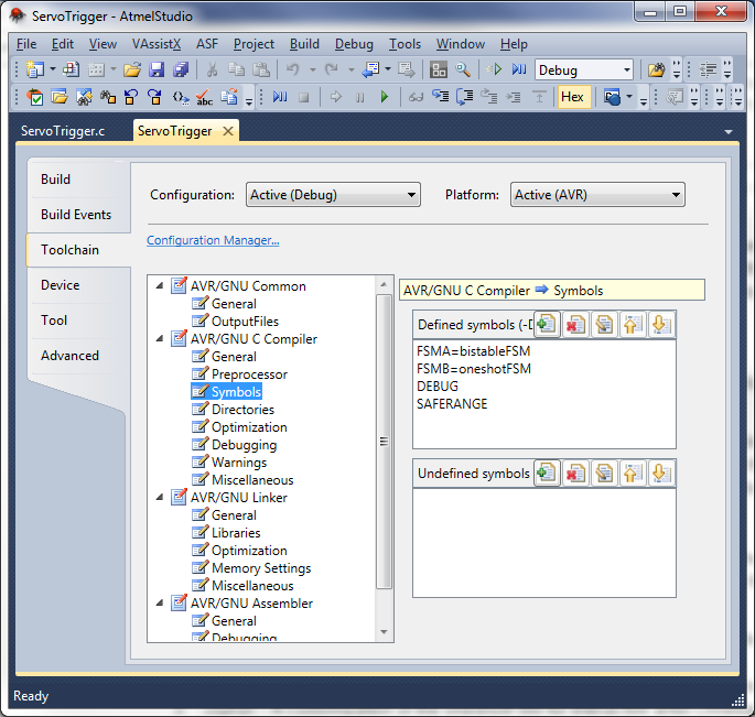
If you're using the command-line tools, the symbol definitions are found in the compiler invocation in the Makefile.
The FSMA and FSMB symbols determine which modes are programmed on the Servo Trigger. FSMA defines the unjumpered (default) mode, and FSMB defines the jumpered mode. There are five modes currently defined in the source file.
bistableFSM- The default mode - when the input is asserted, it moves from position A to B. While input is held, it will stay at B. When released, it moves back to A.oneshotFSM- Does a complete cycle every time the input is asserted - from A to B, then back to A.ctpFSM- A customization of the oneshotFSM for interactive artist Christopher T Palmer, which allows the B-to-A return cycle to be interrupted by a fresh input actuation.togglingFSM- Each time the input is asserted, it changes from A to B, or B to A. This mode is especially useful for driving continous rotation servos.astableFSM- When the input is asserted, it cycles back and forth between A and B. When the input is inactive, it sits where it was.
You can put any mode in either slot, or even put the same mode in both.
Implementation Details
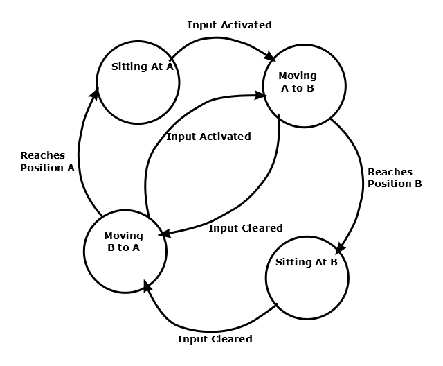
As you may have guessed from the names, the modes are implemented using Finite State Machines. Finite state machines are a design concept the defines a set of states, and a corresponding set of rules that determine how to transition between the states.
Within the Servo Trigger, each mode uses the same basic set of states, which in turn describe how it drives the servo. The states are:
- Sitting at position A.
- Moving from A to B.
- Sitting in position B.
- Moving from B to A.
The rules that define when the states can change can alter the behavior in significant ways. The different modes of the Servo Trigger are all implemented using the same states, but with different transition rules.
FSMs are commonly illustrated using "bubble diagrams," which draw the states as circles, and the rules as arrows between the circles. Here's the bubble diagram for the bistable FSM.
Building New State Machines
In the Servo Trigger, a state machine is implemented as a single function, which contains a switch statement wherein each state is a case. At the start of every PWM cycle, the state machine function is called to determine the pulse width, and possibly move to new states.
If you want to implement a new state machine, it can be useful to start by drawing the bubble diagram.
If your new FSM is a slight alteration to an existing one, the next best place to look at the existing FSMs -- it might be as simple as transplanting a state transition rule from one function to another. If your FSM is more ambitious, it's still useful to read and understand how the FSM interacts with the rest of the firmware.
Your application may need a subtle variation of an existing FSM, or a complete re-formulation. Since the source code is available, you're welcome to modify it to suit your needs!
Resources and Going Further
Now that you've got your Servo Trigger running, it's time to incorporate it into your own project!
If you have any feedback, please visit the comments or contact our technical support team at TechSupport@sparkfun.com.
Resources
- The design documentation is available for download from the Servo Trigger Github Repository.
- The firmware was developed using Atmel Studio, with a JTAG-ICE3 debug module.
- Without the JTAG-ICE, you can still reprogram the board with the Tiny programmer. You might want to use it with the pogopin adapter. You'll also need the command-line WinAVR tools.
Going Further
- The Servo Trigger can control any of our hobby servos.
- You can trigger it using many of our buttons and switches.
- The Open Servo is a different approach to controlling servo motors by enabling them to speak I2C.
- Wikipedia has a very detailed article about Finite State Machines.