SparkFun Inventor's Kit for micro:bit Experiment Guide
 D___Run___,
  bboyho
 Experiment 4: Driving an RGB LED
Introduction
You know what’s even more fun than a blinking LED? Changing colors with one LED. In this circuit, you’ll learn how to use an RGB LED to create unique color combinations. Depending on how bright each diode is, nearly any color is possible!
Parts Needed
You will need the following parts:
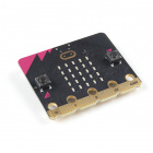
- 1x micro:bit
- 1x Micro B USB Cable
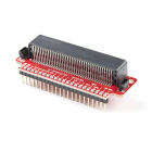
- 1x micro:bit Breakout (with Headers)
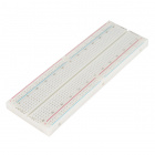
- 1x Breadboard
- 1x Jumper Wire
- 1x Common Cathode RGB LED
- 3x 100Ω Resistors
Didn't Get the SIK for micro:bit?
If you are conducting this experiment and didn't get the Inventor's Kit, we suggest using these parts:


Suggested Reading
Before continuing with this experiment, we recommend you be familiar with the concepts in the following tutorial:
Pulse Width Modulation
Introducing the Red/Green/Blue (RGB) LED
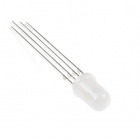
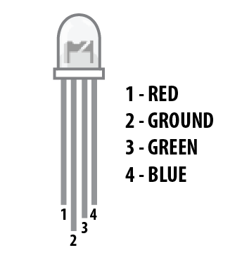
The Red/Green/Blue (RGB) LED is three LEDs in one. The RGB has four pins with each of the three shorter pins controlling an individual color: red, green or blue. The longer pin of the RGB is the common ground pin. You can create a custom-colored LED by turning different colors on and off to combine them. For example, if you turn on the red pin and green pin, the RGB will light up as yellow.

But which pin is which color? Pick up the RGB so that the longest pin (common ground) is aligned to the left as shown in the graphic below. The pins are Red, Ground, Green and Blue --- starting from the far left.
Hardware Hookup
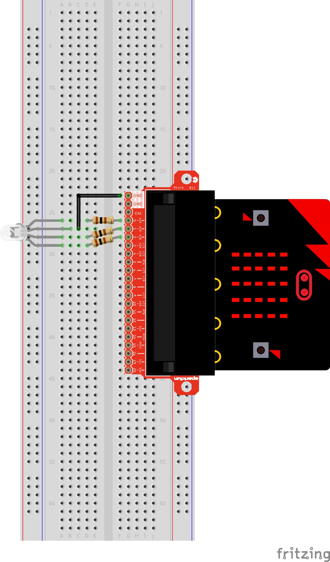
Ready to start hooking everything up? Check out the wiring diagram and hookup table below to see how everything is connected.
| Polarized Components | Pay special attention to the component’s markings indicating how to place it on the breadboard. Polarized components can only be connected to a circuit in one direction. |
Wiring Diagram for the Experiment
Run Your Script
Either copy and paste, or re-create the following code into your own MakeCode editor by clicking the open icon in the upper right-hand corner of the editor. You can also just download this example by clicking the download button in the lower right-hand corner of the code window.
Code to Note
Let's take a look at the code blocks in this experiment.
On Button Press
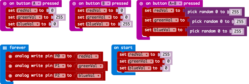
You will find the on Button Press block under the input block section. It is a different type of block than you are used to. It is what is called an event block --- code that is triggered when something happens, and only when that happens. In this case it is when one of the onboard buttons is pressed.
You can select between button A, button B and when both buttons (A+B) are pressed. Note that there is also a pin event function that works the same way, and you can use it with external buttons to build your own external hardware events.
Pick Random
In the on Buttons A+B pressed block you will notice that we set the color pin variables to random numbers using the pick random block. You give this block a range of values between 0 and another value. In this case we use 255, which is peak of the analog write block's output.
What You Should See
You should see your LED turn on red. If you press the A button on the micro:bit, the color will change to green; if you press the B button, the color will change to blue; and finally, if you press the A and B button, the RGB will turn a random color.

Troubleshooting
LED Remains Dark or Shows Incorrect Color
With the four pins of the LED so close together, it’s sometimes easy to misplace one. Double check that each pin is where it should be.
Seeing Red
The red diode within the RGB LED may be a bit brighter than the other two. To make your colors more balanced, use a higher ohm resistor.