SparkFun Inventor's Kit for micro:bit Experiment Guide
 D___Run___,
  bboyho
 Experiment 11: Using the Compass
Introduction
This experiment is just plain fun! Have you ever used a compass? Are you a little confused in terms of which direction to go? Fear not! We will build a digital compass that will keep you on track to the North Pole using the micro:bit's onboard compass chip!
Parts Needed
You will need the following parts:
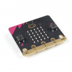
- 1x micro:bit
- 1x Micro B USB Cable
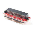
- 1x micro:bit Breakout (with Headers)
- 1x Breadboard
- 4x Jumper Wires
- 2x LEDs
- 2x 100Ω Resistors
Didn't Get the SIK for micro:bit?
If you are conducting this experiment and didn't get the Inventor's Kit, we suggest using these parts:


Introducing the Compass (Magnetometer)
In the previous experiment you learned about the accelerometer, which measured gravity. The compass, or technically the magnetometer, measures a magnetic field. Magnetic fields come in different sizes, but the biggest is the one produced by Earth itself, which is why compasses work.
The micro:bit has an onboard compass (a.k.a. a magnetometer) that can detect its orientation using Earth's magnetic field. Depending on the version that you have, the accelerometer and compass can be on separate ICs or combined into a single IC.
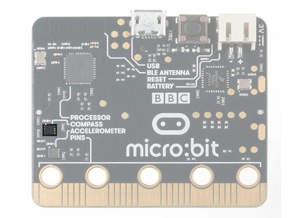 |
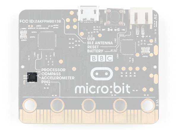 |
| v1.0 w/ Magnetometer On Separate IC | v1.5 w/ Combined Accelerometer and Magnetometer |
The magnetometer detects magnetic north and then represents your heading in degrees with north being 0 degrees, east being 90 degrees, south being 180 degrees and west being 270. Pretty cool! Now let's put this compass to good use!
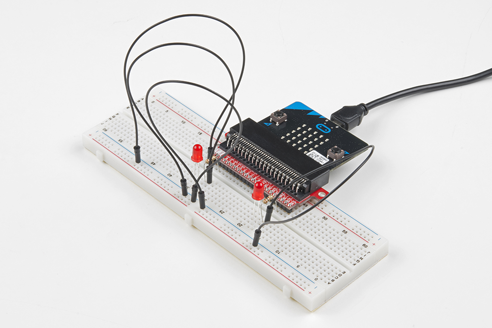
Hardware Hookup
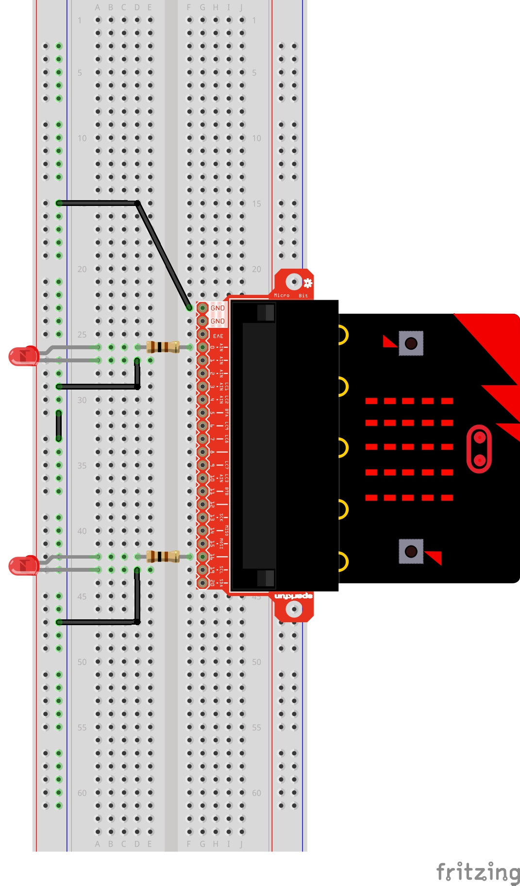
Ready to start hooking everything up? Check out the wiring diagram below to see how everything is connected.
| Polarized Components | Pay special attention to the component’s markings indicating how to place it on the breadboard. Polarized components can only be connected to a circuit in one direction. |
Wiring Diagram for the Experiment
Run Your Script
Either copy and paste, or re-create the following code into your own MakeCode editor by clicking the open icon in the upper right-hand corner of the editor window. You can also just download this example by clicking the download button in the lower right-hand corner of the code window.
Code to Note
Let's take a look at the code blocks in this experiment.
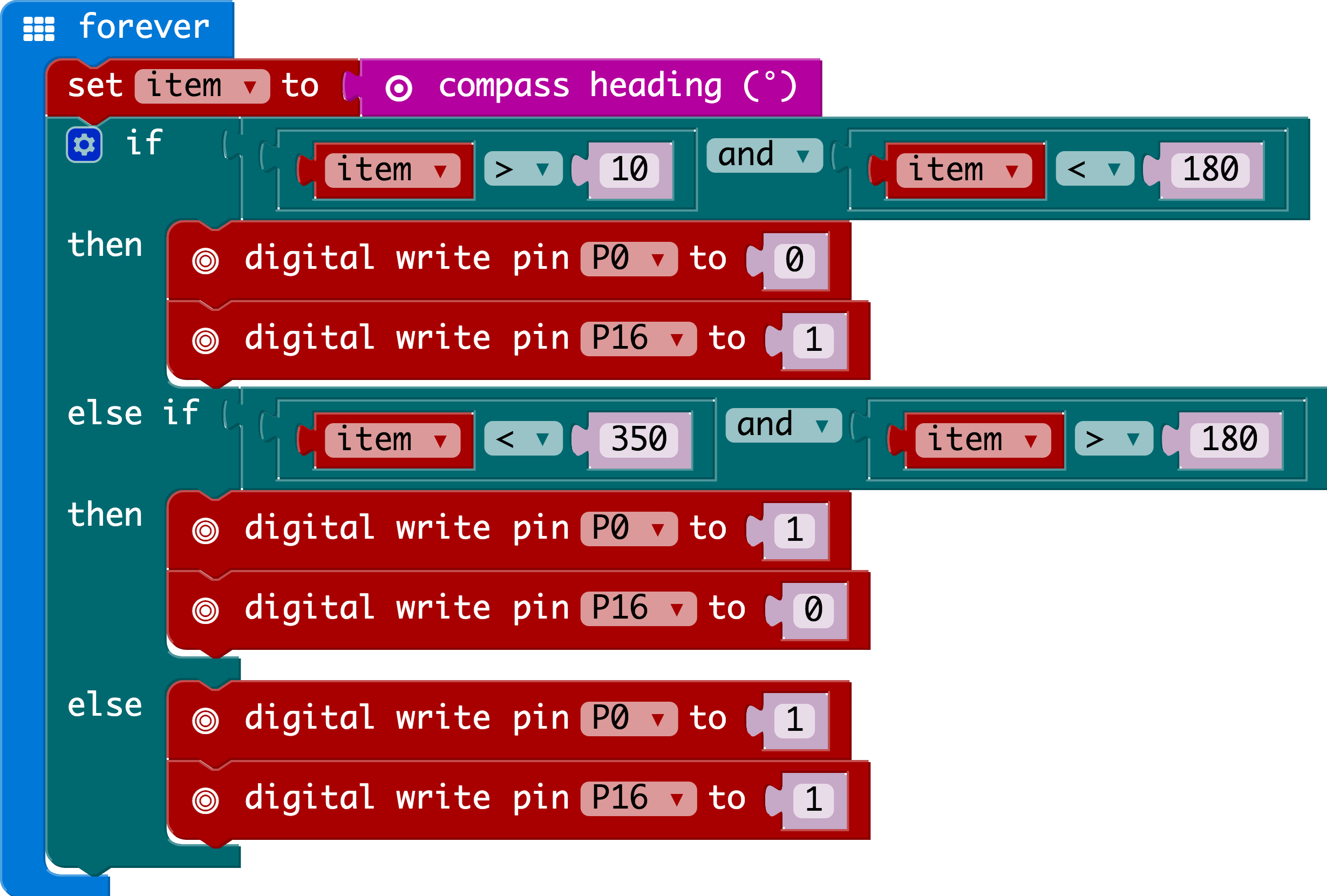
Compass Heading
The compass heading block returns the heading that you are facing if you are holding the micro:bit flat with the pins toward you. Zero degrees is north. We store this heading in a variable called item.
And
Much of the rest of this code is straightforward, but the logical and block is used. This combines two logical statements into one statement that returns true when both of the other statements are true and only true.
What You Should See
When your code is loaded you will first see instructions on the micro:bit LED array. The instructions will ask you to draw a circle, move the micro:bit around until all of the part of the circle have been added and it displays a smiley face. This process is to calibrate the micro:bit's magnetometer with its surroundings. The LEDs will start to turn on --- one or the other, or both. While standing still, rotate in the direction of the LED that is on. When both LEDs are lit, you are facing generally north (if you are outside)! You now have a compass that helps you find north, or any other direction you choose if you change the code!
Troubleshooting
Not Really North?
You may have a motor or magnet close by! The magnetometer is sensitive to all magnetic fields, including ones that may be produced by other electronics, metal, or even...a magnet.
LEDs Seem Backward
You might have your logical statement backward! Try flipping your greater than to less than, or the other way around.