SparkFun Inventor's Kit for micro:bit Experiment Guide
 D___Run___,
  bboyho
 Experiment 6: Reading a Button Press
Introduction
Up until now, we’ve focused mostly on outputs. Now we’re going to go to the other end of the spectrum and play around with inputs. In Experiment 2, we used an analog input to read the potentiometer. In this experiment, we’ll be reading one of the most common and simple inputs – a push button – by using a digital input. We will use it to cycle through different colors on the RGB.
Parts Needed
You will need the following parts:
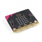
- 1x micro:bit
- 1x Micro B USB Cable
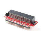
- 1x micro:bit Breakout (with Headers)
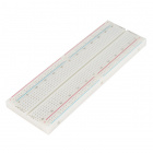
- 1x Breadboard
- 8x Jumper Wires
- 1x Momentary Push Button
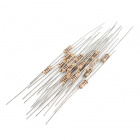
- 1x 10kΩ Resistor
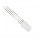
- 1x Common Cathode RGB LED
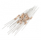
- 3x 100Ω Resistors
Didn't Get the SIK for micro:bit?
If you are conducting this experiment and didn't get the Inventor's Kit, we suggest using these parts:


Suggested Reading
Before continuing with this experiment, we recommend you be somewhat familiar with the concepts in these tutorials:
Button and Switch Basics
Analog vs. Digital
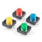
Introducing the Push Button
A momentary push button closes or completes the circuit only while it is being pressed. The button has four pins, which are broken out into two sets of two pins. When you press down on the button and get a nice "click," the button bridges the two sets of pins and allows current to flow through the circuit.
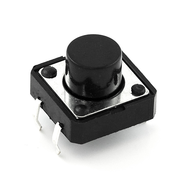
How do you know which pins are paired up? The buttons included in this kit will only fit across the breadboard ditch in one direction. Once you get the button pressed firmly into the breadboard (across the ditch), the pins are horizontally paired. The pins toward the top of the breadboard are connected, and the pins toward the button of the breadboard are connected.
Hardware Hookup
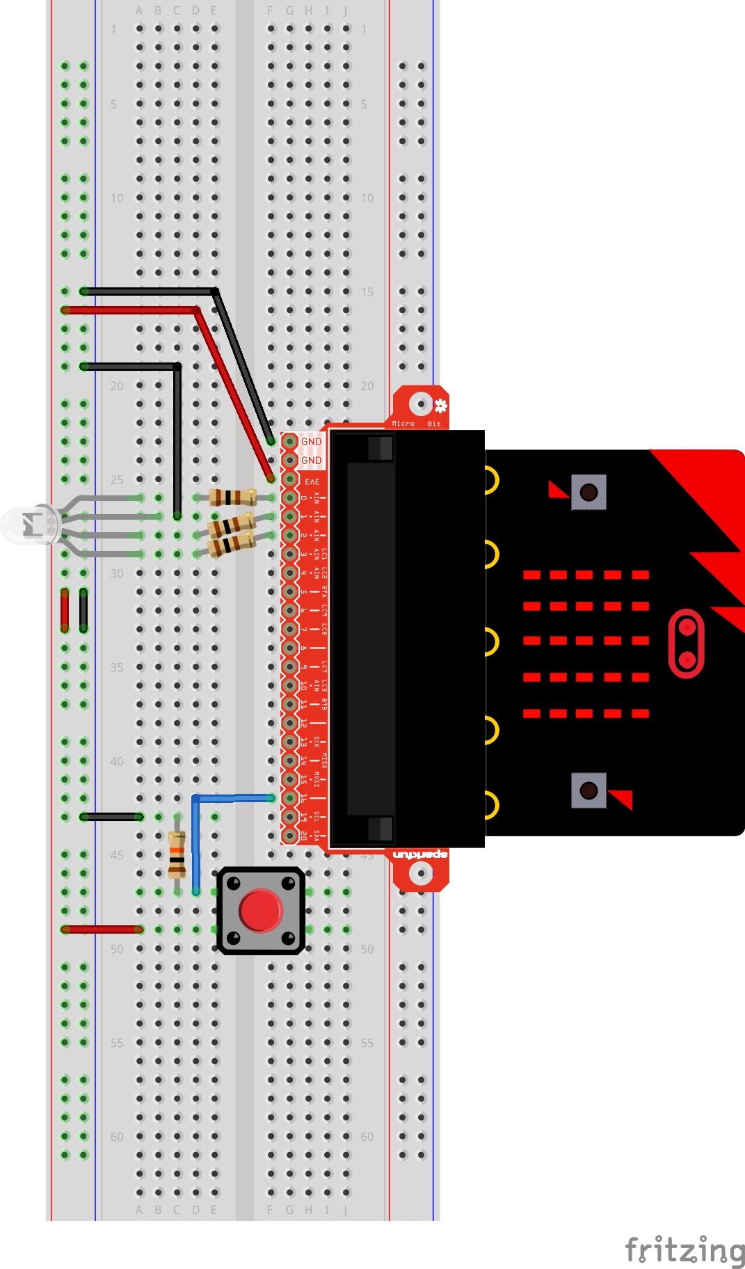
Ready to start hooking everything up? Check out the wiring diagram and hookup table below to see how everything is connected.
| Polarized Components | Pay special attention to the component’s markings indicating how to place it on the breadboard. Polarized components can only be connected to a circuit in one direction. |
Wiring Diagram for the Experiment
Run Your Script
Either copy and paste, or re-create the following code into your own MakeCode editor by clicking the open icon in the upper right-hand corner of the editor window. You can also just download this example by clicking the download button in the lower right-hand corner of the code window.
Code to Note
Let's take a look at the code blocks in this experiment.

Set Pull Pin
When you start your micro:bit, some pins can be set to be naturally on or naturally off. The set pull pin block allows you to set an initial state of a pin by selecting a pin and then its pull state, which is UP, DOWN or NONE.
Set Pin to Emit Event
Just like the button event in Experiment 4 there are events that you can read. But first, you have to set a pin to emit an event. You use the set pin to emit event block to create a type of event for a specific pin to emit or send out when it reaches that state. As an example, we set P16 to emit an EDGE event, which means that it changed from HIGH to LOW or LOW to HIGH.
On Event
Under the Advanced blocks you can find the Control blocks. These are the blocks that are the most complicated to use, but are the most powerful. The On Event block accepts an event type to watch for and a pin that event should happen on. When that specific event is emitted from that pin, it will trigger whatever code is inside of it. Take a moment to look through the list of different events that you can listen for!
if / Else if / Else
Finally, inside of the forever block is a more complex if block, which is an if / if else / else tree. To build this more complex "if" statement, add a standard if / else block into your program. Then click on this small gear in the upper left-hand corner of the block. This will open a tiny interface with more blocks in it. You can drag more else if blocks into the structure here to build your decision tree. Here is what ours looks like:
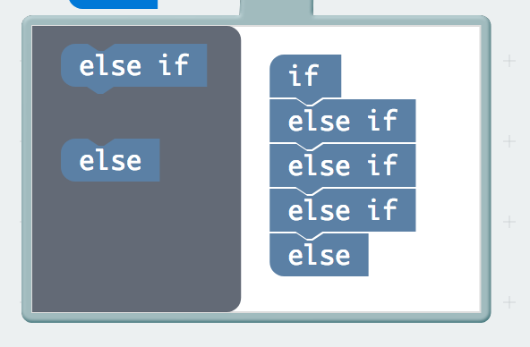
Once you are done rearranging your "if" statement you can close this menu by clicking on the gear again.
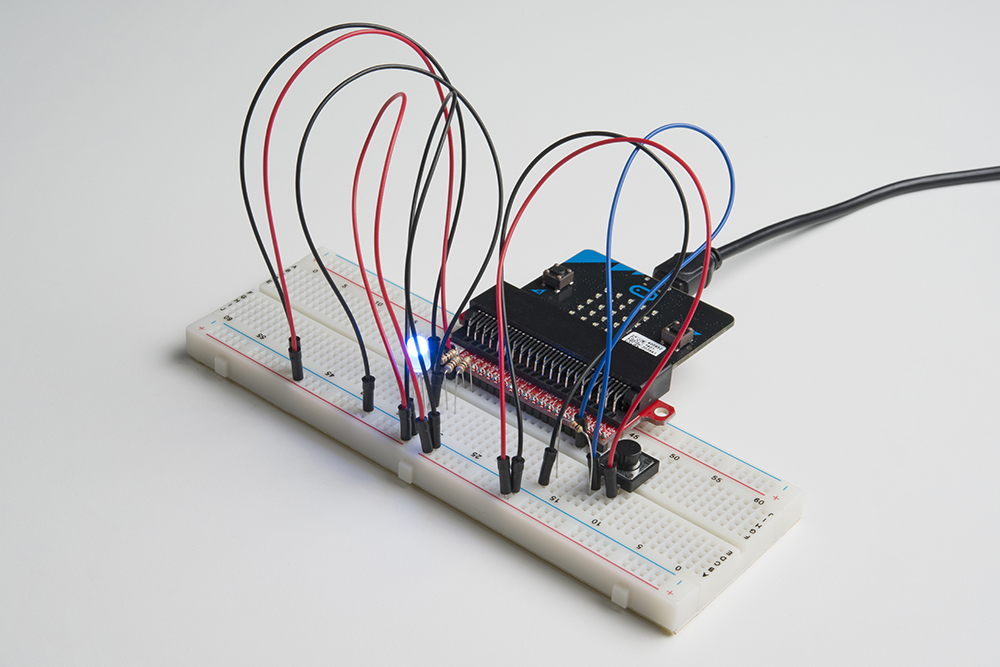
What You Should See
When you press the button, the RGB will turn on to a color. When you press it again, the color will change and another press will change the color once again. Press it one more time, and it will turn off. Every time you press the button, it increments a variable, and then we check against it to set the color. If the variable goes over the value of 2, we reset it to 0, which is off.
Troubleshooting
Light Not Turning On
The push button is square, and because of this it is easy to put it in the wrong way. Give it a 90-degree twist and see if it starts working.
Underwhelmed
No worries; these circuits are all super stripped-down to make playing with the components easy, but once you throw them together the sky is the limit.