SparkFun Inventor's Kit for micro:bit Experiment Guide
 D___Run___,
  bboyho
 Experiment 10: Using the Accelerometer
Introduction
In this experiment you will look at combining the use of the accelerometer on the micro:bit to measure the orientation of the micro:bit and use it to control the angle of a servo.
Ready to shake, rattle and roll?
Parts Needed
You will need the following parts:
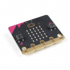
- 1x micro:bit
- 1x Micro B USB Cable
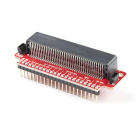
- 1x micro:bit Breakout (with Headers)
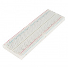
- 1x Breadboard
- 5x Jumper Wires
- 1x Servo
Didn't Get the SIK for micro:bit?
If you are conducting this experiment and didn't get the Inventor's Kit, we suggest using these parts:


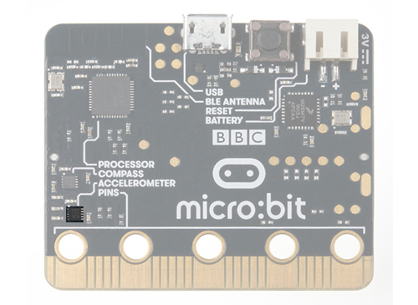
Introducing the Accelerometer
The accelerometer is a component that you won't find in the kit's bag of parts. Why? Because it is on the micro:bit itself! On the back of the micro:bit you can see a number of small chips. One of them is the accelerometer. The micro:bit has an onboard accelerometer that measures gravitational force. Depending on the version that you have, the accelerometer and compass can be on separate ICs or combined into a single IC.
 |
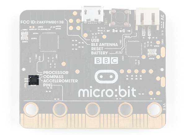 |
| v1.0 w/ Accelerometer on Sepearate IC | v1.5 w/ Combined Accelerometer and Magnetometer |
An accelerometer is a sensor that measures the gravitational forces pulling on it in all three dimensions of the chip's X, Y and Z axes.
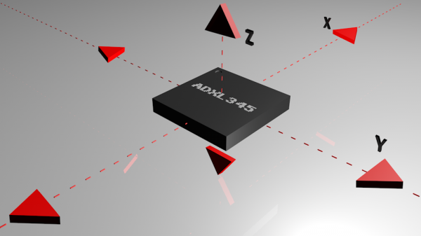
Not only can an accelerometer measure the raw forces pulling on the chip and the object that the chip is sitting on, but it can also detect steps, shakes and other motions that have a specific pattern. On top of that, you can use an accelerometer to simply detect the orientation that the device is in. Did you ever wonder how your phone knows when you turn it from portrait to landscape? It is all because of the accelerometer in your phone!
Hardware Hookup
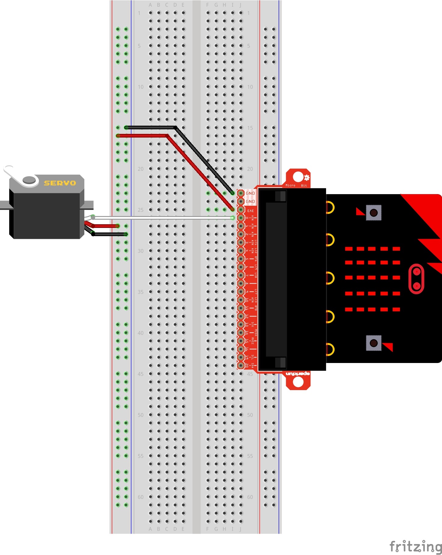
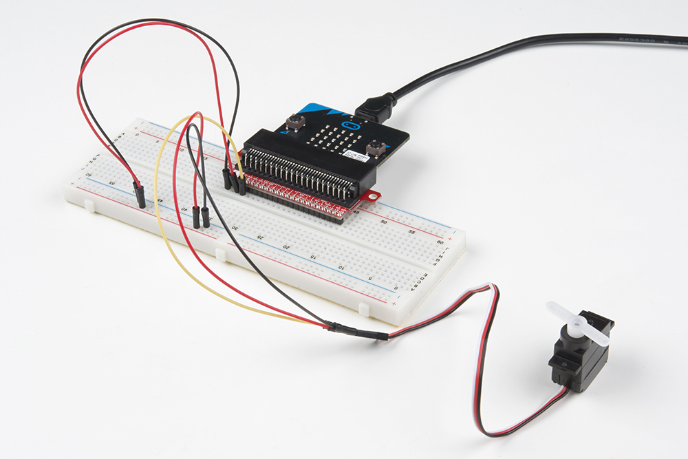
Ready to start hooking everything up? Check out the wiring diagram below to see how everything is connected.
| Polarized Components | Pay special attention to the component’s markings indicating how to place it on the breadboard. Polarized components can only be connected to a circuit in one direction. |
Wiring Diagram for the Experiment
Run Your Script
Either copy and paste, or re-create the following code into your own MakeCode editor by clicking the open icon in the upper right-hand corner of the editor window. You can also just download this example by clicking the download button in the lower right-hand corner of the code window.
Code to Note
Let's take a look at the code blocks in this experiment.

Acceleration
The acceleration block can be found under the input blocks group. This block returns the force of gravity pulling on a specific axis of the micro:bit (X, Y or Z) and represents that value as a range of numbers between -1023 and 1023. In this case, we measure the X axis, which is the side-to-side tilt of the micro:bit. If you tilt the micro:bit all the way to the left, you will get a -1023 value and all the way to the right is positive 1023.
Map
The map block looks intimidating, but it is one of the most useful blocks in MakeCode. The map block takes a given variable that has a known range --- in this case -1023 to 1023 --- and "maps" or scales that value range to another given range. The given range we want is 15 to 165, which is a good safe range of rotation for the servo. So, in the end -1023 ends up to equal 0, and 1023 ends up as 165 from the map block.
What You Should See
At the beginning of the program the servo should move to 90 degrees and then react to the orientation of the micro:bit. If you hold the micro:bit flat, the servo will be at 90 degrees. Then if you tilt the servo to the left, it will move less than 90 degrees toward the value of 15. If you move it to the right, the servo will move toward 165.
Troubleshooting
This Seems Backward
You may be holding the micro:bit in a different orientation. Flip it around and try again!
Servo Isn't Working
Double-check your wiring! Remember, red to 3.3 volts, black to ground, and white to signal.