SparkFun Inventor's Kit for micro:bit Experiment Guide
 D___Run___,
  bboyho
 Experiment 5: Reading an SPDT Switch
Introduction
In this experiment you will use your first digital input: a switch. The SPDT (Single-Pole, Double-Throw) switch is a simple way to select between two options, especially when paired with an if state. You will use that switch to select which of the two LEDs will blink.
Parts Needed
You will need the following parts:
- 1x micro:bit
- 1x Micro B USB Cable
- 1x micro:bit Breakout (with Headers)
- 1x Breadboard
- 8x Jumper Wires
- 1x SPDT Switch
- 2x LED (1 Red, 1 Yellow)
- 2x 100Ω Resistors
Didn't Get the SIK for micro:bit?
If you are conducting this experiment and didn't get the Inventor's Kit, we suggest using these parts:


Suggested Reading
Before continuing with this tutorial, we recommend you be somewhat familiar with the concepts in these tutorials:
Button and Switch Basics
Digital Logic
Introducing the Single-Pole, Double-Throw (SPDT) Switch
The Single-Pole, Double-Throw (SPDT) switch has a common pin in the middle and then two other pins. A connection will be made between the middle pin and one of the other pins depending on the position of the switch.

Reading a switch is similar to a button. You need to connect the common pin to a digital General Purpose Input/Output (GPIO) pin to the micro:bit board from a breadboard. The other pins can be connected to 3.3V and ground. It doesn’t matter which pin is which. When you move the switch, the common pin will either be HIGH (connected to 3.3V) or LOW (connected to ground).
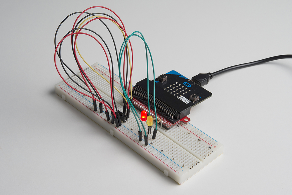
Hardware Hookup
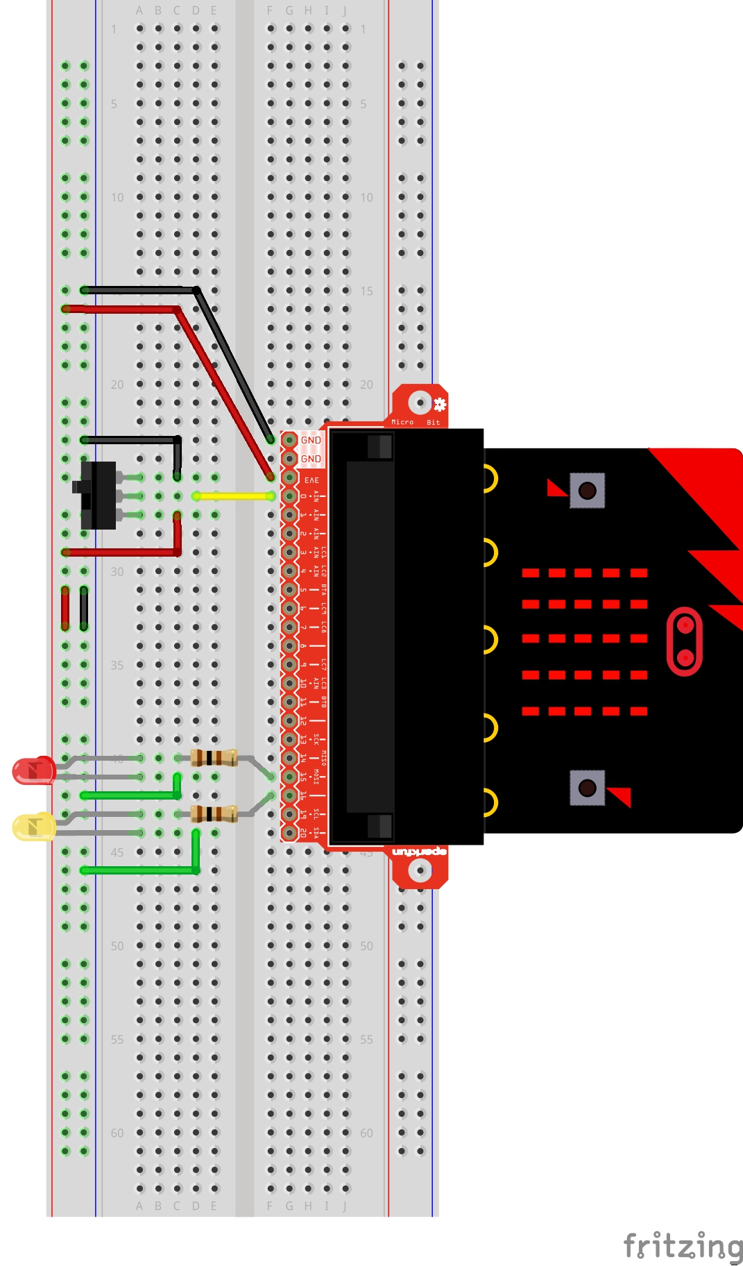
Ready to start hooking everything up? Check out the wiring diagram and hookup table below to see how everything is connected.
| Polarized Components | Pay special attention to the component’s markings indicating how to place it on the breadboard. Polarized components can only be connected to a circuit in one direction. |
Wiring Diagram for the Experiment
Run Your Script
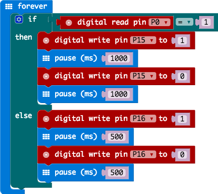
Either copy and paste, or re-create the following code into your own MakeCode editor by clicking the open icon in the upper right-hand corner of the editor window. You can also just download this example by clicking the download button in the lower right-hand corner of the code window.
Code to Note
Let's take a look at the code blocks in this experiment.
Digital Read
Just as the digital write block turns a pin on (1) or off (0) the digital read block looks at the state of a pin, which is either HIGH (1) or LOW (0). By building a circuit that connects 3.3V or ground to a pin, we can detect if a switch is thrown or a button pressed.
The digital read block returns a value so it is shaped to be inserted into a value slot and not a command. We use an equivalency block from the logic blocks to check if the pin is equal to 1 or 0 and then make a decision from there.
What You Should See
Depending on the state of the switch, a different LED will blink. If you move the switch to connect the signal pin to 3.3V (HIGH), then the LED connected to pin P15 will blink. If you flip the switch and ground the signal pin, then the LED on pin P16 will start blinking and LED 1 will turn off.
Troubleshooting
Light Not Turning On
The wires for the switch are right next to each other. Make sure that signal is in the center with voltage and ground on the outside pins. If you connect ground and voltage, your board will short out and shut down.
Make sure your power LED is on. If it is off, pull the signal wire and see if that changes anything. If you short circuit your micro:bit board, it will turn itself off to protect the circuitry.
Underwhelmed
No worries; these circuits are all super stripped-down to make playing with the components easy, but once you throw them together the sky is the limit.