SparkFun Inventor's Kit for micro:bit Experiment Guide
 D___Run___,
  bboyho
 Experiment 2: Reading a Potentiometer
Introduction
In this circuit you will work with a potentiometer. You will learn how to use a potentiometer to control the brightness of an LED by reading a sensor and storing its 0--1023 value as a variable, then using it as a brightness level for the LED.
Parts Needed
You will need the following parts:
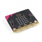
- 1x micro:bit
- 1x Micro B USB Cable
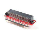
- 1x micro:bit Breakout (with Headers)
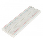
- 1x Breadboard
- 8x Jumper Wires
- 1x 10kΩ Potentiometer
- 1x LED
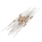
- 1x 100Ω Resistor
Didn't Get the SIK for micro:bit?
If you are conducting this experiment and didn't get the Inventor's Kit, we suggest using these parts:


Suggested Reading
Before continuing with this experiment, we recommend you be familiar with the concepts in the following tutorial:
Analog to Digital Conversion
Introducing the Potentiometer
A potentiometer is a resistance-based analog sensor that changes its internal resistance based on the rotation of its knob. The potentiometer has an internal voltage divider enabling you to read the change in voltage on the center pin with a microcontroller (i.e. micro:bit).
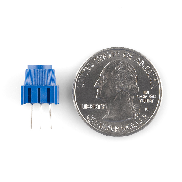
To hook up the potentiometer, attach the two outside pins to a supply voltage (3.3V in this circuit) and ground. It doesn’t matter which is connected where, as long as one is connected to power, and the other to ground. The center pin is then connected to an analog input pin so the micro:bit can measure the change in voltage. When you twist the knob, the sensor reading will change!
Hardware Hookup
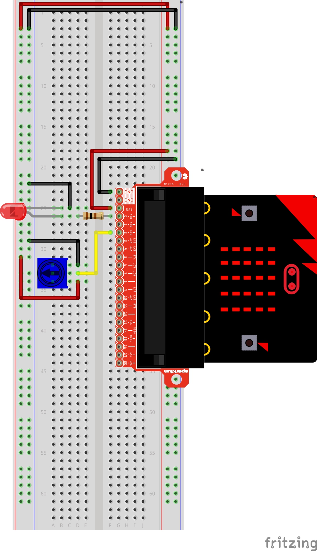
Ready to start hooking everything up? Check out the wiring diagram and hookup table below to see how everything is connected.
| Polarized Components | Pay special attention to the component’s markings indicating how to place it on the breadboard. Polarized components can only be connected to a circuit in one direction. |
Wiring Diagram for the Experiment
Running Your Script
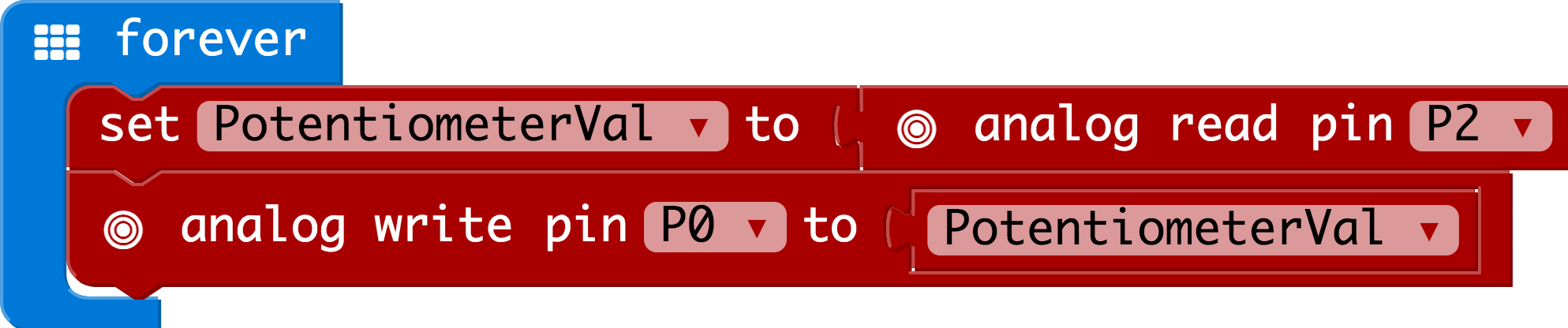
Either copy and paste, or re-create the following code into your own MakeCode editor by clicking the open icon in the upper right-hand corner of the editor. You can also just download this example by clicking the download button in the lower right-hand corner of the code window.
Code to Note
Let's take a look at the code blocks in this experiment.
A “variable” is a placeholder for values that may change in your code. You can create a variable using th Make Variable option underneath the Variables group. You can then name it, which then creates a block for your given variable.
Set To
To store a value inside of your newly created variable you use the set to block. The set to block allows you to select from a list of the variables that exist in your program and then add a value that you want to store or set that variables to.
Analog Read
In this program you are reading the voltage from the potentiometer which is 0 to 3.3 volts. The micro:bit reads that value as a 10 bit number which is a value range from 0 to 1023 using the analog read block. The analog read block is a value based block, meaning that you have to insert it into a block with a matching shape. We insert it into the set to block to store its value as a variable.
Analog Write
Just like the analog read block the analog write block deals with a range of values, but instead of reading a pin as an input the analog write block outputs an analog value to a pin. We see this as a brightness range with this led, but it could be a tone from a buzzer, a motor speed, etc. We set our analog output to the variable we stored the potentiometer value in.
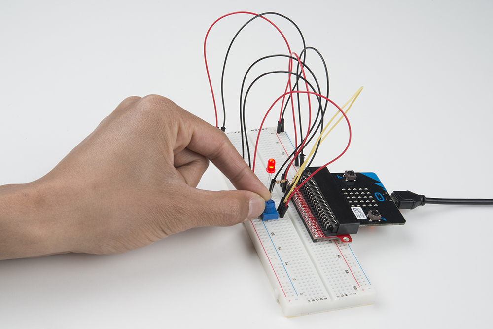
What You Should See
You should twist the potentiometer. You will notice that the LED will get brighter or dimmer based on the position of the potentiometer. If you turn the potentiometer all the way one direction it will be fully on and the other end will be fully off.
Troubleshooting
Sporadically Working
This is most likely due to a slightly dodgy connection with the potentiometer's pins. This can usually be conquered by holding the potentiometer down or moving the potentiometer circuit somewhere else on your breadboard.
Not Working
Make sure you haven’t accidentally connected the wiper (center pin), the resistive element in the potentiometer, to a wrong pin!
LED Not Lighting Up
LEDs will only work in one direction. Double check your connections.