SparkFun Inventor's Kit for micro:bit Experiment Guide
 D___Run___,
  bboyho
 Experiment 3: Reading a Photoresistor
Introduction
In Experiment 2, you got to use a potentiometer, which varies resistance based on the twisting of a knob and, in turn, changes the voltage being read by the analog input pin. In this circuit you’ll be using a photoresistor, which changes resistance based on how much light the sensor receives. You will read the light value of the room and have an LED turn on if it is dark and turn off if it is bright. That's right; you are going to build a night light!
Parts Needed
You will need the following parts:
- 1x micro:bit
- 1x Micro B USB Cable
- 1x micro:bit Breakout (with Headers)
- 1x Breadboard
- 8x Jumper Wires
- 1x Photoresistor
- 1x 10kΩ Resistor
- 1x LED
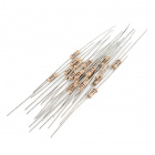
- 1x 100Ω Resistor
Didn't Get the SIK for micro:bit?
If you are conducting this experiment and didn't get the Inventor's Kit, we suggest using these parts:


Suggested Reading
Before continuing with this experiment, we recommend you be familiar with the concepts in the following tutorial:
Resistors
Voltage Dividers
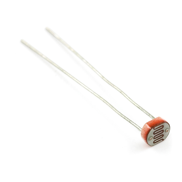
Introducing the Photoresistor
The photoresistor changes its resistance based on the light to which it is exposed.
To use this with the micro:bit, you will need to build a voltage divider with a 10kΩ resistor, as shown in the wiring diagram for this experiment. The micro:bit cannot read a change in resistance, only a change in voltage. A voltage divider allows you to translate a change in resistance to a corresponding voltage value.
The voltage divider enables the use of resistance-based sensors like the photoresistor in a voltage-based system. As you explore different sensors, you will find more resistance-based sensors that only have two pins like the photoresistor. To use them with your micro:bit you will need to build a voltage divider like the one in this experiment. To learn more about resistors in general, check out our tutorial on resistors and also our tutorial on voltage dividers if you have not already.
Hardware Hookup
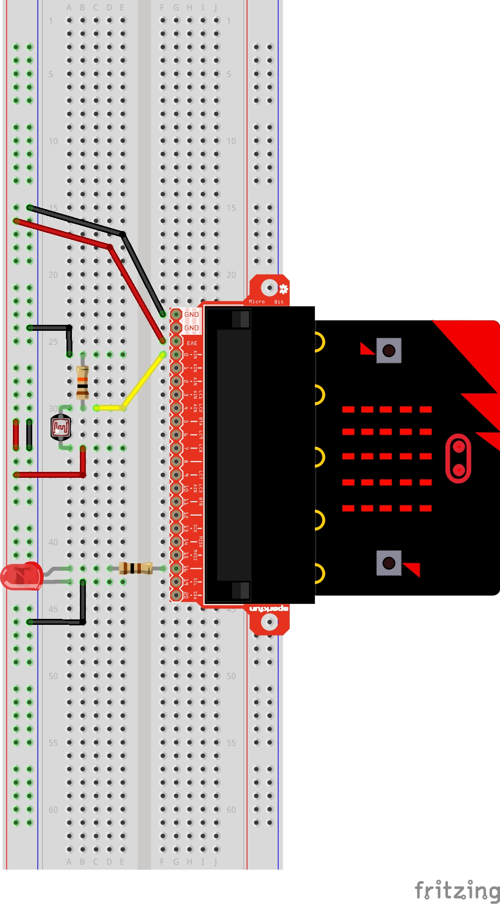
Ready to start hooking everything up? Check out the wiring diagram below to see how everything is connected.
| Polarized Components | Pay special attention to the component’s markings indicating how to place it on the breadboard. Polarized components can only be connected to a circuit in one direction. |
Wiring Diagram for the Experiment
Running Your Script
Either copy and paste, or re-create the following code into your own MakeCode editor by clicking the open icon in the upper right-hand corner of the editor. You can also just download this example by clicking the download button in the lower right-hand corner of the code window.
Code to Note
Let's take a look at the code blocks in this experiment.
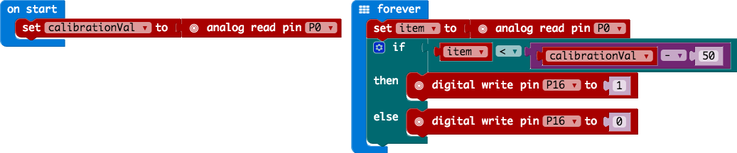
On Start
In previous experiments you have only used the forever block, which loops your code forever. The On start block is a block of code that only runs once at the very beginning of your program. In this program we use it to set a calibration value once, and then compare the changing value in the forever loop. This is a great spot for code that you only want to run a single time.
calibrationVal is a calibration variable. Your micro:bit takes a single reading of the light sensor in the on start block of code and uses this value to compare against the calibrationVal variable in the forever loop. This value doesn't change in the forever block, as it is set in the on start block. To update this value you can press the RESET button on the back of your micro:bit or power cycle the board.
If/Else
If the light value variable that is constantly being updated in the forever block is less than the calibration value minus 50, it is dark and the LED should turn on. The (-50) portion of the if block is a sensitivity value. The higher the value, the less sensitive the circuit will be; the lower the value, the more sensitive it will be to lighting conditions.
The if block is a logical structure. If the logical statement that is attached to it (item < calibrationVal -50) is true, then it will execute the code blocks inside of the if. If that statement is false, it will execute the else blocks. In this case if the statement is true (the room is dark), then the micro:bit will turn on the LED on pin 16; else (if the room is bright), it will turn the LED off using a digital write block.
What You Should See
When the micro:bit runs the program it will take a single reading from the light sensor and use that as a calibration value of the "normal" state of the room. When you place your hand over the light sensor or turn the lights off, the LED will turn on. If you turn the lights back on or uncover the light sensor, the LED will turn off.

Troubleshooting
LED Remains Dark
You may have been leaning over the light sensor when the code started. Make sure the light sensor is reading the normal light in the room at startup. Try resetting the micro:bit.
Still Not Quite Working
Double-check your wiring of the signal pin; sometimes you miss a breadboard connection by a row.