SparkFun Inventor's Kit Experiment Guide - v4.0
 Joel_E_B
Circuit 3A: Servo Motors
In this circuit, you will learn how to wire a servo and control it with code. Servo motors can be told to move to a specific position and stay there. Low-cost servo motors were originally used to steer remote-controlled airplanes and cars, but they have become popular for any project where precise movement is needed.
Parts Needed
Grab the following quantities of each part listed to build this circuit:

Additional Materials
- Scissors (NOT INCLUDED)
New Components
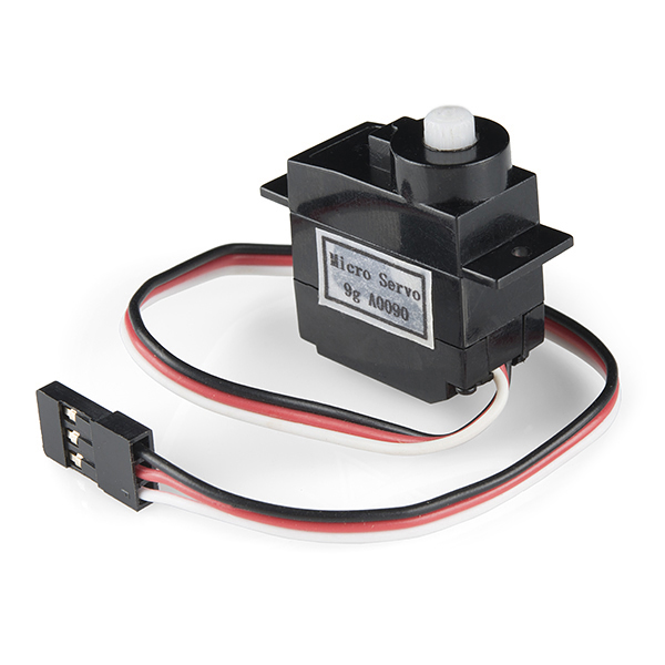
Servo Motors
Regular DC motors have two wires. When you hook the wires up to power, the motor spins around and around. Servo motors, on the other hand, have three wires: one for power, one for ground and one for signal. When you send the right signal through the signal wire, the servo will move to a specific angle and stay there. Common servos rotate over a range of 0° to 180°. The signal that is sent is a PWM signal, the same used to control the RGB LED in Project 1.
New Concepts
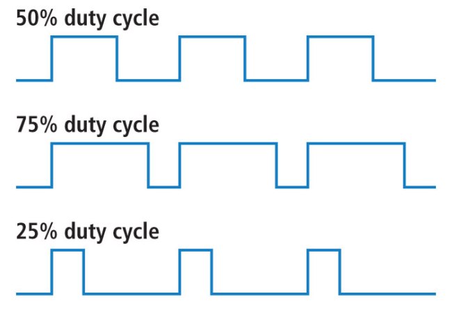
Duty Cycle
The Pulse Width Modulation (PWM) hardware available on a microcontroller is a great way to generate servo control signals. When talking about how long a PWM signal is on, this is referred to as duty cycle. Duty cycle is measured in percentage. The percentage of duty cycle specifically describes the percentage of time a digital signal is on over an interval or period of time. The variation in the duty cycle tells the servo which position to go to in its rotation.
Arduino Libraries
Writing code that sends precise PWM signals to the servo would be time consuming and would require a lot more knowledge about the servo. Luckily, the Arduino IDE has hundreds of built-in and user-submitted containers of code that are called libraries. One of the built-in libraries, the Servo Library, allows us to control a servo with just a few lines of code!
To use one of the built-in Arduino libraries, all you have to do is "include" a link to its header file. A header file is a smaller code file that contains definitions for all the functions used in that library. By adding a link to the header file in your code, you are enabling your code to use all of those library functions. To use the Servo Library, you would add the following line to the top of your sketch.
language:cpp
#include <Servo.h>
Objects and Methods
To use the Servo Library, you will have to start by creating a servo object, like this:
language:cpp
Servo myServo;
Objects look a lot like variables, but they can do much more. Objects can store values, and they can have their own functions, which are called methods.
The most used method that a servo object has is .write().
language:cpp
myServo.write(90);
The write method takes one parameter, a number from 0 to 180, and moves the servo arm to the specified position (in this case, degree 90).
Why would we want to go to the trouble of making an object and a method instead of just sending a servo control signal directly over a pin? First, the servo object does the work of translating our desired position into a signal that the servo can read. Second, using objects makes it easy for us to add and control more than one servo.
Hardware Hookup
| Polarized Components | Pay special attention to the component’s markings indicating how to place it on the breadboard. Polarized components can only be connected to a circuit in one direction. |
Servo motor connectors are polarized, but there is no place to attach them directly. Instead, connect three jumper wires to the female 3-pin header on the servo. This will make it so you can connect the servo to the breadboard.
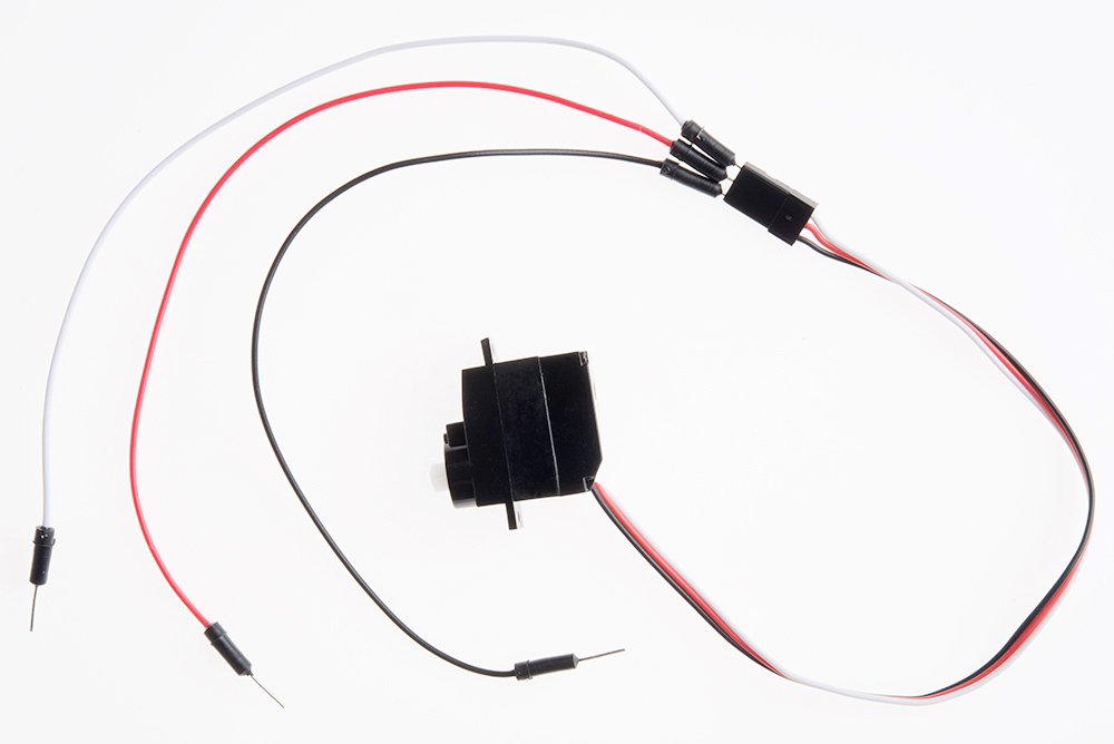
The servo wires are color coded to make hookup simple. The pin-out is as follows:
| Pin | Description |
|---|---|
| White | Signal - PWM In |
| Red | Power (5V) |
| Black | Ground (GND) |
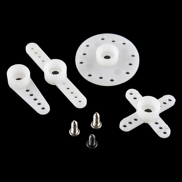
Included with your servo motor you will find a variety of motor mounts that connect to the shaft of your servo. You may choose to attach any mount you wish for this circuit. It will serve as a visual aid, making it easier to see the servo spin. The mounts will also come in handy at the end of this project.
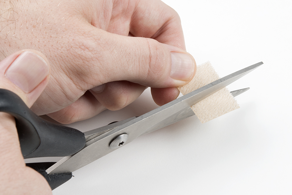
Affix the Servo (optional)
Included in your SIK is a strip of Dual Lock™. Cut a piece off the strip that is about ⅝ inch or 1.6cm. Then cut that strip in half to get two pieces that are roughly ⅝ inch x 1/2 inch or 1.6cm x 1.3cm.
Peel off the adhesive backing, and stick one half on the bottom of the servo motor.
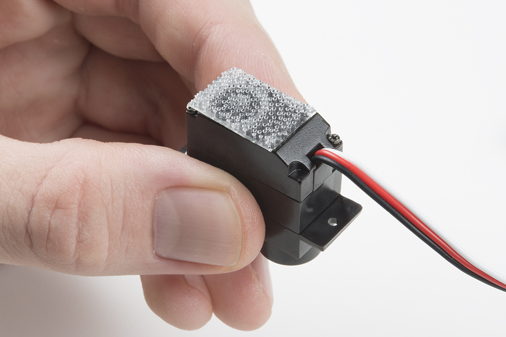
Stick the other half anywhere on the breadboard baseplate you want. Firmly press the bottom of the servo to the baseplate to temporarily adhere the two pieces of Dual Lock together. This will help stabilize the servo motor as it moves about.
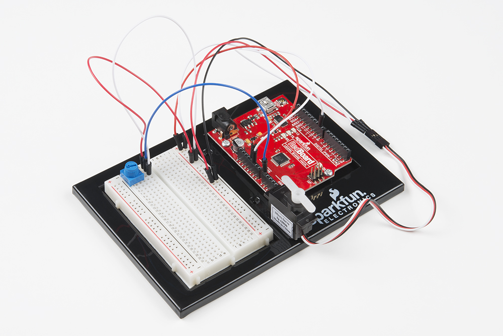
Ready to start hooking everything up? Check out the Fritzing diagram below to see how everything is connected.
Circuit Diagram
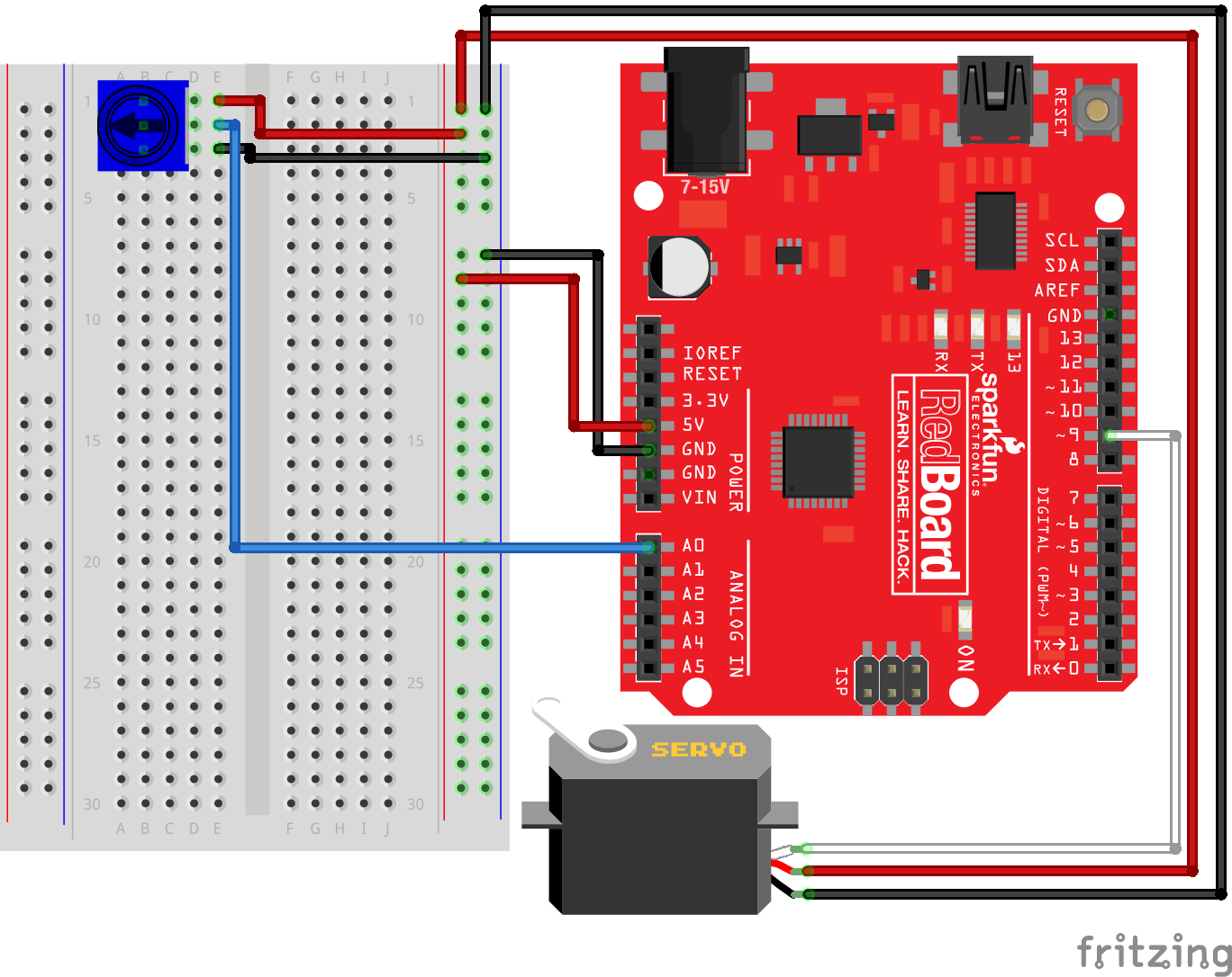
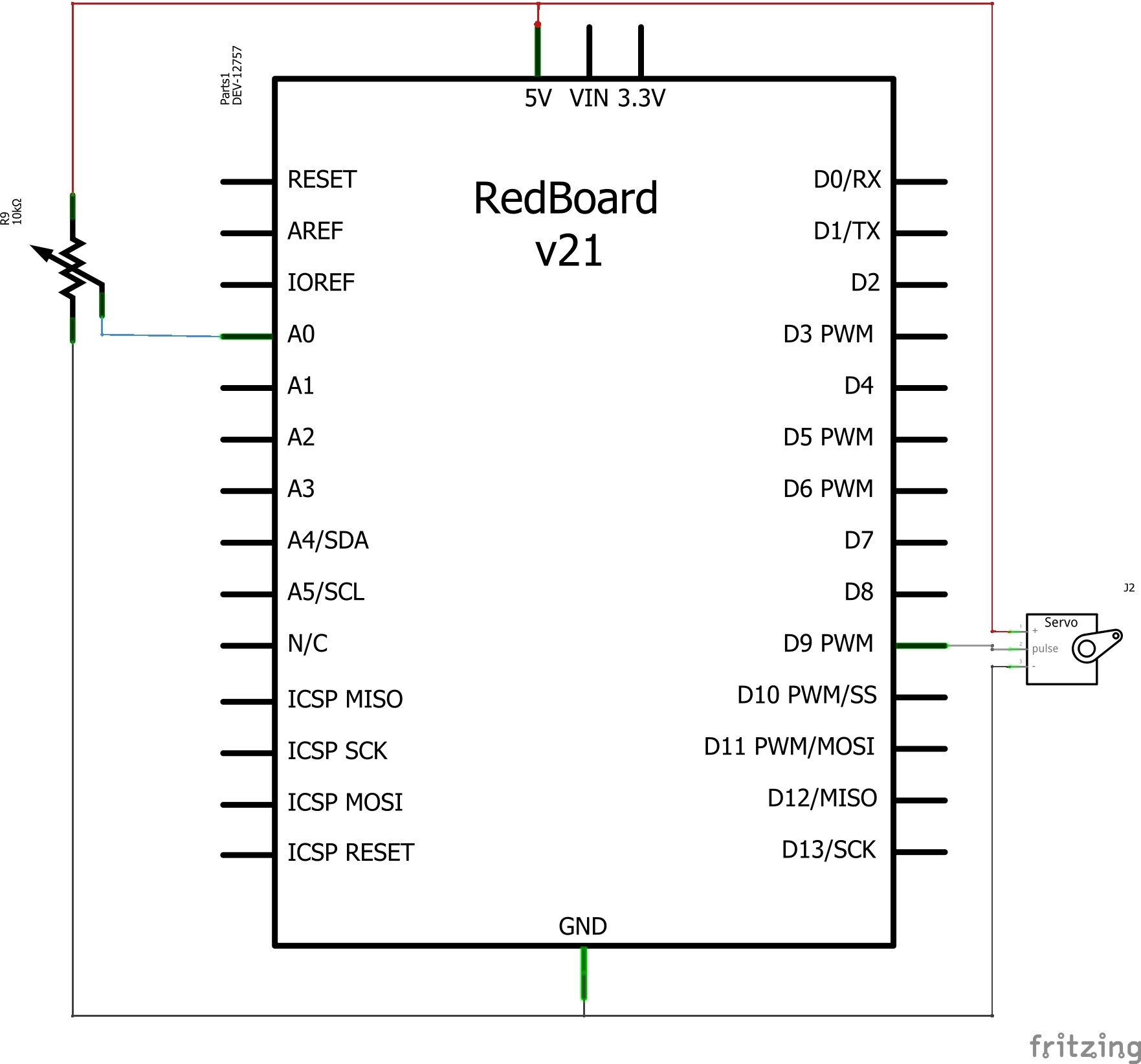
Having a hard time seeing the circuit? Click on the image for a closer look.
Hookup Table
| Component | RedBoard | Breadboard | Breadboard | Breadboard | Servo |
|---|---|---|---|---|---|
| Potentiometer | B1 | B2 | B3 | ||
| Jumper Wire | Analog Pin 0 | E2 | |||
| Jumper Wire | E1 | 5V Rail ( + ) | |||
| Jumper Wire | E3 | GND Rail ( - ) | |||
| Jumper Wire | 5V | 5V Rail ( + ) | |||
| Jumper Wire | GND | GND Rail ( - ) | |||
| Jumper Wire | Digital Pin 9 | White Servo Pin | |||
| Jumper Wire | 5V Rail ( + ) | Red Servo Pin | |||
| Jumper Wire | GND Rail ( - ) | Black Servo Pin |
Open the Sketch
To open the code, go to: File > Examples > SIK_Guide_Code-V_4 > SIK_Circuit_3A-Servo.
You can also copy and paste the following code into the Arduino IDE. Hit upload, and see what happens!
language:cpp
/*
  SparkFun Inventor’s Kit
  Circuit 3A-Servo

  Move a servo attached to pin 9 so that it's angle matches a potentiometer attached to A0.

  This sketch was written by SparkFun Electronics, with lots of help from the Arduino community.
  This code is completely free for any use.

  View circuit diagram and instructions at: https://learn.sparkfun.com/tutorials/sparkfun-inventors-kit-experiment-guide---v40
  Download drawings and code at: https://github.com/sparkfun/SIK-Guide-Code
*/

#include <Servo.h>          //include the servo library

int potPosition;           //this variable will store the position of the potentiometer
int servoPosition;         //the servo will move to this position

Servo myservo;              //create a servo object

void setup() {

  myservo.attach(9);        //tell the servo object that its servo is plugged into pin 9

}

void loop() {


  potPosition = analogRead(A0);                     //use analog read to measure the position of the potentiometer (0-1023)

  servoPosition = map(potPosition, 0, 1023, 20, 160); //convert the potentiometer number to a servo position from 20-160
                                                      //Note: its best to avoid driving the little SIK servos all the
                                                      //way to 0 or 180 degrees it can cause the motor to jitter, which is bad for the servo.

  myservo.write(servoPosition);                      //move the servo to the 10 degree position
}
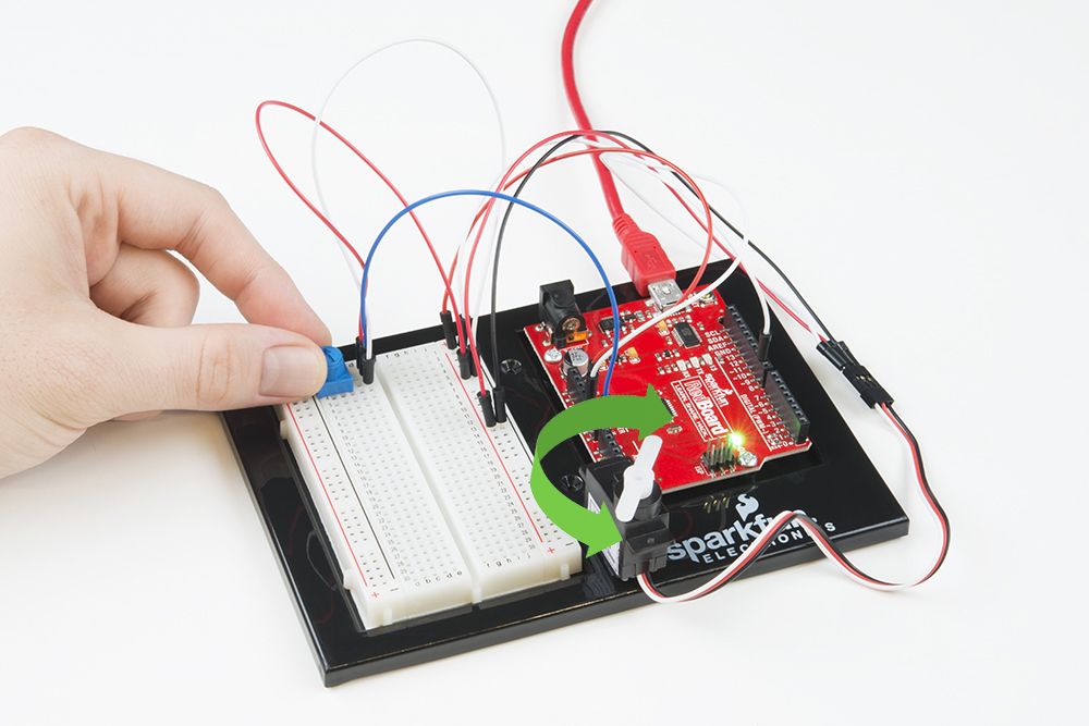
What You Should See
Turning the potentiometer will cause the servo to turn.
Program Overview
- Read the value of the potentiometer.
- Convert the potentiometer value (0--1023) to an angle (20--160).
- Tell the servo to go to this angle.
Code to Note
| Code | Description |
|---|---|
Including Libraries:#include <Servo.h> |
The #include command adds a library to your Arduino program. After you include a library, you can use the commands in the library in your program. This line adds the Servo library. |
Creating Servo Objects:Servo myServo; |
The Servo command creates a new servo object and assigns a name to it, myServo in this case. If you make more than one servo object, you will need to give them different names. |
Servo Attach:myServo.attach(9); |
The .attach() method tells the servo object to which pin the signal wire of its servo is attached. It will send position signals to this pin. In this sketch, pin 9 is used. Remember to only use digital pins that are capable of PWM. |
Range Mapping:map(potPosition, 0,1023,20,160); |
As shown in previous circuits, the analog pin values on your microcontroller vary from 0-1023. However, what if we want those values to control a servo motor that only accepts a value from 0-180? The answer is to use the map function. The map() function takes a range of values and outputs a different range of values that can contain more or less values than the original. In this case, we are taking the range 0-1023 and mapping it to the range 20-160. |
Servo Write:myServo.write(90); |
The .write() method moves the servo to a specified angle. In this example, the servo is being told to go to angle 90. |
Coding Challenges
| Challenge | Description |
|---|---|
| Reverse the direction | Try making the servo move in the opposite direction to the potentiometer. |
| Change the range | Try altering the map function so that moving the potentiometer a lot only moves the servo a little. |
| Swap in a different sensor | Try swapping a light sensor in for the potentiometer. You have just made a dial that reads how much light is present! |
Troubleshooting
| Problem | Solution |
|---|---|
| The servo doesn’t move | Check the wiring on your servo. Make sure that the red wire on the servo cord is connected to 5V, the black wire is connected to GND and the white signal wire is connected to pin 9. |
| The servo is twitching | Although these servos are supposed to move from 0 to 180 degrees, sometimes sending them to the extremes of their range causes them to twitch (the servo is trying to move farther than it can). Make sure that you aren’t telling the servo to move outside of the 20-160 degree range. |