SparkFun Inventor's Kit Experiment Guide - v4.0
 Joel_E_B
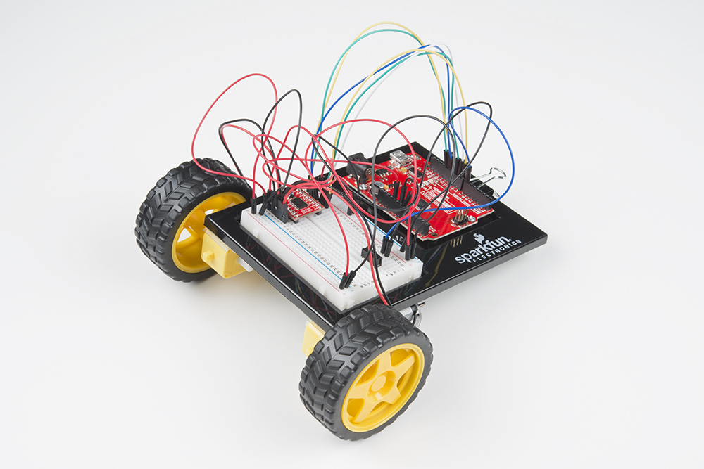
Circuit 5B: Remote-Controlled Robot
It’s remote control time! In this circuit, you’ll use a motor driver to control the speed and direction of two motors. You will also learn how to read multiple pieces of information from one serial command so that you can use the Serial Monitor to tell the robot what direction to move in and how far to move.
Parts Needed
Grab the following quantities of each part listed to build this circuit:

Additional Materials
- Scissors (NOT INCLUDED)
New Concepts
ASCII Characters
ASCII is a standard formalized in the 1960s that assigns numbers to characters. This is a method of character encoding. When typing on a computer keyboard, each character you type has a number associated with it. This is what allows computers to know whether you are typing a lowercase "a," an uppercase "A" or a random character such as ampersand (&). In this experiment, you will be sending characters to the Serial Monitor to move your remote control robot. When you send a character, the microcontroller is actually interpreting that as a specific number. There are tons of ASCII tables available online. These tables make it easier to know which character is represented by which number.
Converting Strings to Integers
String variables hold words like “dog” or “Robert Smith” that are made up of multiple characters. Arduino has a set of special built-in methods for string variables that you can call by putting a period after the variable name, as follows:
string_variable_name. toInt();
The .toInt() method converts the string to a number, and there are a dozen other methods that can do things like tell you the length of a word or change all of the characters in a string to uppercase or lowercase.
Hardware Hookup
| Polarized Components | Pay special attention to the component’s markings indicating how to place it on the breadboard. Polarized components can only be connected to a circuit in one direction. |
Before you build this circuit, you'll need to make a few modifications to the breadboard baseplate to make it more robot-like!
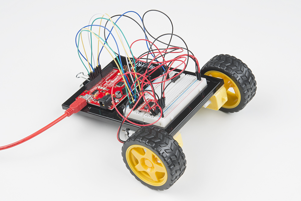
Assembling the Robot
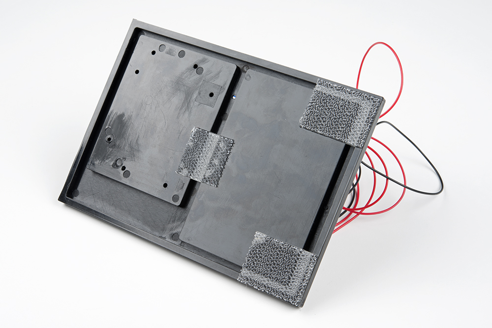
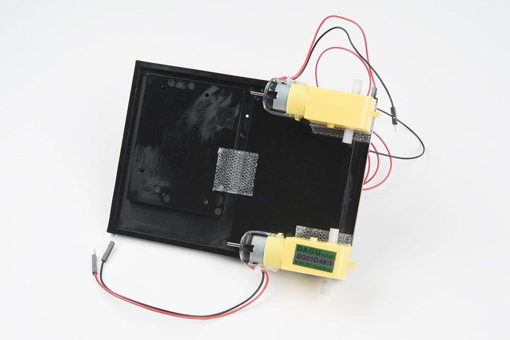
Using scissors, cut two strips of Dual Lock that are 1.25 inches (3.175cm) long and 1 inch (2.5cm) wide. Remove the adhesive backing, and attach the two pieces to the very corners of the baseplate on the side located under the breadboard.
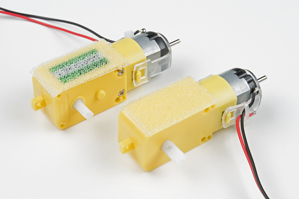
Cut two more strips that are 1.25 inches (3.175cm) long and 3/4 inch (1.9cm) wide. Remove the adhesive backing, and attach the strips to the two motors. Be sure that your motors are mirror images of each other when you attach the Dual Lock.
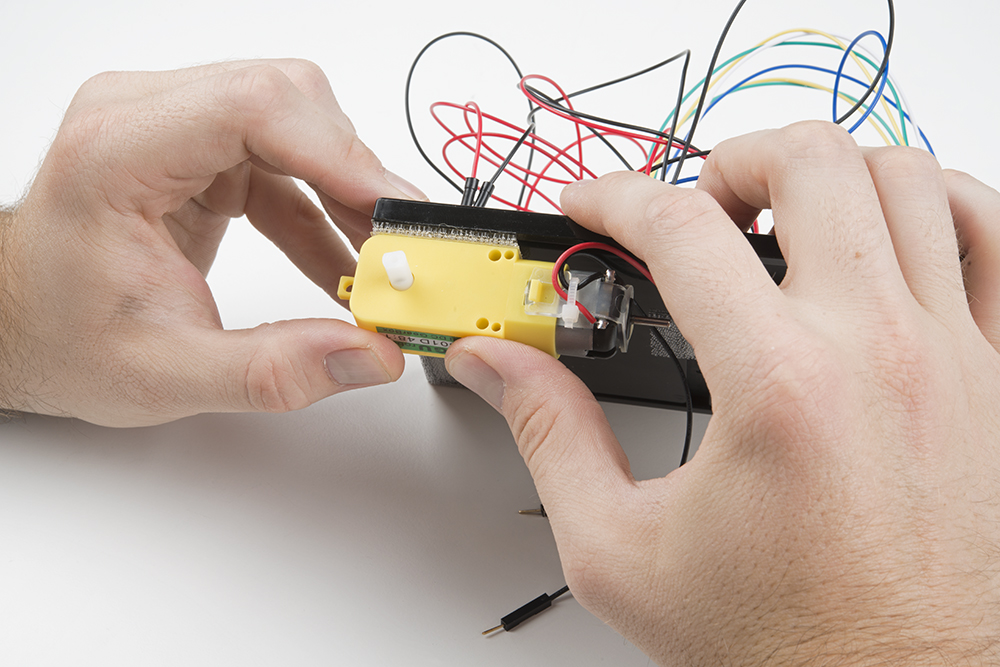
Press the motors to the baseplate, connecting the two Dual Lock surfaces. Try to get the motors as straight as possible so your robot will drive straight.
The bottom of your baseplate should look like the image below. Remember that the two motors should be mirror images of each other.
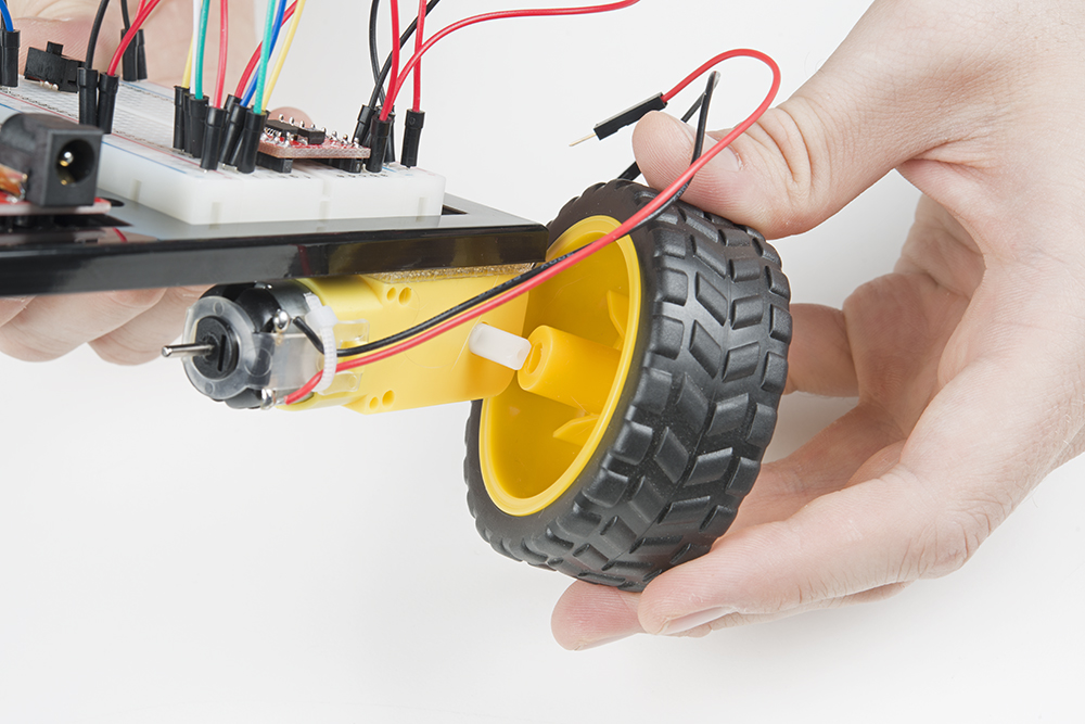
Attach the wheels by sliding them onto the plastic shafts on the gearmotor. The shaft is flat on one side, as is the wheel coupler. Align the two, and then press to fit the wheel onto the shaft.
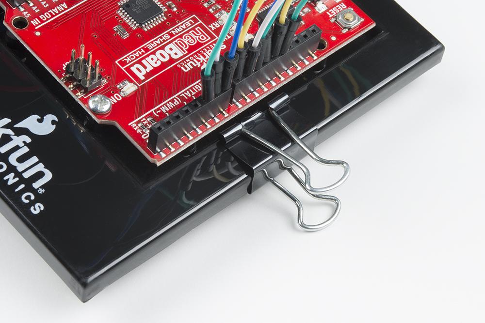
Last, clip the binder clip onto the back end of the robot. This will act as a caster as the robot drives around.
Once you're finished, it's time to build the circuit. You may choose to remove the motors or leave them on while you build the circuit.
Ready to start hooking everything up? Check out the circuit diagram and hookup table below to see how everything is connected.
Circuit Diagram
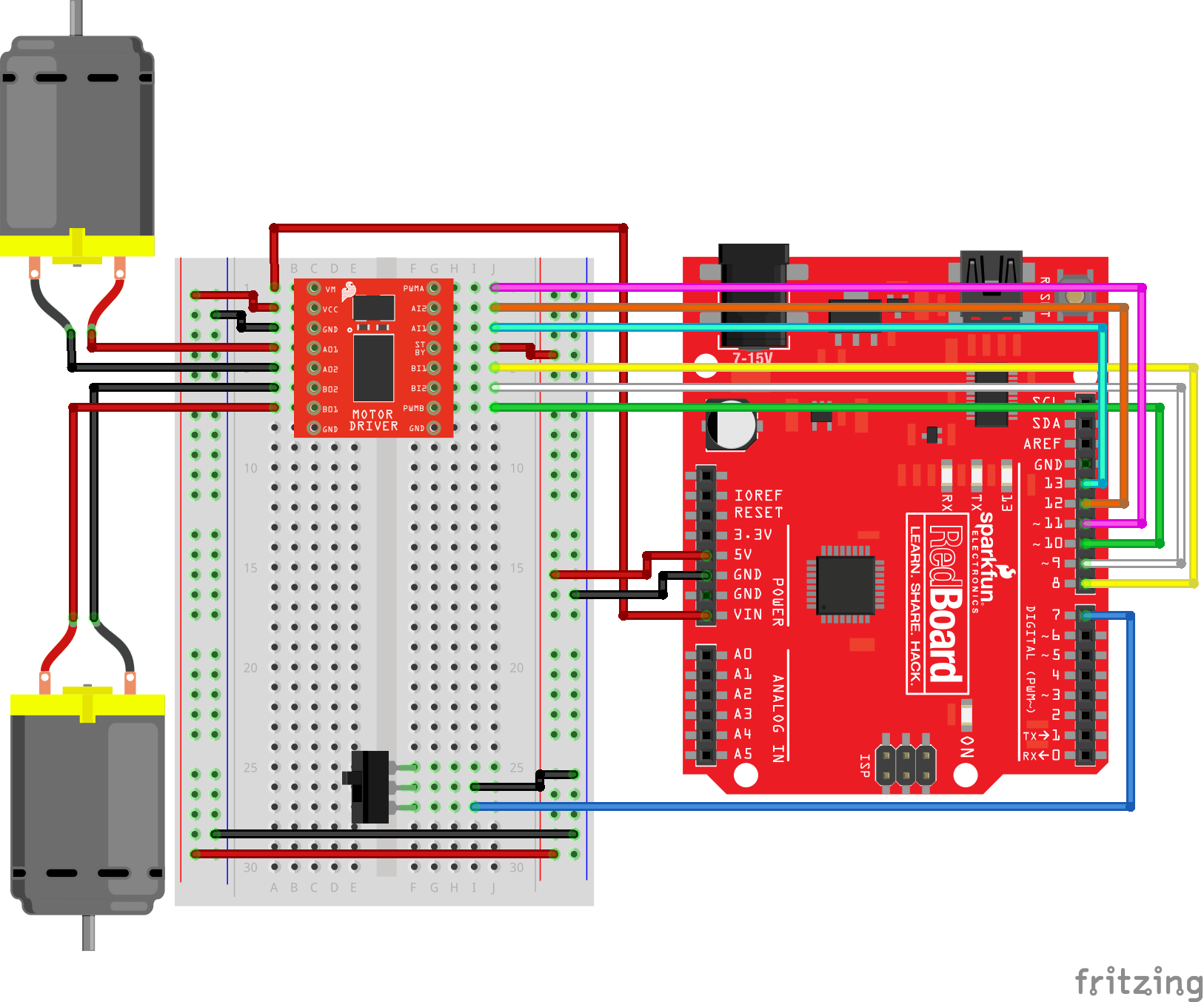
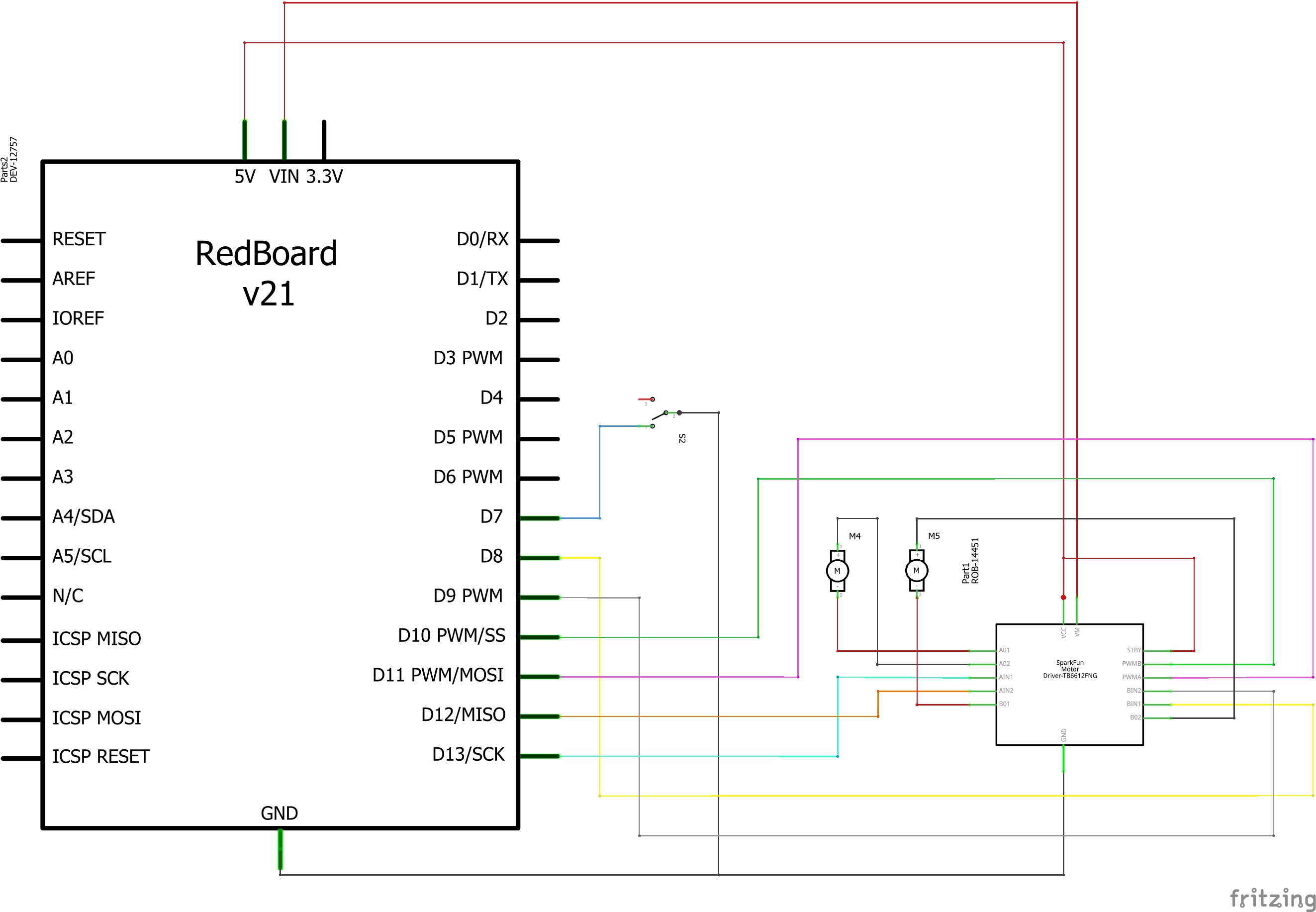
Having a hard time seeing the circuit? Click on the image for a closer look.
Hookup Table
| Component | RedBoard | Breadboard | Breadboard | Breadboard |
|---|---|---|---|---|
| Jumper Wire | 5V | 5V Rail ( + ) | ||
| Jumper Wire | GND | GND Rail ( - ) | ||
| Jumper Wire | 5V Rail ( + ) | 5V Rail ( + ) | ||
| Jumper Wire | GND Rail ( - ) | GND Rail ( - ) | ||
| Jumper Wire | VIN | A1 | ||
| Motor Driver | C1-C8 (VM on C1) | G1-G8 (PWMA on G1) | ||
| Jumper Wire | A2 | 5V Rail ( + ) | ||
| Jumper Wire | A3 | GND Rail ( - ) | ||
| Jumper Wire | Digital Pin 8 | J5 | ||
| Jumper Wire | Digital Pin 9 | J6 | ||
| Jumper Wire | Digital Pin 10 | J7 | ||
| Jumper Wire | J4 | 5V Rail ( + ) | ||
| Jumper Wire | Digital Pin 11 | J1 | ||
| Jumper Wire | Digital Pin 12 | J2 | ||
| Jumper Wire | Digital Pin 13 | J3 | ||
| Motor 1 (Right) | A4 (Red +) | A5 (Black -) | ||
| Motor 2 (Left) | A6 (Black -) | A7 (Red +) | ||
| Switch | F25 | F26 | F27 | |
| Jumper Wire | I26 | GND Rail ( - ) | ||
| Jumper Wire | Digital Pin 7 | I27 |
Open the Sketch
To open the code, go to: File > Examples > SIK_Guide_Code-V_4 > SIK_Circuit_5B-RemoteControlRobot
You can also copy and paste the following code into the Arduino IDE. Hit upload, and see what happens!
language:cpp
/*
  SparkFun Inventor’s Kit
  Circuit 5B - Remote Control Robot

  Control a two wheeled robot by sending direction commands through the serial monitor.
  This sketch was adapted from one of the activities in the SparkFun Guide to Arduino.
  Check out the rest of the book at
  https://www.sparkfun.com/products/14326

  This sketch was written by SparkFun Electronics, with lots of help from the Arduino community.
  This code is completely free for any use.

  View circuit diagram and instructions at: https://learn.sparkfun.com/tutorials/sparkfun-inventors-kit-experiment-guide---v40
  Download drawings and code at: https://github.com/sparkfun/SIK-Guide-Code
*/


//the right motor will be controlled by the motor A pins on the motor driver
const int AIN1 = 13;           //control pin 1 on the motor driver for the right motor
const int AIN2 = 12;            //control pin 2 on the motor driver for the right motor
const int PWMA = 11;            //speed control pin on the motor driver for the right motor

//the left motor will be controlled by the motor B pins on the motor driver
const int PWMB = 10;           //speed control pin on the motor driver for the left motor
const int BIN2 = 9;           //control pin 2 on the motor driver for the left motor
const int BIN1 = 8;           //control pin 1 on the motor driver for the left motor

int switchPin = 7;             //switch to turn the robot on and off

const int driveTime = 20;      //this is the number of milliseconds that it takes the robot to drive 1 inch
                               //it is set so that if you tell the robot to drive forward 25 units, the robot drives about 25 inches

const int turnTime = 8;        //this is the number of milliseconds that it takes to turn the robot 1 degree
                               //it is set so that if you tell the robot to turn right 90 units, the robot turns about 90 degrees

                               //Note: these numbers will vary a little bit based on how you mount your motors, the friction of the
                               //surface that your driving on, and fluctuations in the power to the motors.
                               //You can change the driveTime and turnTime to make them more accurate

String botDirection;           //the direction that the robot will drive in (this change which direction the two motors spin in)
String distance;               //the distance to travel in each direction

/********************************************************************************/
void setup()
{
  pinMode(switchPin, INPUT_PULLUP);   //set this as a pullup to sense whether the switch is flipped

  //set the motor control pins as outputs
  pinMode(AIN1, OUTPUT);
  pinMode(AIN2, OUTPUT);
  pinMode(PWMA, OUTPUT);

  pinMode(BIN1, OUTPUT);
  pinMode(BIN2, OUTPUT);
  pinMode(PWMB, OUTPUT);

  Serial.begin(9600);           //begin serial communication with the computer

  //prompt the user to enter a command
  Serial.println("Enter a direction followed by a distance.");
  Serial.println("f = forward, b = backward, r = turn right, l = turn left");
  Serial.println("Example command: f 50");
}

/********************************************************************************/
void loop()
{
  if (digitalRead(7) == LOW)
  {                                                     //if the switch is in the ON position
    if (Serial.available() > 0)                         //if the user has sent a command to the RedBoard
    {
      botDirection = Serial.readStringUntil(' ');       //read the characters in the command until you reach the first space
      distance = Serial.readStringUntil(' ');           //read the characters in the command until you reach the second space

      //print the command that was just received in the serial monitor
      Serial.print(botDirection);
      Serial.print(" ");
      Serial.println(distance.toInt());

      if (botDirection == "f")                         //if the entered direction is forward
      {
        rightMotor(200);                                //drive the right wheel forward
        leftMotor(200);                                 //drive the left wheel forward
        delay(driveTime * distance.toInt());            //drive the motors long enough travel the entered distance
        rightMotor(0);                                  //turn the right motor off
        leftMotor(0);                                   //turn the left motor off
      }
      else if (botDirection == "b")                    //if the entered direction is backward
      {
        rightMotor(-200);                               //drive the right wheel forward
        leftMotor(-200);                                //drive the left wheel forward
        delay(driveTime * distance.toInt());            //drive the motors long enough travel the entered distance
        rightMotor(0);                                  //turn the right motor off
        leftMotor(0);                                   //turn the left motor off
      }
      else if (botDirection == "r")                     //if the entered direction is right
      {
        rightMotor(-200);                               //drive the right wheel forward
        leftMotor(255);                                 //drive the left wheel forward
        delay(turnTime * distance.toInt());             //drive the motors long enough turn the entered distance
        rightMotor(0);                                  //turn the right motor off
        leftMotor(0);                                   //turn the left motor off
      }
      else if (botDirection == "l")                   //if the entered direction is left
      {
        rightMotor(255);                                //drive the right wheel forward
        leftMotor(-200);                                //drive the left wheel forward
        delay(turnTime * distance.toInt());             //drive the motors long enough turn the entered distance
        rightMotor(0);                                  //turn the right motor off
        leftMotor(0);                                   //turn the left motor off
      }
    }
  }
  else
  {
    rightMotor(0);                                  //turn the right motor off
    leftMotor(0);                                   //turn the left motor off
  }
}
/********************************************************************************/
void rightMotor(int motorSpeed)                       //function for driving the right motor
{
  if (motorSpeed > 0)                                 //if the motor should drive forward (positive speed)
  {
    digitalWrite(AIN1, HIGH);                         //set pin 1 to high
    digitalWrite(AIN2, LOW);                          //set pin 2 to low
  }
  else if (motorSpeed < 0)                            //if the motor should drive backward (negative speed)
  {
    digitalWrite(AIN1, LOW);                          //set pin 1 to low
    digitalWrite(AIN2, HIGH);                         //set pin 2 to high
  }
  else                                                //if the motor should stop
  {
    digitalWrite(AIN1, LOW);                          //set pin 1 to low
    digitalWrite(AIN2, LOW);                          //set pin 2 to low
  }
  analogWrite(PWMA, abs(motorSpeed));                 //now that the motor direction is set, drive it at the entered speed
}

/********************************************************************************/
void leftMotor(int motorSpeed)                        //function for driving the left motor
{
  if (motorSpeed > 0)                                 //if the motor should drive forward (positive speed)
  {
    digitalWrite(BIN1, HIGH);                         //set pin 1 to high
    digitalWrite(BIN2, LOW);                          //set pin 2 to low
  }
  else if (motorSpeed < 0)                            //if the motor should drive backward (negative speed)
  {
    digitalWrite(BIN1, LOW);                          //set pin 1 to low
    digitalWrite(BIN2, HIGH);                         //set pin 2 to high
  }
  else                                                //if the motor should stop
  {
    digitalWrite(BIN1, LOW);                          //set pin 1 to low
    digitalWrite(BIN2, LOW);                          //set pin 2 to low
  }
  analogWrite(PWMB, abs(motorSpeed));                 //now that the motor direction is set, drive it at the entered speed
}
What You Should See
Open the Serial Monitor. It should prompt you to enter a command that contains a direction and distance. When you type a direction and distance into the serial monitor the robot will move or turn.
Program Overview
- Prompt the user to enter a command and list the shortcuts for the directions.
- Wait for a serial command.
- Read the first part of the serial command and set that as the direction. Then read the second part of the command and set it as the distance: a. If the direction is “f”, drive both motors forward for the distance. b. If the direction is “b”, drive both motors backward for the distance. c. If the direction is “r”, drive the right motor backward and the left motor forward. d. If the direction is “l”, drive the left motor backward and the right motor forward.
Code to Note
| Code | Description |
|---|---|
Parsing Strings:Serial.readStringUntil(‘ ‘); | Reads a serial message until the first space and saves it as a string. |
String to Int:string_name.toInt(); | If a number is stored in a string variable, this will convert it to an integer, which can be used in math equations. |
| User Functions | Description |
rightMotor(motor_distance); | Drive the right motor long enough to travel the specified distance. |
leftMotor(motor_distance); | Drive the left motor long enough to travel the specified distance. |
Coding Challenges
| Challenge | Description |
|---|---|
| Replace the switch with a button | Try wiring a button into the circuit instead of the sliding switch. Now the motor only turns on when you push the button! |
| Replace the switch with a sensor | Try changing the code so that the motor is activated by another sensor, like the photoresistor. |
Troubleshooting
| Problem | Solution |
|---|---|
| Motor not spinning | Check the wiring to the motor driver. There are a lot of connections, and it’s easy to mix one of them up with another. If only one motor is working, check the wires coming from the non-working motor. Make sure they have not come loose from the motor. |
| Switch not working | Make sure that you are hooked up to the middle pin and one side pin on the switch. |
| Still not working? | Jumper wires unfortunately can go "bad" from getting bent too much. The copper wire inside can break, leaving an open connection in your circuit. If you are certain that your circuit is wired correctly and that your code is error-free and uploaded but you are still encountering issues, try replacing one or more of the jumper wires for the component that is not working. |