Smart Home Expansion Kit for Arduino 101
 D___Run___
 Experiment 3: RGB Night Light
Introduction
OK, your mind has been blown by your newly found superpowers of using the Blynk app with the Arduino 101 board. Before moving on to new parts and concepts to get creative with, we want to highlight something for you: the idea that you have an entire Inventor's Kit for the Arduino 101 board at your disposal in terms of other parts to use and leverage.
In this experiment we will build on your previous experience with the SIK for the Arduino 101 board and the hardware that came with it to highlight that, by adding Blynk to the equation, you have quite the toolkit available to you in terms of parts to use to build interconnected devices and projects.
We are going to take the night-light circuit you built in Experiment 3 from the Arduino 101 SIK Experiment Guide and modify it into a project that uses Blynk to make it more interactive through the use of an RGB LED that you will be able to control the color of. With this custom-colored night light, your bathroom ambiance will never be the same!
Parts Needed
You will need the following parts:
- 1x Breadboard (From your Arduino 101 SIK)
- 1x Arduino 101 Board (From your Arduino 101 SIK)
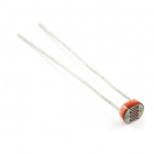
- 1x Light Sensor (From your Arduino 101 SIK)
- 1x 10k Ohm Resistor (From your Arduino 101 SIK)
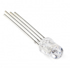
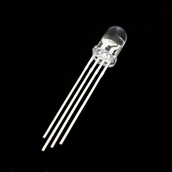
- 1x RGB LED Clear Common Cathode (From your Arduino 101 SIK)
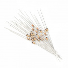
- 3x 100 Ohm Resistors (From your Arduino 101 SIK)
- 9x Jumper Wires (From your Arduino 101 SIK)
Didn't Get the Around-the-Home Expansion Kit?
If you are conducting this experiment and didn't get the Around-the-Home Expansion Kit, we suggest using these parts:


Arduino 101
DEV-13787Suggested Reading
Before continuing with this experiment, we recommend you be familiar with the concepts in the following tutorials:
- Light-Emitting Diodes --- Learn more about LEDs
- Switch Basics --- Learn more about buttons and switches
- Reed Switch Hookup Guide
Introducing the Red Green Blue (RGB) LED
We know that the RGB is probably nothing new to you at this point, but we wanted to give you a bit of a refresher course if it has been awhile.
The Red Green Blue (RGB) LED is three LEDs in one. The RGB has four pins with each of the three shorter pins controlling an individual color: red, green or blue. The longer pin of the RGB is the common ground pin. You can create a custom-colored LED by turning different colors on and off to combine them. For example, if you turn on the red pin and green pin, the RGB will light up as yellow.
But which pin is which color? Pick up the RGB so that the longest pin (common ground) is aligned to the left as shown in the graphic below. The pins are Red, Ground, Green and Blue --- starting from the far left.
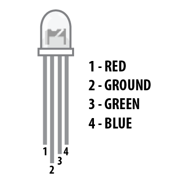
**Note: When wiring the RGB, each colored pin still needs a current-limiting resistor in line with the 101 pin that you plan to use to control it, as with any standard LED. **
Hardware Hookup
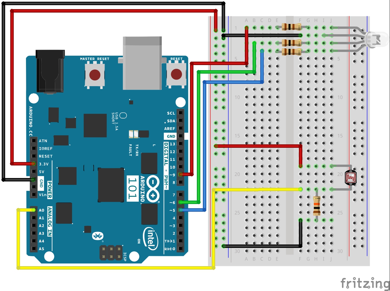
Ready to start hooking everything up? Check out the wiring diagram below to see how everything is connected.
Wiring Diagram for the Experiment
Build Your Blynk App
Start out by building a fresh app in Blynk. Again, your authorization token will be emailed to you; make sure you add it to your Arduino sketch before uploading it!
In this new app, add a zeRGBa widget by clicking the (+) sign in the upper right-hand corner and find the zeRGBa widget from the list.
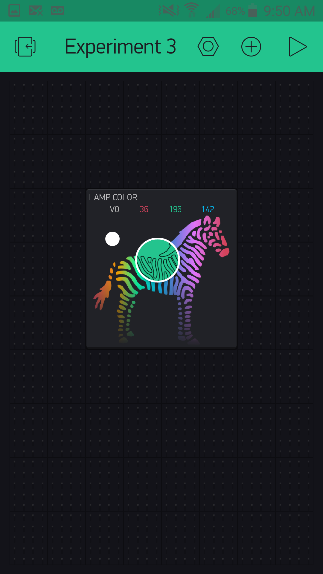
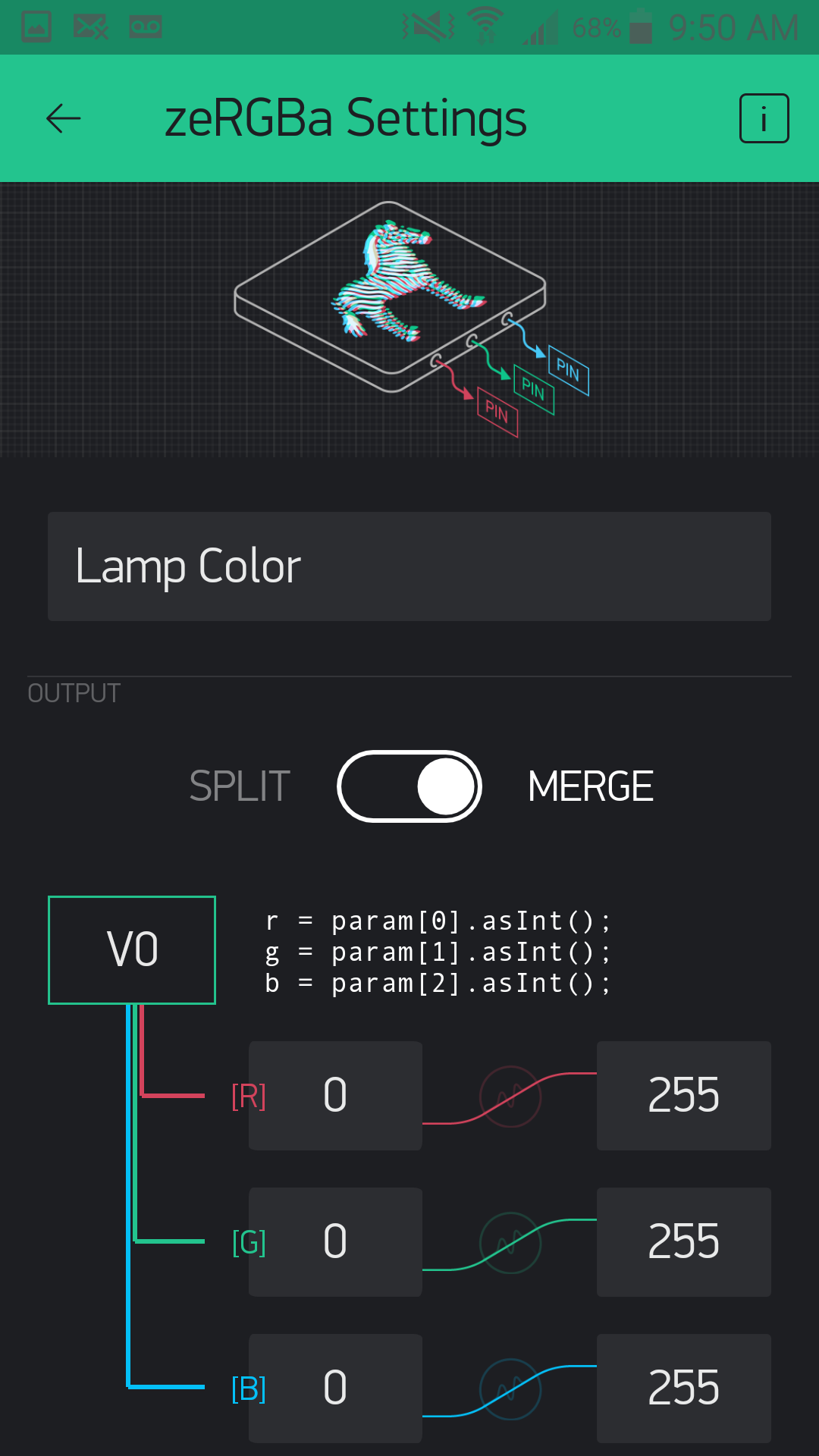
Once you select it and place the widget, open up the settings by pressing once on the widget. Here you can name it like the previous experiment. Finally, set the pin to virtual pin 0 or V0. The zeRGBa widget also has two ways to control pins. You can directly control the pins by using the Split setting and assign each color a pin.
If you are looking to play around with just an RGB and Blynk, this is a fun option to explore later. We want to use the Merge option, which merges the 3 RGB values into an array of values.
From there you add the BLE widget, as you did in Experiment 1. Be sure to have BLE and location turned on to be able to set up and connect to your Arduino 101 board. From there you should be good to go!
Upload Your Sketch
Copy and paste or type out the code below.
Make sure that you add the authorization key from your Blynk app; otherwise this sketch will not work!
language:cpp
/********************************************************************************
SparkFun Around-The-Home SIK Expansion Kit, Experiment 3
SparkFun Electronics
Product URL

Build an RGB night light where you use the Blynk App to configure the color of the RGB when it is lit.

This example is written by: Derek Runberg, Educational Technologist

This sketch was written by SparkFun Electronics, with lots of help from the Arduino community.
This code is completely free for any use.

View circuit diagram and instructions at:https://learn.sparkfun.com/tutorials/around-the-home-expansion-kit

********************************************************************************/

//#define BLYNK_USE_DIRECT_CONNECT

/* Comment this out to disable prints and save space */
#define BLYNK_PRINT Serial


#include <BlynkSimpleCurieBLE.h>
#include <CurieBLE.h>

// You should get Auth Token in the Blynk App.
// Go to the Project Settings (nut icon).
char auth[] = "YOUR AUTH TOKEN";

BLEPeripheral  blePeripheral;

//RGB pin constants
const int RED_PIN = 9;
const int GREEN_PIN = 6;
const int BLUE_PIN = 5;

//sensor pin constant set at A0
const int SENSOR_PIN = A0;

//preset color of the RGB... Red!
int r = 255;
int g = 0;
int b = 0;
int calibrationVal;

void setup()
{
  // Debug console
 Serial.begin(9600);

 delay(1000);

 blePeripheral.setLocalName("Exp_03");
 blePeripheral.setDeviceName("Exp_03");
 blePeripheral.setAppearance(384);

 Blynk.begin(blePeripheral, auth);

 blePeripheral.begin();

 Serial.println("Waiting for connections...");
 calibrationVal = analogRead(SENSOR_PIN);
}

void loop()
{
  int lightVal = analogRead(SENSOR_PIN);
  //if lightVal is less than the calibration value - 50 (it's dark)...
  if (lightVal < calibrationVal - 50) {
    //display set color
    analogWrite(RED_PIN, r);
    analogWrite(GREEN_PIN, g);
    analogWrite(BLUE_PIN, b);
   }
  else {
    //RGB is off
    analogWrite(RED_PIN, 0);
    analogWrite(GREEN_PIN, 0);
    analogWrite(BLUE_PIN, 0);
  }

  blePeripheral.poll();
  Blynk.run();
}

// zeRGBa assigned to V0
BLYNK_WRITE(V0)
{
  // get a RED channel value
  r = param[0].asInt();
  // get a GREEN channel value
  g = param[1].asInt();
  // get a BLUE channel value
  b = param[2].asInt();
}
Code to Note
In this sketch a lot should look pretty familiar to you. We covered the idea of building a light sensor-based night light in the SIK for Arduino 101 Experiment Guide if you would like to see where we started from here.
In this experiment we use the RGB LED instead of a single LED, which should also be somewhat familiar to you. The focus of this experiment is how we set the color and interact with the RGB through Blynk. Here are a few pieces of code that highlight the Blynk functionality.
char auth[] = "YOUR AUTH TOKEN";
We miss this all the time, so you probably do as well. We want to make sure that you are using your authorization token when you upload the sketch, and not just hitting upload. Be sure to change this string to the token Blynk emails to you.
language:cpp
 //preset color of the RGB... Red!
int r = 255;
int g = 0;
int b = 0;
Part of what we are demonstrating with this sketch is making sure that there is enough information in the Arduino sketch for it to function without any input from Blynk from the beginning. With that in mind, we pre-set the RGB color to an intense red (go figure!). The RGB will then stay red until someone connects to the Arduino 101 with Blynk and changes the color. Since these variables are global, when you change the color with the Blynk app, the color will stay the same even when you disconnect the app from the Arduino 101 board.
language:cpp
 // zeRGBa assigned to V0
BLYNK_WRITE(V0)
{
  // get a RED channel value
  r = param[0].asInt();
  // get a GREEN channel value
  g = param[1].asInt();
  // get a BLUE channel value
  b = param[2].asInt();
}
The Blynk API uses event functions. As it polls your Blynk app for changes using the blynk.run() method, it triggers this event function called BLYNK_WRITE(V0) when data is written to virtual pin 0 in Blynk. When you change your zeRGBa widget, it writes an array of values with a red value being the first, a green value the second, and a blue the last. We parse that array of values within the event function and set the global color variables to the appropriate value. We will use this concept later in other experiments as well, so we wanted to be sure to highlight it in detail now.
What You Should See
Now, plug your project in where you would like a night light. At first nothing will happen. Turn the lights in the room off or cover the light sensor. The RGB should turn on with a red color. Now connect to your Arduino 101 board with Blynk and use the zeRGBa to change the color of your RGB.
Now if you turn the lights on, the RGB will turn off. Turn your lights back off, and the RGB should turn back on with the color you picked earlier. As long as you don't unplug the Arduino 101 board, the RGB will stay this color whether you use the Blynk app or not. To change the color, use Blynk!
This experiment may seem a bit simple, but it is here to inspire you to incorporate the parts you already have in your SIK for the Arduino 101 board, as well as to think creatively about how to use Blynk and BLE where it makes sense.
Troubleshooting
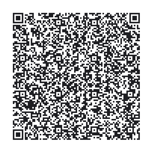
Blynk Shortcut!
If you are having troubles duplicating the functionality above in the Blynk app, scan this QR code with Blynk to get a clone of this experiment!
Program Not Uploading
This happens sometimes; the most likely cause is a confused serial port. You can change this in Tools > Serial Port > and make sure you are using an Arduino 101 board.
Not connecting to the Blynk App
Be sure to check that your Bluetooth is on as well as your location setting. Also make sure your authorization token is correct and in your sketch!
RGB shows wrong colors
Double check your wiring, you may have the wrong color controlled by the wrong pin on the Arduino 101