Smart Home Expansion Kit for Arduino 101
 D___Run___
 Experiment 4: Reading a Door Switch
Introduction
In Experiment 2 you learned how to use a simple reed switch with Blynk and Arduino. In this experiment you will take this a step further and into the world of home security with the magnetic door switch. We will be using Blynk and the Arduino 101 board to arm and disarm your burglar alarm...so watch out, burglars!
Parts Needed
You will need the following parts:
- 1x Breadboard
- 1x Arduino 101 Board
- 1x Magnetic Door Switch
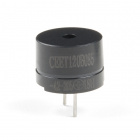
- 1x Buzzer
- 6x Jumper Wires
Didn't Get the Around-the-Home Expansion Kit?
If you are conducting this experiment and didn't get the Around-the-Home Expansion Kit, we suggest using these parts:


Arduino 101
DEV-13787Suggested Reading
Before continuing with this experiment, we recommend you be familiar with the concepts in the following tutorials:
- Light-Emitting Diodes --- Learn more about LEDs
- Switch Basics --- Learn more about buttons and switches
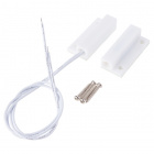
Introducing the Magnetic Door Switch
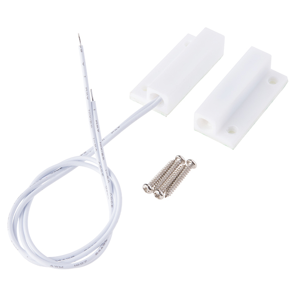
In Experiment 2 you built a circuit containing a reed switch controlled by direct magnet contact: someone placing a magnet on top of the sensor. The door switch included in this kit is roughly the same, but with a specific application in mind as well as wiring added to it so that you can place the sensor a little further away.
The switch assembly has two pieces. When the two halves of the switch assembly are very near each other, or touching, the switch is in one state. Moving the two halves more than 20mm apart from each other will cause the switch to change state. One half contains a magnet, and the other contains a reed switch, a switch that changes state when exposed to a magnetic field.
This type of two-piece switch is often used in home-security systems. One half of the switch is attached to a fixed surface, and the other half to a moving door or window. When the door or window is opened, the two halves are separated from each other, breaking the contact and changing the switch’s state.
Here is a bit of a throwback video description of the door sensor and what it includes for your nostalgic record.
Hardware Hookup
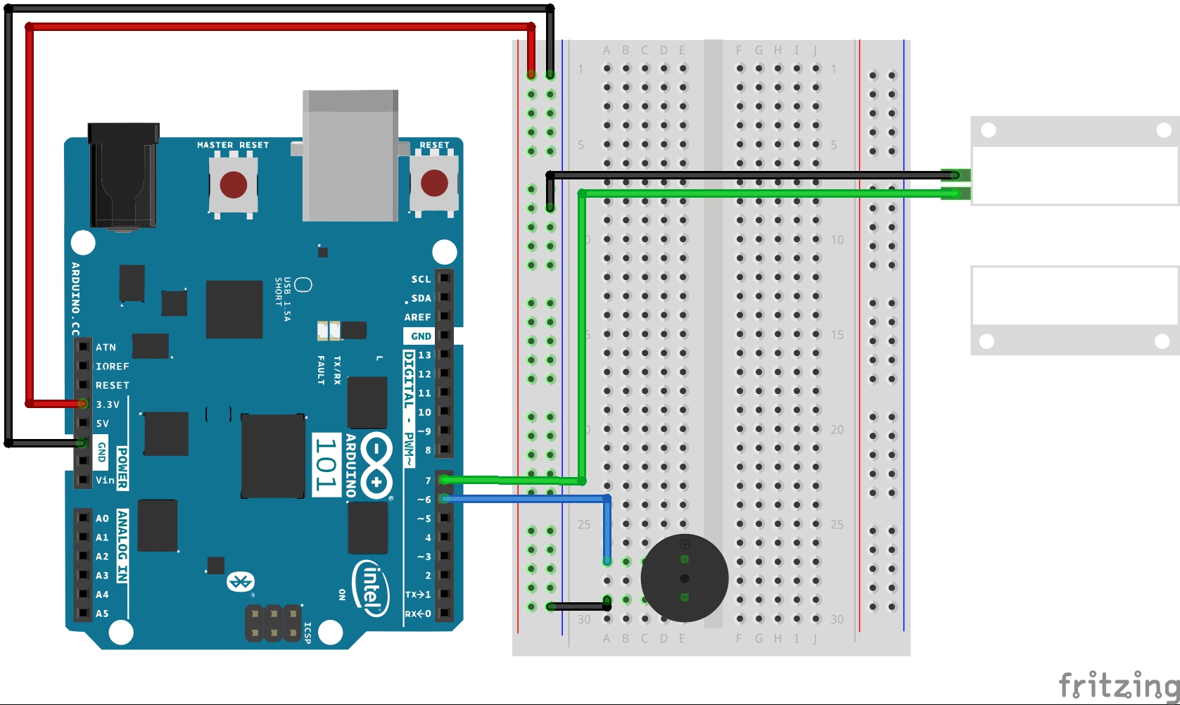
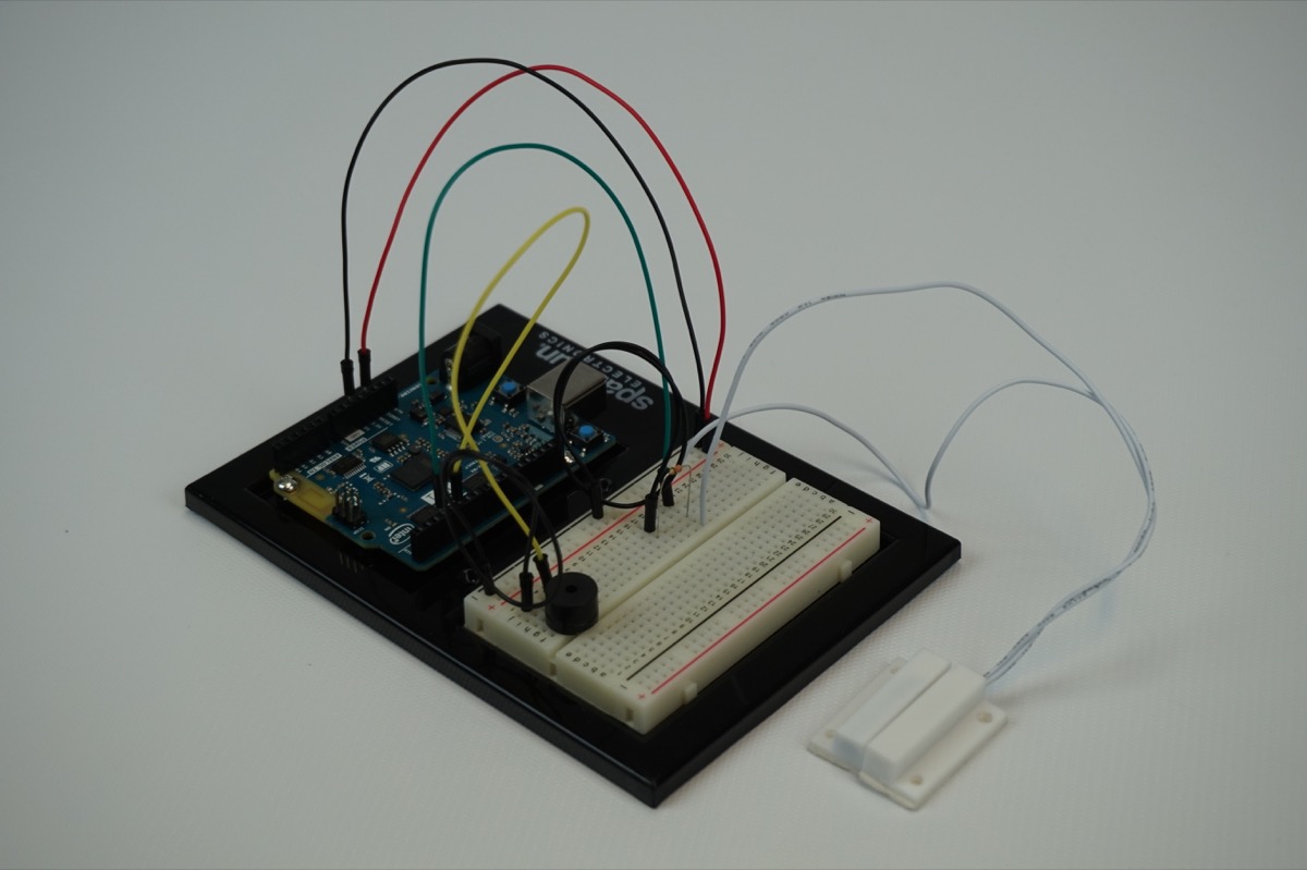
Ready to start hooking everything up? Check out the wiring diagram below to see how everything is connected.
Wiring Diagram for the Experiment
Build Your Blynk App
Your Blynk app will be your way to arm, disarm, silence and check to see if someone has entered through the door and maybe figured out how to disable the buzzer in some way.
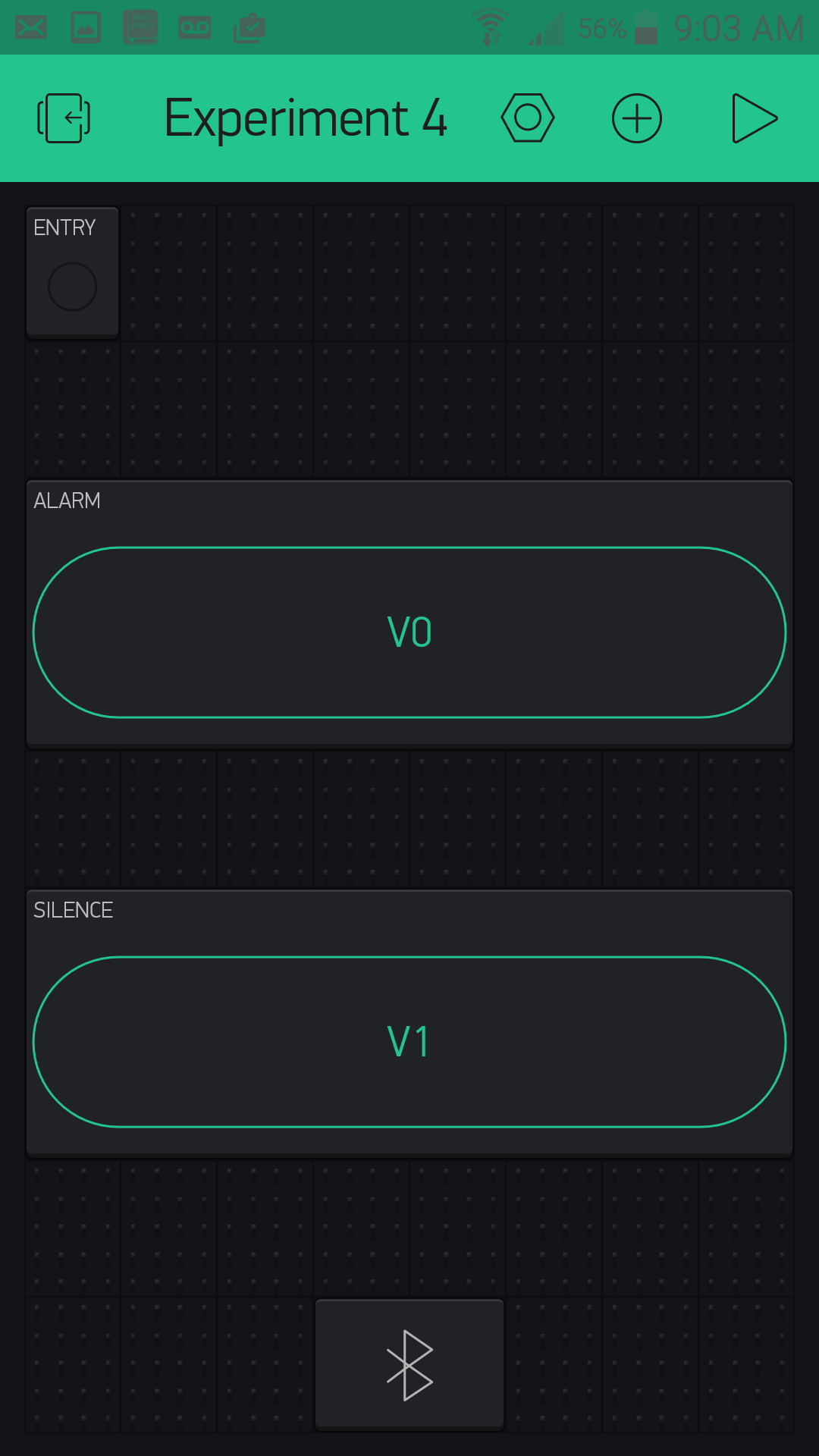
The app consists of two button widgets and an LED widget. One button will control the arming and disarming of the system; the other will be a silencing button to turn the alarm on and off. Finally the LED will be a silent alarm where you can open the app and check to see if someone has entered or not; it will blink if the alarm has been tripped.
To start out, create a new Blynk app and add the BLE widget. Be sure to turn BLE and location on so your phone can connect to the Arduino 101 board using BLE.
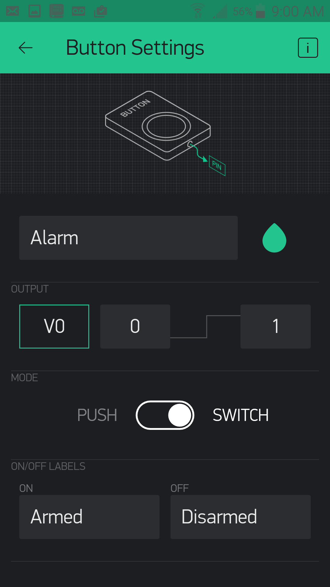
Start out by adding a button. We named it "Alarm" and put it into switch mode. The on and off values are "Armed" and "Disarmed." The pin that the button is connected to is virtual pin 0 or V0.
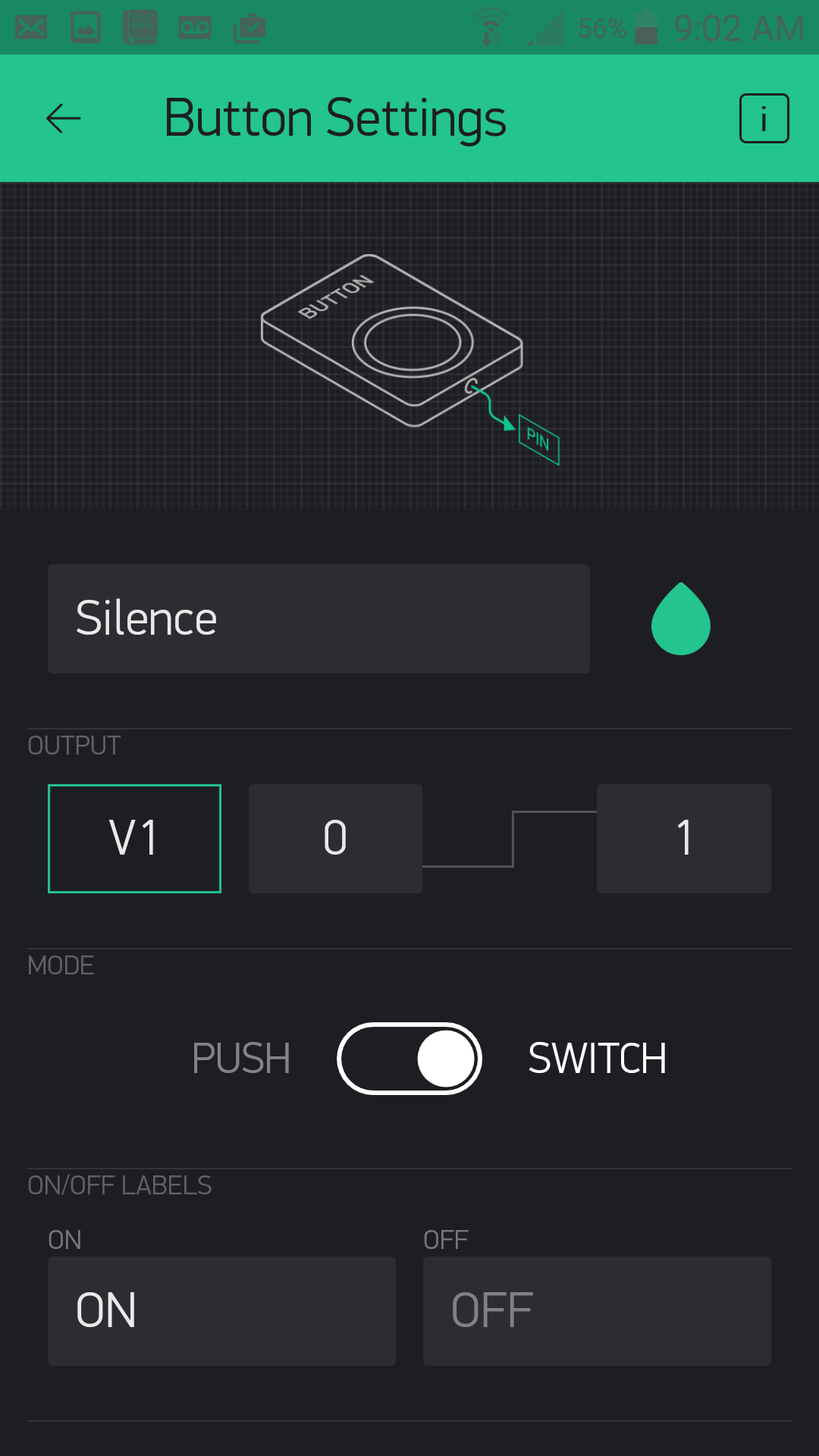
Add another button. This one we named "Silence," which is connected to virtual pin 1 or V1 and also in "switch" mode. We left the on/off labels as they were.
With that, your app should look something like this, maybe with a difference in placement and button colors.
Now, it's time to add the magic on the Arduino 101 end and complete your security system!
Upload Your Sketch
Let's get this code knocked out! Be sure to insert your authorization token into your sketch before you upload it; otherwise your app will not work with this code!
You can type out or copy and paste the following code into the Arduino IDE. Hit upload, and see what happens!
language:cpp
/********************************************************************************
SparkFun Around-The-Home SIK Expansion Kit, Experiment 4
SparkFun Electronics
Product URL

Builds a Blynk app controlled door burglar alarm where you can disarm / arm and mute the alarm from a Blynk app that reads a door switch.

This example is written by: Derek Runberg, Educational Technologist

This sketch was written by SparkFun Electronics, with lots of help from the Arduino community.
This code is completely free for any use.

View circuit diagram and instructions at:https://learn.sparkfun.com/tutorials/around-the-home-expansion-kit

********************************************************************************/

/* Comment this out to disable prints and save space */
#define BLYNK_PRINT Serial
#include <BlynkSimpleCurieBLE.h>
#include <CurieBLE.h>

BLEPeripheral  blePeripheral;


// You should get Auth Token in the Blynk App.
// Go to the Project Settings (nut icon).
char auth[] = "your auth token";

//create global constant for component pins
const int SENSOR_PIN = 7;
const int BUZZER_PIN = 6;

//create boolean variables for mute and armed options
boolean mute = false;
boolean armed = false;


void setup()
{
  Serial.begin(9600);
  blePeripheral.setLocalName("Exp_04");
  blePeripheral.setDeviceName("Exp_04");
  blePeripheral.setAppearance(384);

  Blynk.begin(blePeripheral, auth);

  blePeripheral.begin();

  //set BUZZER_PIN as OUTPUT for the buzzer
  pinMode(BUZZER_PIN, OUTPUT);
  //set SENSOR_PIN as INPUT_PULLUP for the door switch
  pinMode(SENSOR_PIN,INPUT_PULLUP);
}

void loop()
{
  int doorState = digitalRead(SENSOR_PIN);
  if(armed == true && doorState == 1){
    if(mute == true){
       noTone(BUZZER_PIN);
    }else{
      tone(BUZZER_PIN, 5000);
    }
  }
  else{
    noTone(BUZZER_PIN);
  }
  Blynk.run();
  blePeripheral.poll();
}

BLYNK_WRITE(V0)
{
  armed = !armed;
}

BLYNK_WRITE(V1)
{
  mute = !mute;
}
Code to Note
pinMode(SENSOR_PIN,INPUT_PULLUP);
To keep the wiring simple and not use a pullup resistor we used the INPUT_PULLUP constant as the pinMode. This internally pulls the pin high and removes the need for the resistor, but then causes the boolean logic of the door switch being open vs. closed.
language:cpp
BLYNK_WRITE(V0)
{
  armed = !armed;
}

BLYNK_WRITE(V1)
{
  mute = !mute;
}
We use two Blynk event functions that are connected to the app via the arm / disarm button and the mute button. We use those events to do nothing but toggle global variables of mute and armed. That way you can arm / disarm and mute the alarm system then disconnect the app and the system will function on its own and not rely on the connection of the app for any real time control.
int doorState = digitalRead(SENSOR_PIN);
We store the state of the door (opened = 1, closed=0) in a local variable called doorState using a simple digitalRead() function.
language:cpp
if(armed == true && doorState == 1){
    if(mute == true){
       noTone(BUZZER_PIN);
    }else{
      tone(BUZZER_PIN, 5000);
    }
  }
We use nested if statements to check the state of the door. If it is close and muted the buzzer is quiet. Else the buzzer sounds using the tone() command at 5000 Hz!
What You Should See
You should power up the circuit with the door switch mounted to the door, or whatever you are securing (cabinet, box, etc.). Make sure the door is closed and connect to your project through Blynk. When you open the app and run it, you should be able to arm the alarm and also set whether the alarm is silent or not. Leave it off for testing. Now, open the door. The alarm should go off, and the LED in your Blynk app should be blinking! You should be able to silence it from the Blynk app, as well as disarm the lock.
The great thing about this system is that when you manipulate the settings using the Blynk widgets your options are saved as variables on the Arduino 101 board, so you should be able to set the alarm and walk away.
Troubleshooting
Blynk Shortcut
If you are having troubles duplicating the functionality above in the Blynk app, scan this QR code with Blynk to get a clone of this experiment!
Buzzer not buzzing
Double check your wiring to the buzzer. It is a polarized port and you may have it backwards, or the wires in your breadboard may not be aligned correctly.
Cannot toggle armed vs. disarmed
Make sure you are connected via BLE to your project and it shows up in your app. The Blynk app is the only way to disarm or mute the alarm system.