Smart Home Expansion Kit for Arduino 101
 D___Run___
 Experiment 2: Using a Reed Switch
Introduction
Detecting the presence of an object is always tough. If you base it off of weight, you always run the risk of someone placing something on your sensor or even just leaning on it. Then there are other, more complicated means that can also produce false positives or negatives.
Enter the reed switch! A reed switch is a simple switch that is triggered by a magnet, so unless you have a lot of magnets sitting around, it gives you an easy way to detect a specific object by simply adding a magnet to it. You can then place the reed switch circuit under a table, under a bowl or plate or even under a drawer to detect if the drawer is opened or closed if you have a powerful enough magnet.
This experiment will build on Experiment 1 where you controlled the IoT Relay with a button in Blynk. You will build an app in Blynk that will help you find your keys by having an indicator LED in the Blynk app turn on if your keys are in a bowl strategically placed by your front door!
Parts Needed
You will need the following parts:
- 1x Breadboard (From your Arduino 101 SIK)
- 1x Arduino 101 Board (From your Arduino 101 SIK)
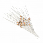
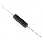
- 1x Reed Switch
- 2x Jumper Wires (From your Arduino 101 SIK)
- 1x 10k Ohm Resistor (From your Arduino 101 SIK)
- 1x Magnet Ring - 3/16"
Didn't Get the Around-the-Home Expansion Kit?
If you are conducting this experiment and didn't get the Around-the-Home Expansion Kit, we suggest using these parts:


Arduino 101
DEV-13787Suggested Reading
Before continuing with this experiment, we recommend you be familiar with the concepts in the following tutorials:
- Light-Emitting Diodes --- Learn more about LEDs
- Switch Basics --- Learn more about buttons and switches
- Reed Switch Hookup Guide
Introducing the Reed Switch
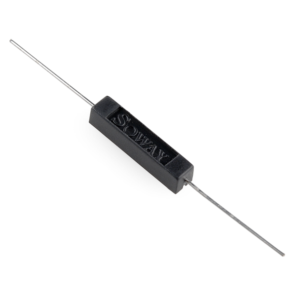
Reed switches are magnetically actuated electrical switches (not magically actuated, though it seems that way sometimes). When the body of the switch is exposed to a magnetic field --- like a magnet or even a strong electrical current --- two ferrous materials inside pull together, the connection closes, and current can flow. In the absence of a magnetic field, the switch opens, as does the circuit it’s a part of.
There are all sorts of creative applications for reed switches. They’re perfect for any projects that require non-contact control. A magnetic door switch, for example, is just a dressed-up reed switch and a mating magnet. By keeping both parts of the switch separate, the door can open and close freely (and maintain its regular duties as a door). The anemometer in our weather meter combines a number of reed switches, which all open and close in order as the wind blows; count the time between switch closures to determine the wind speed.
Here is a quick demonstration of a simple circuit that uses a reed switch to control an LED circuit.
Hardware Hookup
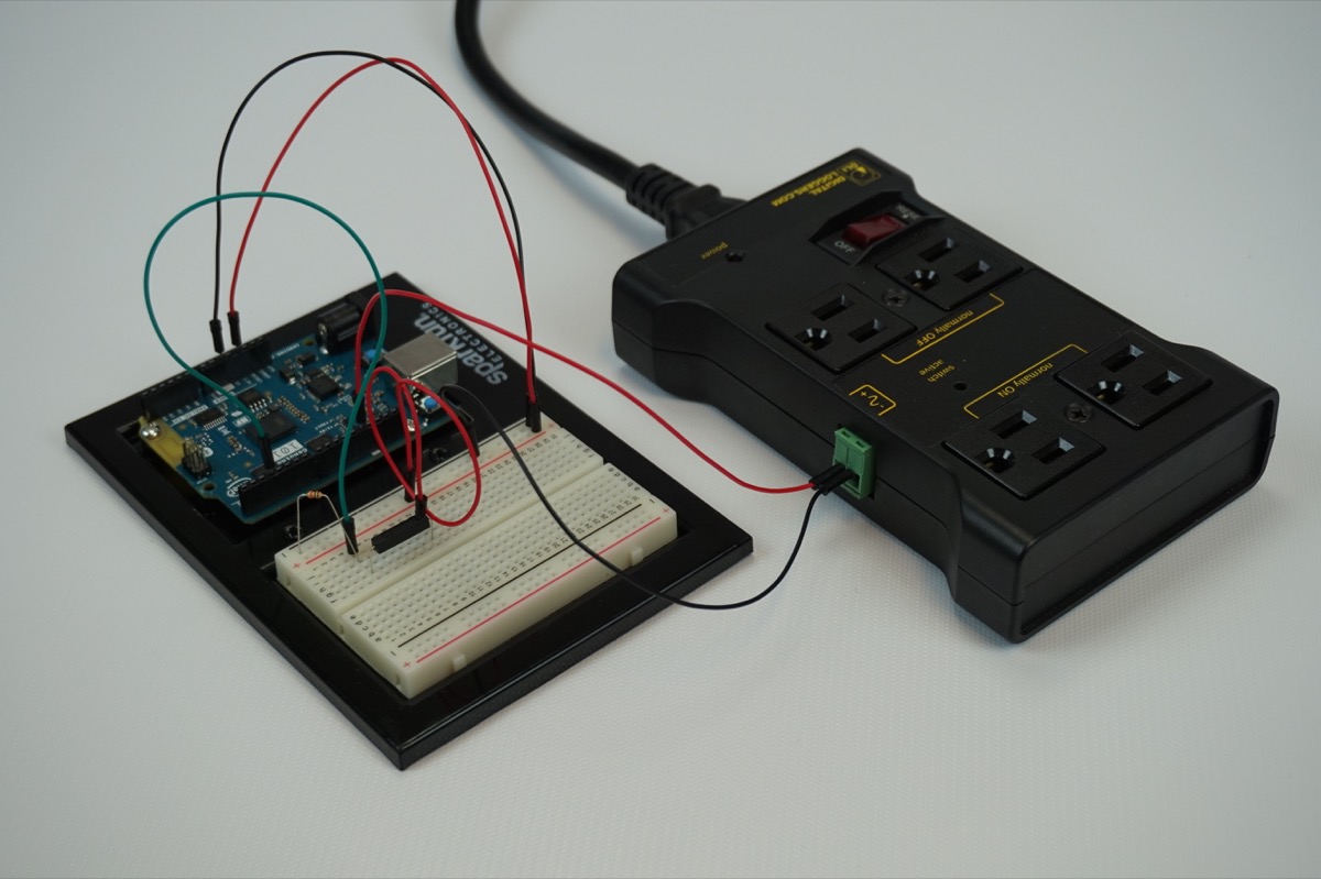
Ready to start hooking everything up? Check out the wiring diagram below to see how everything is connected.
Wiring Diagram for the Experiment

Build Your Blynk App
Start out by building a fresh app in Blynk. Again, your authorization token will be emailed to you; make sure you add it to your Arduino sketch before uploading it!
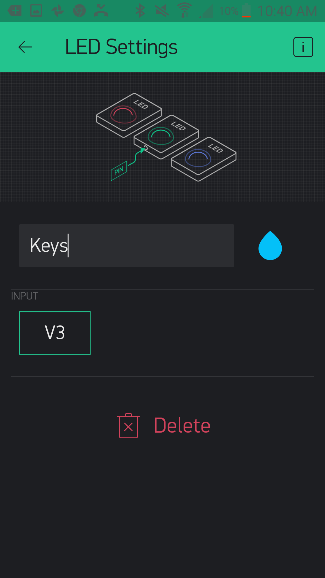
In this new app add an LED widget by clicking the (+) sign in the upper right-hand corner and find the LED widget from the list.
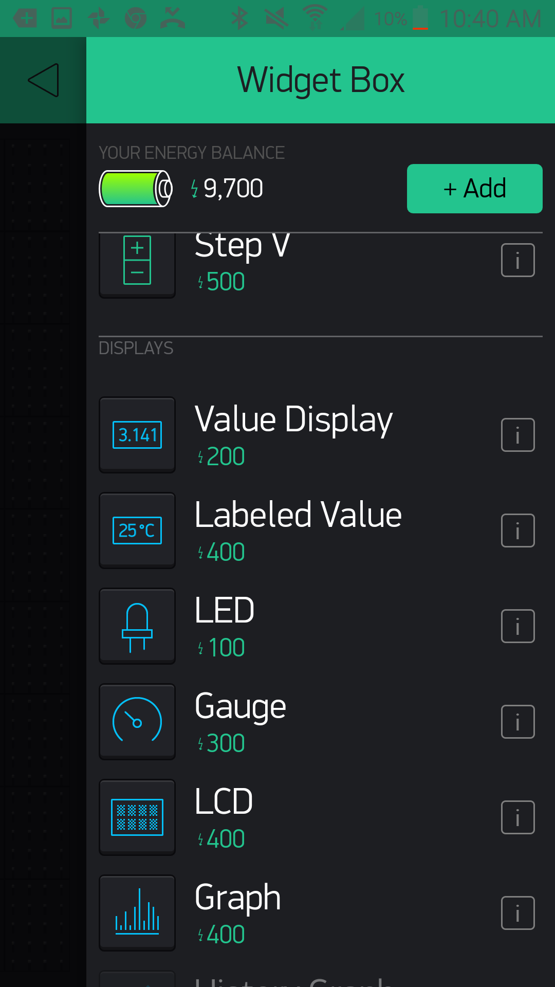
Once you select it and place the widget, open up the settings by pressing once on the widget. Here you can name it as in the previous experiment, and if you want to change the color, you can do so by clicking the teardrop logo next to the name. Finally, set the pin to virtual pin 3 or V3. Notice that the LED widget only accepts virtual pin numbers, which means that if you want to use this widget you need to follow this experiment's example of turning the widget on and off from your Arduino 101 board.
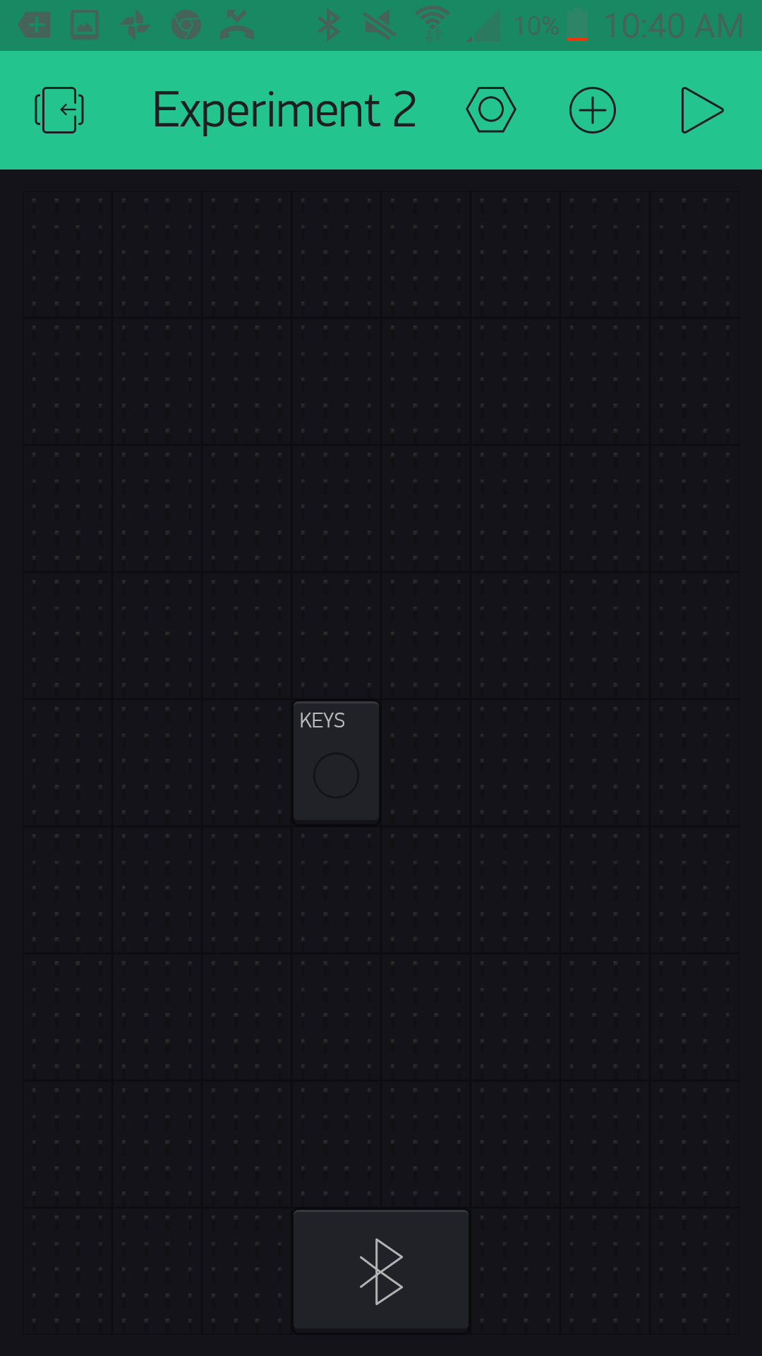
From there you add the BLE widget, as you did in Experiment 1. Be sure to have BLE and location turned on to be able to set up and connect to your Arduino 101 board. From there you should be good to go!
Upload Your Sketch
You will be adding to the example Arduino 101 BLE sketch we used in Experiment 1. Feel free to open that in Arduino by navigating to File > Examples > Blynk > Bluetooth >Arduino_101_BLE or copy and paste the code below.
Make sure you add the authorization key from your Blynk app; otherwise this sketch will not work!
language:cpp
/********************************************************************************
SparkFun Around-The-Home SIK Expansion Kit, Experiment w
SparkFun Electronics
Product URL

Detects the presence of an object attached to a magnet with a reed switch. If a magnet is present it turns on an LED widget in a Blynk app.

This example is written by: Derek Runberg, Educational Technologist

This sketch was written by SparkFun Electronics, with lots of help from the Arduino community.

This code is completely free for any use.

View circuit diagram and instructions at:https://learn.sparkfun.com/tutorials/around-the-home-expansion-kit

********************************************************************************/

/* Comment this out to disable prints and save space */
#define BLYNK_PRINT Serial

#include <BlynkSimpleCurieBLE.h>
#include <CurieBLE.h>


// You should get Auth Token in the Blynk App.
// Go to the Project Settings (nut icon).
char auth[] = "YOUR_AUTH_TOKEN";

// Select your pin with physical button
const int REED_SWITCH = 3;

WidgetLED led3(V3);

BlynkTimer timer;
BLEPeripheral  blePeripheral;

// V3 LED Widget represents the physical button state
boolean reedState = false;
//LED on pin 13
const int LED_PIN = 13;

void setup()
{
  // Debug console
  Serial.begin(9600);

  //give your project a local and device name
 blePeripheral.setLocalName("Exp_02");
 blePeripheral.setDeviceName("Exp_02");
 //set the BLE appearance
 blePeripheral.setAppearance(384);

 //start Blynk
 Blynk.begin(blePeripheral, auth);

 //start the BLE service
 blePeripheral.begin();
  // Setup physical button pin (active low)
  pinMode(REED_SWITCH, INPUT);
  //set LED_PIN as output
  pinMode(LED_PIN,OUTPUT);

  timer.setInterval(100L, checkState);
}

void loop()
{
  Blynk.run();
  blePeripheral.poll();
  timer.run();
}

void checkState()
{
  // Read switch
  boolean isPressed = (digitalRead(REED_SWITCH) == HIGH);

  // If state has changed...
  if (isPressed != reedState) {
    if (isPressed == HIGH) {
      led3.on();
      digitalWrite(LED_PIN,HIGH);
    } else {
      led3.off();
      digitalWrite(LED_PIN,LOW);
    }
    reedState = isPressed;
  }
}
Code to Note
In this example we read the reed switch and, depending on its state, we turn the LED widget in the app on or off.
BlynkTimer timer;
The lessons learned here are that you can create a widget object in your Arduino sketch and control it via code. Also, the idea of a timer is important here. If we placed all of our code into the loop() Arduino and Blynk would throw overflow errors. We can only send so much data to our Blynk app before it gets overwhelmed. So, we use the BlynkTimer object to set a time interval for a custom function --- in this case, check the state of the reed switch and toggle the LedWidget depending on that value.
const int REEDSWITCH = 3;
In this sketch we store the pin number that the reed switch is connected to as a global constant integer. We do this so we can easily change the pin number in one place at the top of the sketch, but also so the pin number cannot be changed in code for any reason. This is safe programming practice that we will employ throughout this set of experiments.
WidgetLED led(V3);
The Blynk library for Arduino doesn't use the conventional setup and use for pins using the Arduino language. Instead, it uses object notation! So, to create an LED widget you define an object of WidgetLED (we called ours "led") and then pass it the virtual Blynk pin that you would like to assign to it --- in this case v3, or virtual pin 3.
boolean isPressed = (digitalRead(REED_SWITCH) == LOW);
Inside of the custom function we create a local Boolean variable called isPressed and store the state we get from the logical statement on the reed switch. If a magnet is present, this value will be true; if it is absent, the value will be false.
language:cpp
  // If state has changed...
  if (isPressed != reedState) {
    if (isPressed == true) {
      led3.on();
    } else {
      led3.off();
    }
    reedState = isPressed;
  }
We finally use an if() statement to control the LED widget. If the isPressed variable is equal to true the LED widget will turn on. If the state variable is false the widget will be off.
Notice that there is a bit of a delay between removing the magnet and the LED widget toggling. This is due to a bit of latency built up between the BLE polling and the timer. In this application this works because we are looking for the presence of something that doesn't move that often.
What You Should See
When you hold a magnet close to the reed switch, the LED on connected to pin 13 on the Arduino 101 should turn on, and the LED widget in your app should also turn on. When the magnet is removed, the LED and the widget indicator should turn off.
A great application for this circuit would be to find a bowl for your keys and insert this circuit in the base. Hook up the IoT Relay to pin 13 on the Arduino 101 as shown in Experiment 1. Then, place the magnet on your key chain. When you get home late at night, all you need to do is throw your keys into your newly built bowl, and a lamp plugged into the IoT Relay will turn on. When you are in a rush to leave and can't find your keys, you can check to see if they are where they should be or not. When you take the keys from the bowl, the lamp turns off as you leave.
The great thing about this small experiment is that it highlights that not everything has to be connected to Blynk or Arduino in order for the two functions to work. You can use Blynk or not, and it doesn't get in the way of the Arduino sketch!
This experiment may seem overly simple, but it is here as something for you to build off of. Add other sensors and LED widgets to create indicators for different states of a project. Blynk has almost infinite virtual pins, so you are limited only by the number of LED widgets you can fit on your screen!
Troubleshooting
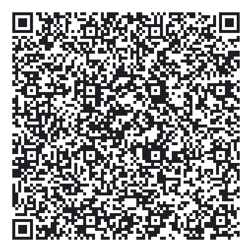
Blynk Shortcut!
If you are having troubles duplicating the functionality above in the Blynk app, scan this QR code with Blynk to get a clone of this experiment!
Program Not Uploading
This happens sometimes; the most likely cause is a confused serial port. You can change this in Tools > Serial Port > and make sure you are using an Arduino 101 board.
Not Connecting to the Blynk App
Be sure to check that your Bluetooth is on. Also make sure your authorization token is correct and in your sketch!
Still No Success
A broken circuit is no fun. Send us an email, and we will get back to you as soon as we can: techsupport@sparkfun.com