Smart Home Expansion Kit for Arduino 101
 D___Run___
 Experiment 5: Motion!
Introduction
OK, so you have detected the presence of an object, built a door security system, but what about detecting motion, the number one way we detect people? Enter the PIR (Passive Infrared) motion sensor! In this experiment you will look at how to use the PIR motion sensor to detect, well...motion. We will then put it to an interesting use other than to see whether something is moving or not.
The application of this sensor will be to build a pretty cool and colorful locking/latching system for a cabinet using the PIR motion sensor and an RGB with a servo from your Arduino 101 SIK with Blynk. Ready to go nuts? Yeah, we thought so!
Parts Needed
You will need the following parts:
- 1x Breadboard (From your Arduino 101 SIK)
- 1x Arduino 101 Board (From your Arduino 101 SIK)
- 1x PIR Motion Sensor
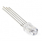
- 1x RGB LED Clear Common Cathode (From your Arduino 101 SIK)
- 3x 100 Ohm Resistor (From your Arduino 101 SIK)
- 14x Jumper Wires (From your Arduino 101 SIK)
- 1x Servo Motor (From your Arduino 101 SIK)
Didn't Get the Around-the-Home Expansion Kit?
If you are conducting this experiment and didn't get the Around-the-Home Expansion Kit, we suggest using these parts:


Arduino 101
DEV-13787Suggested Reading
Before continuing with this experiment, we recommend you be familiar with the concepts in the following tutorials:
- Light-Emitting Diodes --- Learn more about LEDs
- Switch Basics --- Learn more about buttons and switches
- Hobby Servo Tutorial --- Learn more about Servo motors
- PIR Motion Sensor Hookup Guide --- Take a deeper dive into the background of the PIR Motion Sensor
Introducing the PIR Motion Sensor
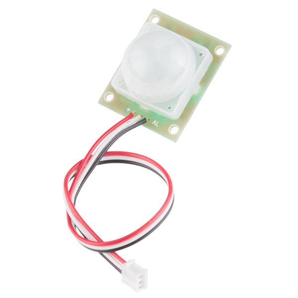
Passive infrared sensors are motion-detecting devices used in security systems across the world --- even though you may not see them, they probably see you!
Using the PIR sensor is simple: power it up, connect a pull-up resistor to the open-collector signal pin, and watch for it to go low. The PIR can sense abrupt changes in scenery as far as 10 feet (~3m) away. Once your microcontroller is sensing movement, it can trigger a buzzer, text message, tweet or klaxon.
Take a look at this Simple Circuit video to see the PIR Motion Sensor in action!
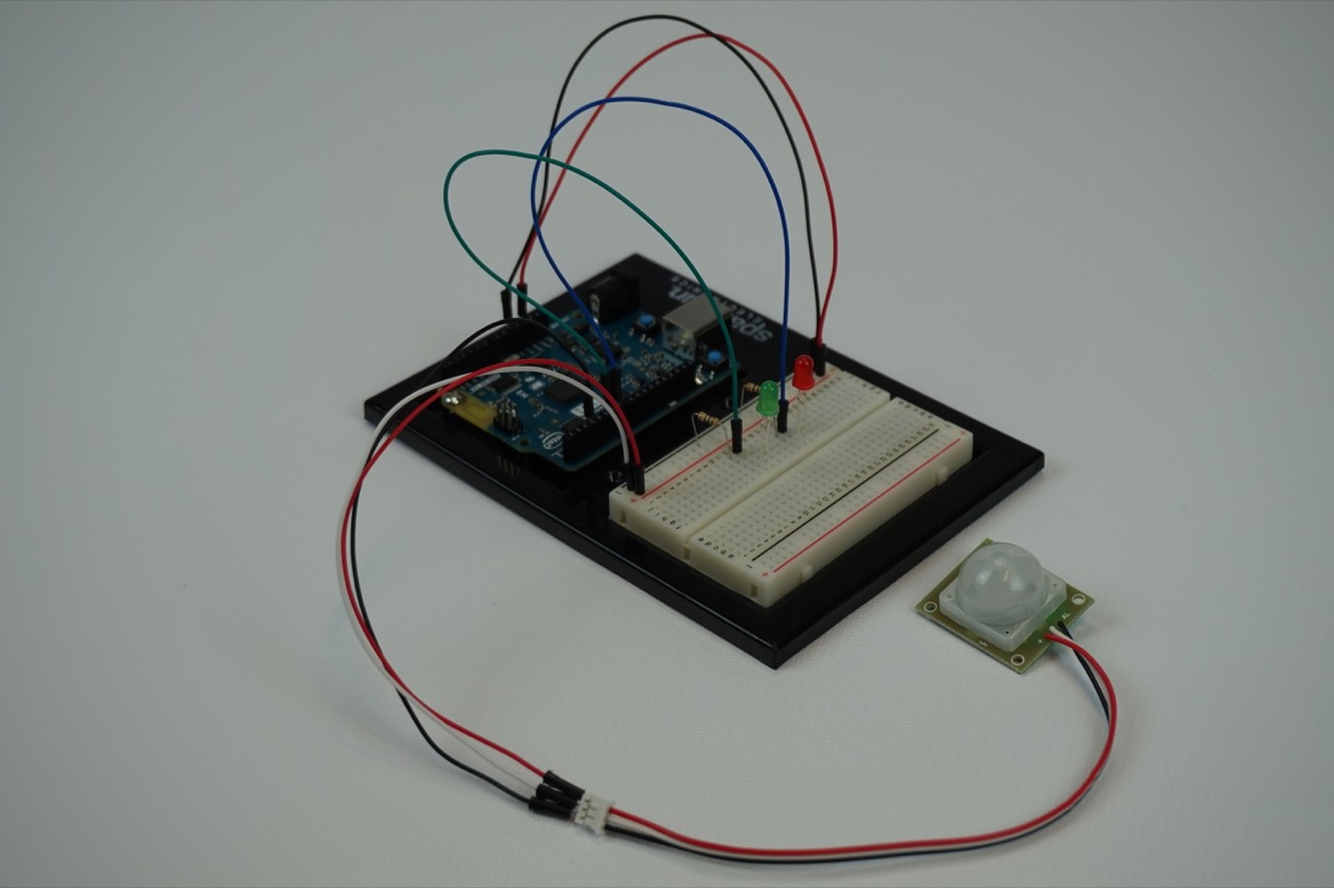
Hardware Hookup
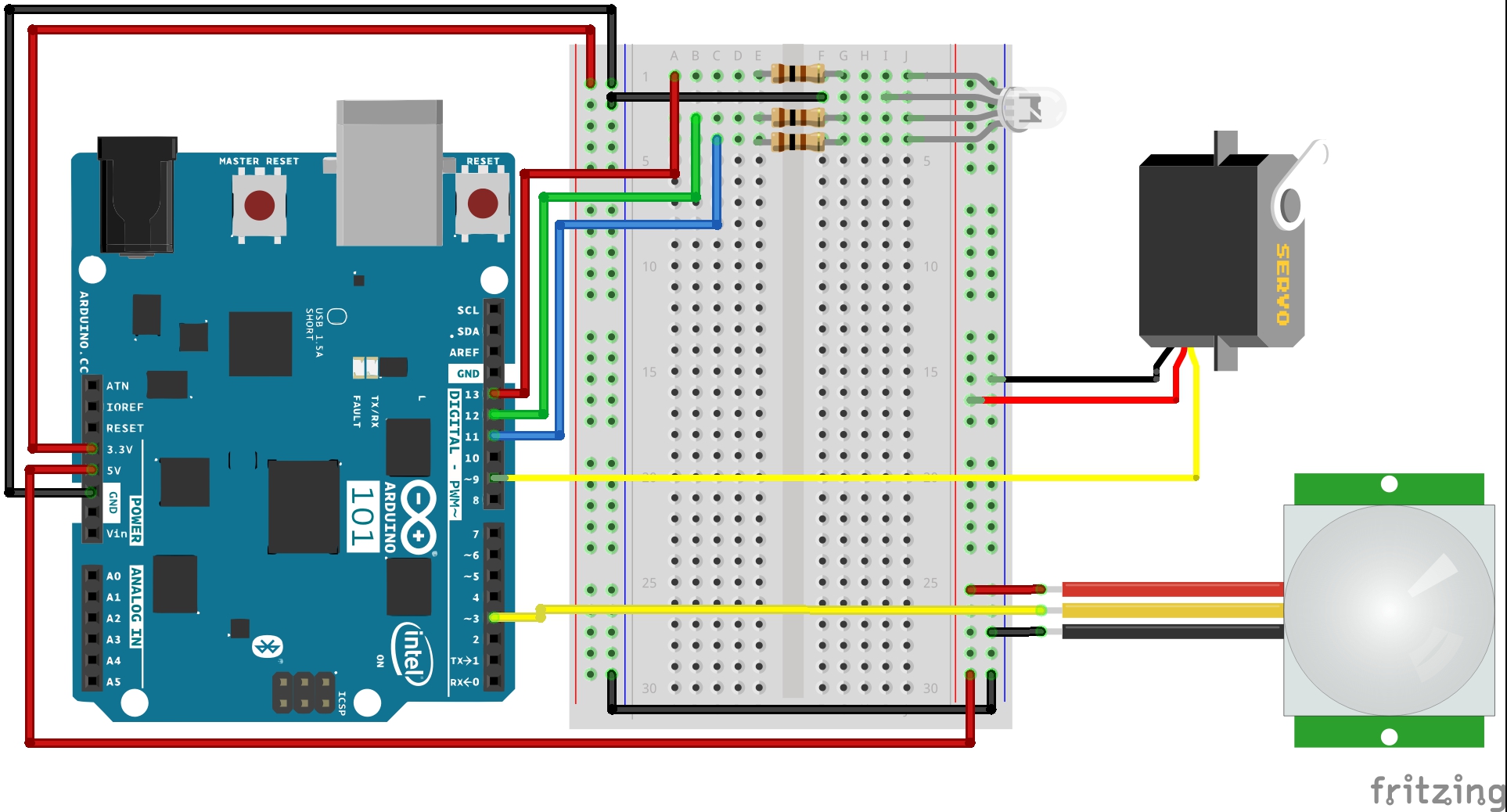
Ready to start hooking everything up? Check out the wiring diagram below to see how everything is connected.
Wiring Diagram for the Experiment
Build Your Blynk App
The Blynk app half of this project should be pretty straightforward for you. Again, be sure to create a new app in Blynk and check your email for the authorization token for your sketch.
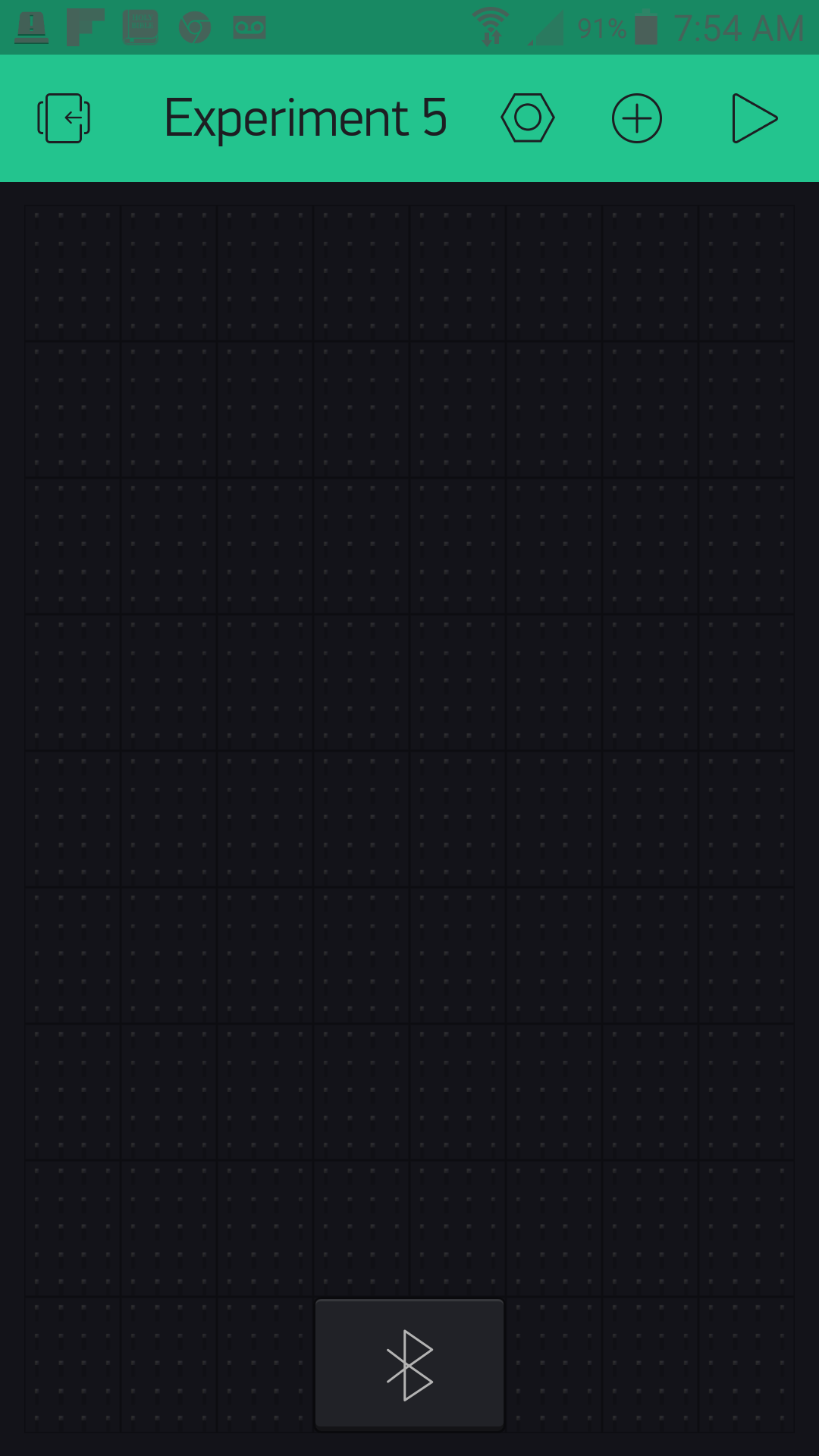
As with all of the Blynk apps that use the Arduino 101 board, add the BLE widget and open the settings to connect your phone to the board.
Once you have added the BLE widget, all you need to do is add three button widgets to your app and place/resize them to your taste.
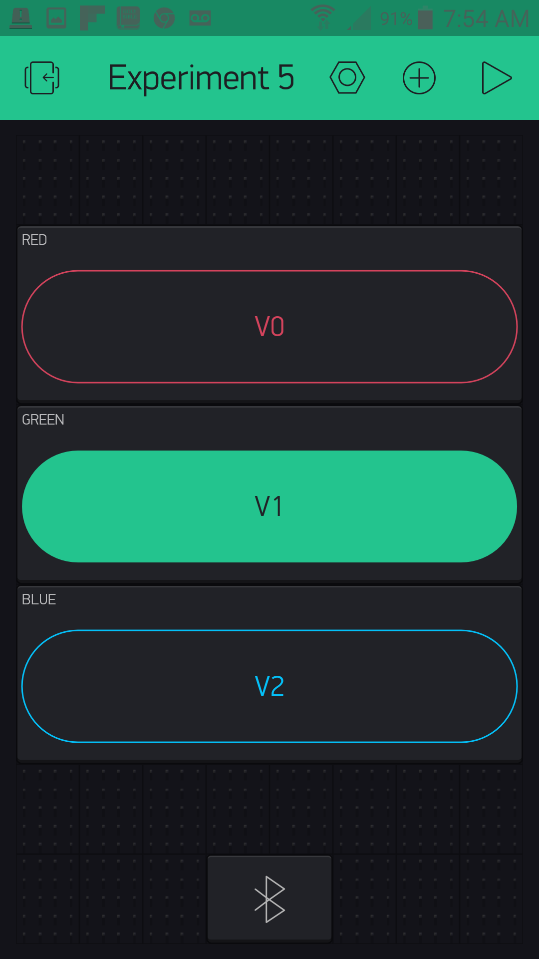
Each button will correspond to a color that you will see from the RGB LED (RED, GREEN and BLUE). We labeled each one accordingly and changed its color to match its name.
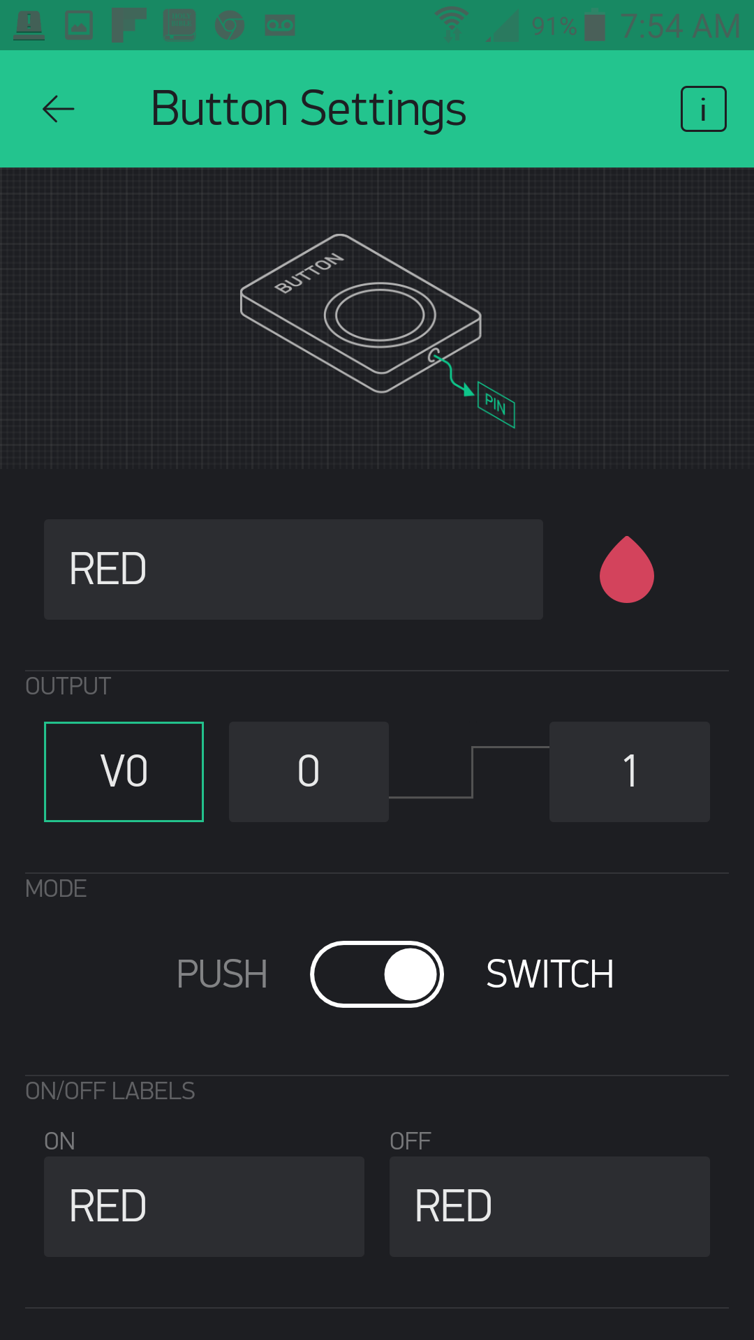
We then assigned each color a virtual pin to control. Here is what we used:
RED => Virtual Pin 0
GREEN => Virtual Pin 1
BLUE => Virtual Pin 2
The final task in setup of the buttons is to change each one to switch mode. This will keep the event from being triggered when you release the button and giving you a false value.
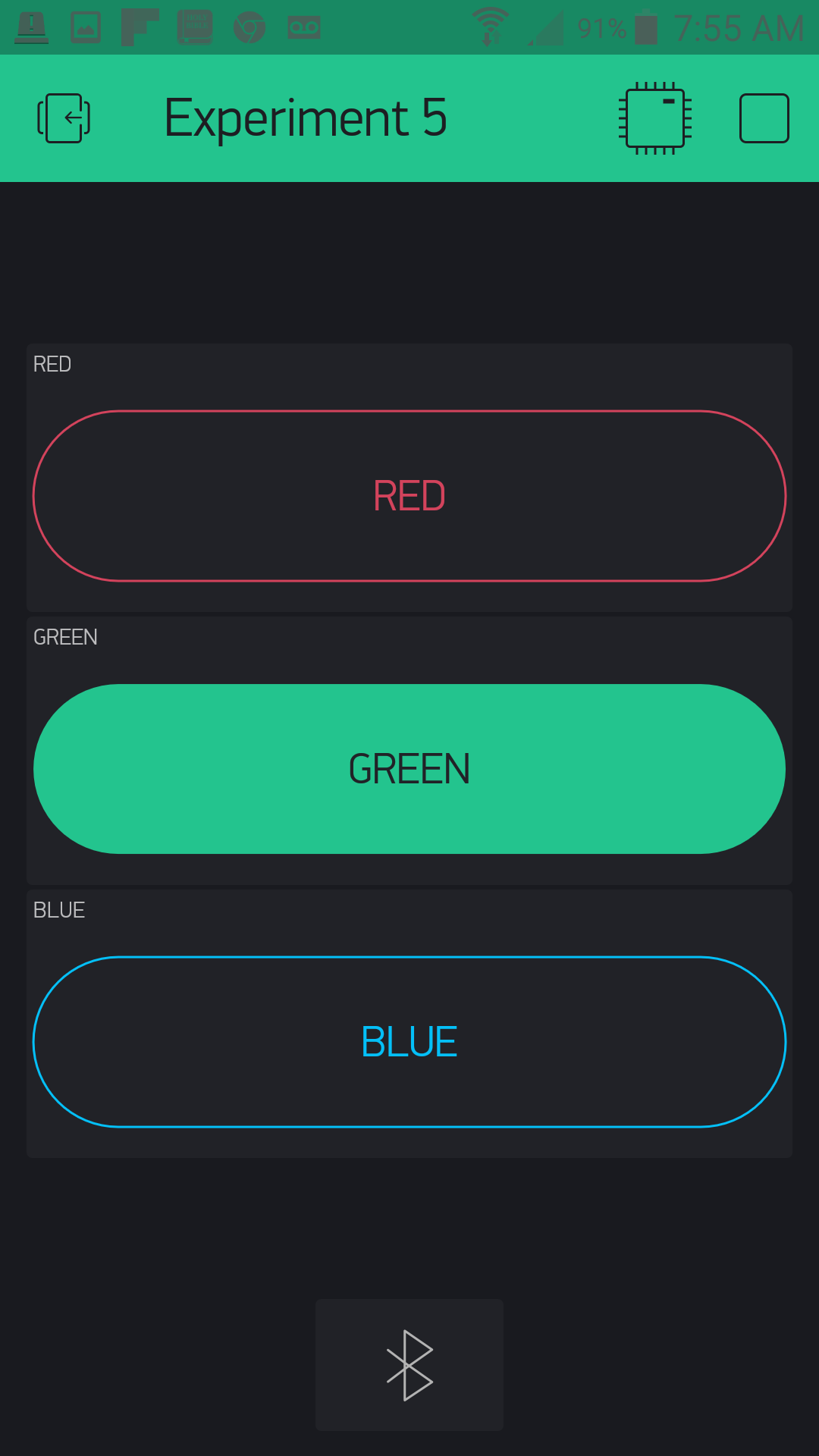
Here is what your completed RGB door key app should look like:
Uploading Your Sketch
Open the Arduino IDE software on your computer. Coding in the Arduino language will control your circuit.
You can type out or copy and paste the following code into the Arduino IDE. Hit upload, and see what happens!
language:cpp
/********************************************************************************
SparkFun Around-The-Home SIK Expansion Kit, Experiment 5
SparkFun Electronics
Product URL

Build a combination lock that detects when someone is present then displays a color on an RGB LED. The user has to input the color into a Blynk app to open a servo controlled latch.

This example is written by: Derek Runberg, Educational Technologist

This sketch was written by SparkFun Electronics, with lots of help from the Arduino community.
This code is completely free for any use.

View circuit diagram and instructions at:https://learn.sparkfun.com/tutorials/around-the-home-expansion-kit

********************************************************************************/

/* Comment this out to disable prints and save space */
#define BLYNK_PRINT Serial
#include <BlynkSimpleCurieBLE.h>
#include <CurieBLE.h>
#include <Servo.h>

Servo doorLatch;
BLEPeripheral  blePeripheral;


// You should get Auth Token in the Blynk App.
// Go to the Project Settings (nut icon).
char auth[] = "YOUR_AUTH_TOKEN";

const int RED_PIN = 13;
const int GREEN_PIN = 12;
const int BLUE_PIN  = 11;

const int MOTION_PIN = 3;
const int SERVO_PIN = 9;

int keyValue = 0;
int show;
boolean motion = false;

void setup()
 {
  Serial.begin(9600);
  blePeripheral.setLocalName("Exp_05");
  blePeripheral.setDeviceName("Exp_05");
  blePeripheral.setAppearance(384);

  Blynk.begin(blePeripheral, auth);

  blePeripheral.begin();

  // Set RGB LED pins as OUTPUT
  pinMode(13, OUTPUT);
  pinMode(12, OUTPUT);
  pinMode(11, OUTPUT);

  //set MOTION_PIN as INTPUT_PULLUP for motion sensor
  pinMode(MOTION_PIN, INPUT_PULLUP);

  //attach servo to SERVO_PIN
  doorLatch.attach(SERVO_PIN);

  //attach the interrupt to the motion pin
  attachInterrupt(MOTION_PIN, trigger, FALLING);
  doorLatch.write(10);
}

void loop()
{
  blePeripheral.poll();
  Blynk.run();

  if(motion == true){
    show = random(11,14);
    digitalWrite(show,HIGH);
    Serial.println(show);
    motion = !motion;
  }
}

//custom function called trigger
void trigger() {
  motion = !motion;
  detachInterrupt(MOTION_PIN);
}

BLYNK_WRITE(V0)
{
  keyValue = 0 + param.asInt(); // Get value as integer
  if (keyValue + show == 14) {
    doorLatch.write(90);
    digitalWrite(show, LOW);
    Serial.println("latch open");
    attachInterrupt(MOTION_PIN, trigger, FALLING);
  }
  else {
    keyValue = 0;
    doorLatch.write(10);
    Serial.println("latch closed");
  }
}

BLYNK_WRITE(V1)
{
  keyValue = 1 + param.asInt(); // Get value as integer
  if (keyValue + show == 14) {
    doorLatch.write(90);
    digitalWrite(show, LOW);
    Serial.println("latch open");
    attachInterrupt(MOTION_PIN, trigger, FALLING);
  }
  else {
    keyValue = 0;
    doorLatch.write(10);
    Serial.println("latch closed");
  }
}

BLYNK_WRITE(V2)
{
  keyValue = 2 + param.asInt(); // Get value as integer
  if (keyValue + show == 14) {
    doorLatch.write(90);
    digitalWrite(show, LOW);
    Serial.println("latch open");
    attachInterrupt(MOTION_PIN, trigger, FALLING);
  }
  else {
    keyValue = 0;
    doorLatch.write(10);
    Serial.println("latch closed");
  }
}
Code to Note
This Experiment uses a bunch of hardware from both the Expansion Kit and the SIK for the Arduino 101, and also presents a number of programming concepts to dive into using both Blynk and Arduino. Hope you have your programming hat on because here we go!
language:cpp
int keyValue = 0;
int show;
Most of the top half of the sketch you have seen before: setup of Blynk and the BLE setup. But, we create two global variables: one called keyVale, which we assign a value of 0, and the other called show, which will store which LED color we will be displaying to the person trying to unlock the latch.
attachInterrupt(MOTION_PIN,trigger,FALLING);
Interrupts are amazing things, but sometimes hard to wrap your mind around. Interrupts are a way of triggering a function when that pin acts a certain way. For example when a pin goes from HIGH to LOW, it is called FALLING. This all happens outside of the normal loop function, so things happen once and are not repeated over and over again as they would be if you used an if() statement in the loop. You pass the attachInterrupt() command three parameters: the pin number you are watching, the function you want triggered and finally the action it is watching for. Here are the actions you can look for:
FALLING--- Pin state going from HIGH to LOWRISING--- Pin state going from LOW to HIGHCHANGE--- Any pin state change
A couple words of warning when using interrupts...
- Never use delay() in an interrupt trigger function
- Try to keep the triggered function as short as possible
- Interrupts can only be used on certain pins depending on the Arduino you use; on the Arduino 101 board, you can use 0 through 12.
language:cpp
void trigger() {
  motion = !motion;
  detachInterrupt(MOTION_PIN);
 }
The trigger() function is the function that is triggered by the interrupt. All that it does is flip-flop the motion Boolean variable and then detach the interrupt so that it doesn't keep firing if you are standing in front of the motion sensor. That's it, nice and short...but some would argue that even this is too long.
language:cpp
  if(motion == true){
    show = random(11,14);
    digitalWrite(show,HIGH);
    Serial.println(show);
    motion = !motion;
  }
The if() statement that is inside of the loop tracks if motion is true or false. If it is true, it generates a random number and is stored inside of the show variable. We then turn on the pin that corresponds to that random number. Finally, the motion variable is flopped to false to keep the if() statement from firing on the next loop.
language:cpp
BLYNK_WRITE(V0)
{
 keyValue = 0 + param.asInt(); // Get value as integer
 if (keyValue + show == 14) {
   doorLatch.write(90);
   digitalWrite(show, LOW);
   Serial.println("latch open");
   }
 else {
   keyValue = 0;
   Serial.println("latch closed");
  }
 }
The Blynk app library for Arduino uses a number of special functions that are called event functions. Basically they are triggered through data being sent by the Blynk app. In this case, when a value is written to virtual pin V0, the contents of this function are triggered. Inside of this event function we read the data sent from the app as an integer using the param.asInt() method.
We add a value to it for each progressive pin number. We do this because we want to make sure that if the app user presses the correct color the keyValue + show should equal 14. We use an if() statement to check this math. If it does equal 14, then the "key" is correct, and the servo unlatches. If the "key" is incorrect, the servo stays latched, and the keyValue is reset. If you look at the full sketch, you can see that we have three different event functions for the three RGB colors and colored buttons in the app.
Basically, when you press the button that matches the color of the RGB LED, the servo moves.
What You Should See
When you move in front of the PIR motion sensor the Arduino 101 board will generate a random color of the RGB LED. If you connect to the Blynk app over BLE and press the button that corresponds to the color of the RGB LED, the servo will "unlock" or move to the 90-degree position. To "lock" the servo again press the same color again, this should also put the 101 back in a state of watching for motion to display a color again!
Troubleshooting
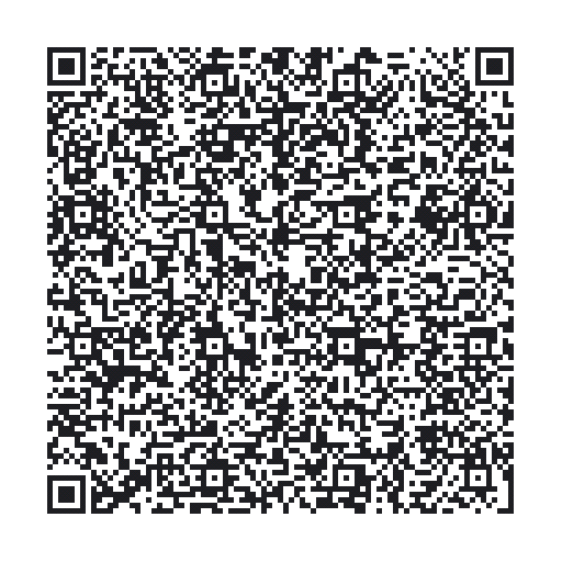
Blynk Shortcut!
If you are having troubles duplicating the functionality above in the Blynk app, scan this QR code with Blynk to get a clone of this experiment!
Program Not Uploading
This happens sometimes; the most likely cause is a confused serial port. You can change this in Tools > Serial Port >
Also, if you get a Timeout error or the IDE could not find your 101 board, try pressing the Master Reset button on the 101, wait around 10 seconds and try re-uploading your sketch.
Still No Success
A broken circuit is no fun. Send us an email, and we will get back to you as soon as we can: techsupport@sparkfun.com