Smart Home Expansion Kit for Arduino 101
 D___Run___
 Introduction
Expanding From the SparkFun Inventor's Kits
Probably the top question we get from returning customers is, "So, I finished a SparkFun Inventor's Kit...what do I do now?" We have never really had a concrete answer...until now.
SIK Expansion Kit - Smart Home
KIT-14156We know that our SparkFun Inventor's Kit (SIK) line of products helps build a great foundation for building circuits and programming a development board to control those circuits. But, if you want to build your own robot, explore the Internet of Things (IoT) or even track the weather in your backyard, it is a big step to take on your own if your only background in electronics is the SIK, the Arduino 101® SIK or the SparkFun Tinker Kit.
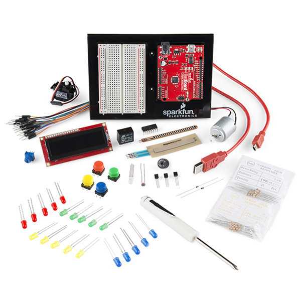
SparkFun Inventor's Kit - V3.3
KIT-13969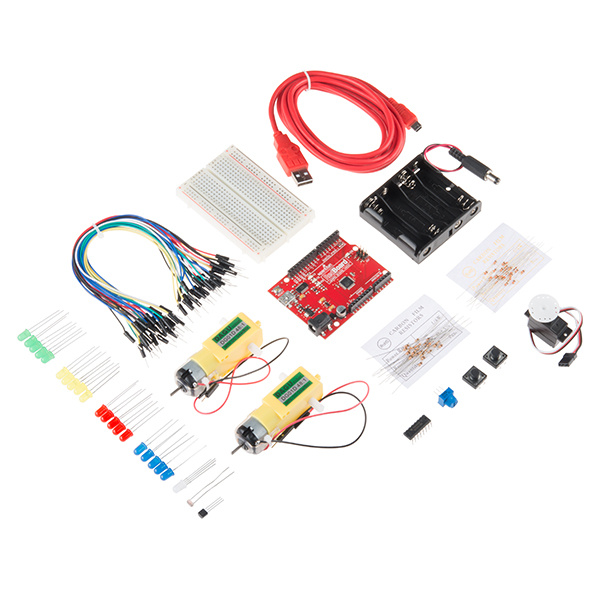
SparkFun Tinker Kit
KIT-13930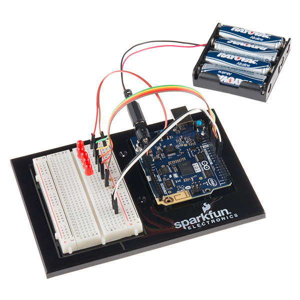
SparkFun Inventor's Kit for Arduino 101
KIT-13844So, we are developing Expansion Kits that are designed to work with our Inventor's Kits to help you dive deeper into the concepts, circuits and code required to build more complicated projects with specific themes in mind.
Smart Home...What Is It?
Here at SparkFun we are always hacking our lives to be easier, faster and just plain cooler with the electronics we build and use. Even though we may like to portray the idea that we live and breathe the office, most of us spend a good deal of time at home, so it is just natural for us to hack our homes.
We have packaged the top sensors and actuators that we have used for hacking and modifying our homes into a single kit to make your life easier and more connected. This guide will be your road map to making your house smarter and more in tune with your life.
You probably bought this kit because you have a voice in your head saying, "I really wish I could detect when a door is opened," or maybe, "How can I tell when my sister has been in my room?" Fear not; this kit will help you answer those questions, but be warned...it will also raise just as many new questions, if not more, which we consider a good thing.
Automation vs. IoT
There is a huge misconception at the moment around home automation. When it comes to a smart home, sometimes the best solution is not always an Internet of Things (IoT) option, especially in terms of security. Sometimes the best solution is not connected to anything at all, but may be the right sensor or actuator for the job used in a creative way.
With that being said, home automation is a great application point for IoT concepts of connectivity, GET requests and interconnected devices. This kit can easily be used with your favorite web-enabled microcontroller to build a number of IoT projects.
This guide, however, will focus on the automation side of things, using the Arduino 101 board and its onboard Bluetooth Low Energy (BLE) capabilities paired with a phone app called Blynk. The focus is on how to make things happen automatically, or at least with minimal control/input from you, to make your life easier, faster and smarter.
A Touch of Blynk
If you have already gone through the SIK for the Arduino 101 board, you have already dabbled a bit with the onboard BLE aspect of the board. Well, this guide will take a deeper dive into BLE using the Arduino 101 board with a smartphone app called Blynk. A number of experiments leverage Blynk in a way that makes sense to give you remote control or sensing capabilities. We don't use Blynk in every experiment, but all circuits have the potential to be integrated into a Blynk project on your own. By the end of this guide, you should be well-versed enough in Blynk and the circuits to go back and build your own around the home Blynk projects.
Choose Your Own Adventure!
This guide is specifically written for the Arduino 101 board to leverage the onboard BLE when using Blynk. But if you have a different development board you are using --- or an Arduino with a WiFi shield, BLE shield or even just a standard UNO tethered to your laptop --- you can still follow along with this guide!
Here are a couple of components that will help you connect your Around-the-Home Kit to Blynk with BLE, WiFi or something else!
BLE
The Arduino 101 board has onboard BLE support for Blynk, but there are a number of other boards and shield that you can connect to Blynk using BLE. Here are a few that we carry, but you can always look up supported hardware on the Blynk website for the most up-to-date hardware list!
SparkFun Simblee BLE Breakout - RFD77101
WRL-13632
LilyPad Simblee BLE Board - RFD77101
DEV-13633
RedBearLab BLE Nano Kit - nRF51822
WRL-14071Wired (Ethernet)
Blynk works through an ethernet connection and is as simple as adding an Ethernet shield to your UNO, using a Yun or even a Raspberry Pi or Tessel 2 if you want to go fancy!
Arduino Ethernet Shield 2
DEV-11166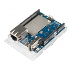
Arduino Yun
DEV-12053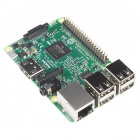
Raspberry Pi 3
DEV-13825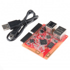
Tessel 2
DEV-13841WiFi
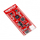
The next layer of connectivity with Blynk is using WiFi. This is by far the most flexible way to connect to your project and offers a truly IoT experience, with your project being able to connect to WiFi that it is within range of and you being able to control and monitor your project from anywhere you have cellular data. There are a number of board options, including a Blynk Board, the ESP8266/ESP32 Thing Boards, and the Intel Edison.
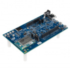
Intel® Edison and Arduino Breakout Kit
DEV-13097
SparkFun Blynk Board - ESP8266
WRL-13794XBee
This has the farthest range of the options above (without going to a cellular development board) but is still tethered to a computer for serial connection. XBee can be used as a USB cable replacement when you are talking to a development board over serial connection. As with the Blynk tethered option, this gives you wireless communication while not having access to a WiFi infrastructure. To explore using XBee with Blynk, check out the kit below and this documentation on using Blynk with an Arduino and no shield.
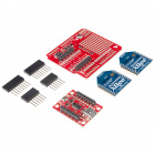
SparkFun XBee Wireless Kit
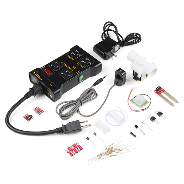
KIT-13197What's in the Kit?
Included Materials
Here are all of the parts in the Around-the-Home Expansion Kit for the SparkFun Inventor's Kit for the Arduino 101 board.
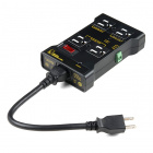
- IoT Relay --- A device that enables you to control an AC outlet using a GPIO pin
- PIR Motion Sensor --- Detects motion using infrared
- BME280 Barometric Pressure/Temperature/Humidity Sensor --- An I2C sensor that measures pressure, temperature, humidity and altitude
- Magnetic Door Switch --- The magnetic door switches you see in home security systems
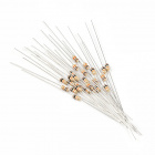
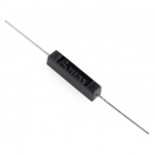
- Sealed Reed Switch --- A magnetically actuated switch, sealed in plastic rather than the standard glass
- N-Channel MOSFET --- N channel MOSFET that is normally open and can control up to 30 volts
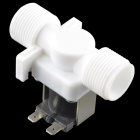
- 12V Solenoid Valve --- Solenoid valve that has 3/4" threads on both ends; should fit on a home garden hose with a simple adapter.
- SparkFun Moisture Sensor --- Changes resistance based on the moisture level between the two prongs
- Non-Invasive Current Sensor --- Sensor that detects the magnetic field generated by current flowing through a wire
- TRRS Breakout --- Breakout board for the Tip, Ring, Ring, Sleeve headphones connector
- 10 uF Capacitor --- A capacitor that stores and releases energy
- Magnet --- Yep...a magnet with a hole in it
- Female Disconnects --- Connectors used to connect bare wire to the tabs on the solenoid valve
- Infrared LED --- An LED that emits infrared light
- Infrared Detector --- Detects the frequency of infrared light that comes in contact with it
Bring Your Own Parts (BYOP)
This kit is designed to expand on the hardware and/or kit you already own. We assume that you have already worked through the SparkFun Inventor's Kit for the Arduino 101 and have most of the parts that came with that kit including an Arduino 101. We will ask you to put some of those parts to use in this experiment guide from time to time. So, go dust of that old SIK or cardboard box of parts, because you are gonna need 'em!
Experiment List
The following is a list of the experiements you will complete using the Around-the-Home Kit. Alternatively, you can navigate around using the buttons on the right.
- Experiment 1: Hello, World...Again
- Experiment 2: Using a Reed Switch
- Experiment 3: RGB Night Light
- Experiment 4: Reading a Door Switch
- Experiment 5: Motion!
- Experiment 6: Controlling a Solenoid with a MOSFET
- Experiment 7: Reading a Moisture Sensor
- Experiment 8: Atmospheric Conditions with BME280
- Experiment 9: Using a Current Sensor
Suggested Reading
Before continuing with this guide, we recommend you be somewhat familiar with the concepts in the following tutorials:
- Arduino 101 SIK Guide --- The step-by-step guide to the SIK for the Arduino 101. Make yourself familiar with this before diving into these experiments.
- Voltage, Current, Resistance and Ohm's Law --- The most basic concepts in electronics and electrical engineering. Get very familiar with these concepts, as they will be used throughout your electronics adventure.
- What Is a Circuit? --- In this guide, we will be building a variety of circuits. Understanding what that means is vital to understanding the Inventor's Kit.
- How to Use a Breadboard --- First time working with a breadboard? Please check out this tutorial! It will help you understand why the breadboard is great for prototyping and how to use one.
Open Source!
At SparkFun, our engineers and educators have been improving this kit and coming up with new experiments for a long time. We would like to give attribution to Oomlout, since we originally started working off the Arduino Kit material many years ago. Both the Oomlout and SparkFun versions are licensed under the Creative Commons Attribution Share-Alike 3.0 Unported License.
To view a copy of this license visit this link, or write: Creative Commons, 171 Second Street, Suite 300, San Francisco, CA 94105, USA.
Setting Up Blynk and the Arduino 101 Board
To make sure everything works smoothly and to ensure that your Arduino 101 board works seamlessly with the device you are going to use to control it with we have some specific steps for you to take to properly configure your Arduino IDE.
Arduino 101 Board Definitions and Libraries
Blynk over BLE with the Arduino 101 requires you to install the newest Blynk Arduino library which needs to be installed through downloading it from gitHub. It also requires you to use an older version of the Arduino 101 board definition files. This portion of the guide will walk you through getting your Arduino environment setup.
Board Definition Files
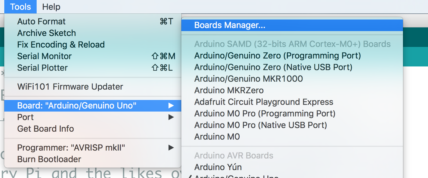
When you installed the Arduino 101 in your Arduino IDE you probably installed the most recent board definition file. Depending on when that was, you may need change that version. To check your board definition version select Tools > Board: > Boards Manager...
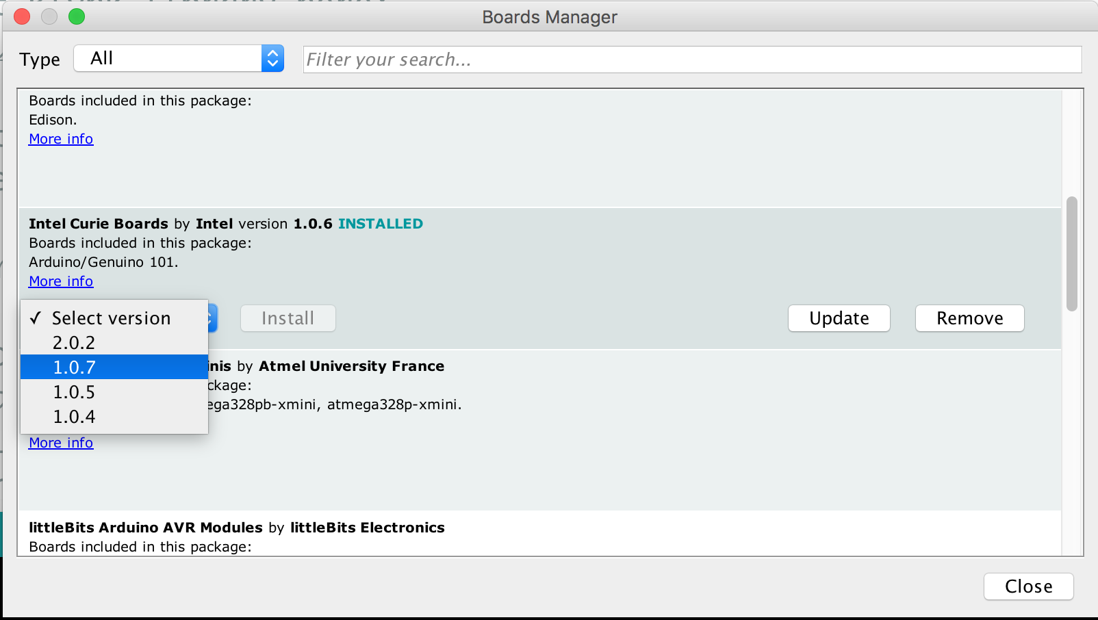
Once you open the boards manager scroll down to your Intel Curie boards and select it. Your board definition file version should be next to the "Intel Curie Boards" title. If the version is higher than 1.0.7 you need to install an older version. To do this use the version drop down menu and select 1.0.7 and click "install". This will change your board definitions.
Finally, for these board definition files to take effect restart your computer.
If You Need to Walk Your Board back to 1.0.7
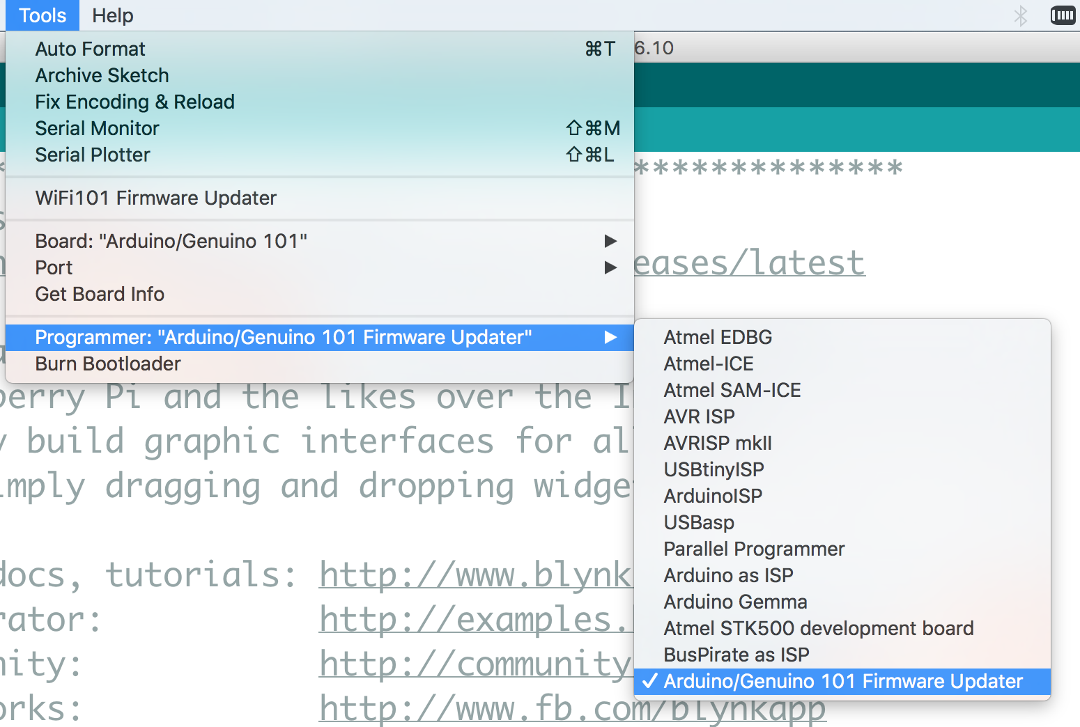
If you have been working with an Arduino 101 board that has the newest firmware on it (2.2.0) you will need to rewrite the bootloader firmware of the board. To do this, be sure that you have installed the 1.0.7 board definitions as shown above. Then connect your Arduino 101 Board to your computer using a USB Cable and in the Arduino IDE set your board to Arduino/Genuino 101 (Tools > Board > Arduino/Genuino 101) and set your correct port (Tools > Port > COM## (Arduino / Genuino 101).
Next, select your programmer by selecting Tools > Programmer > Arduino / Genuino 101 Firmware Updater
Finally, burn the firmware (bootloader) by selecting Tools > Burn Bootloader
You will see the firmware updater stream by in the Arduino IDE console. If you succeeded in updating / back dating your version to 1.0.7 you should see the following output.
Installing the Blynk Libraries
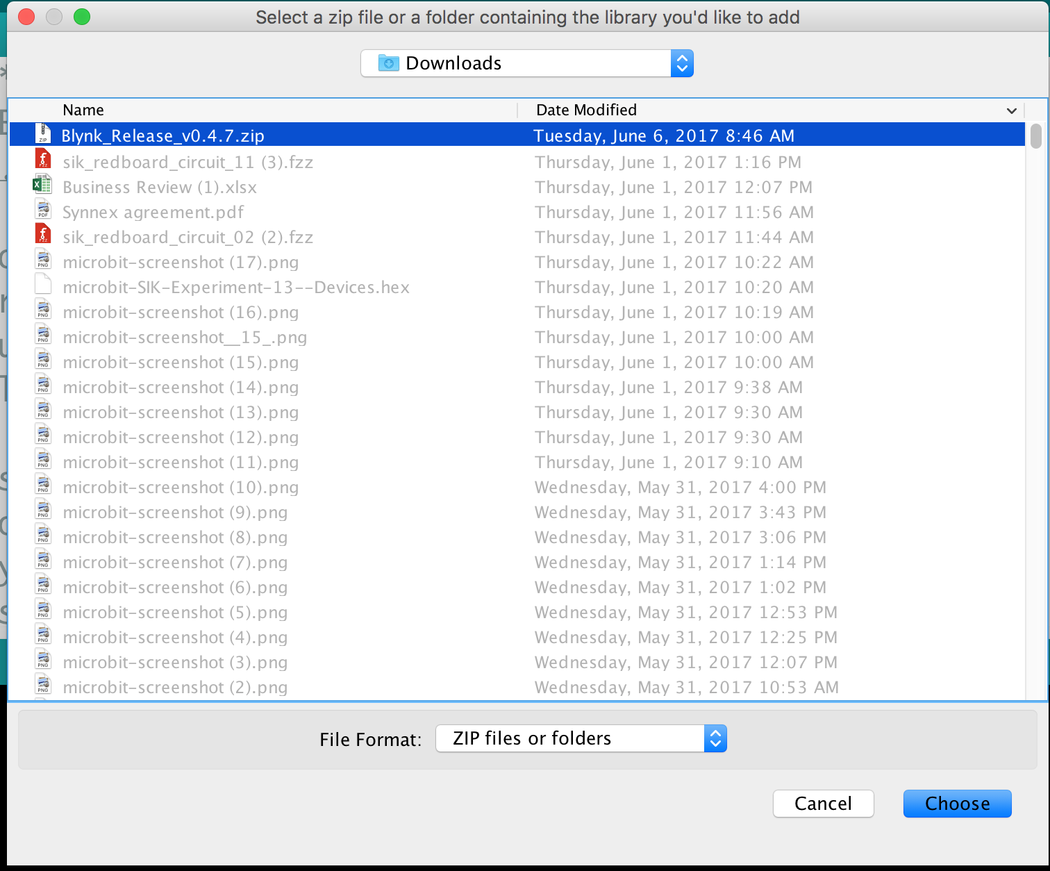
Yes, the heading is not a typo, blynk is actually multiple libraries to make it easier for you in the long run. But, this requires a bit more leg work on your part at the beginning. You need to download the zip file of the library and install it manually. To do so click the button below to download the most current version of the library.
This should download to your Downloads folder, or wherever you have specified your browser to install.
Next, in Arduino navigate to Sketch > Include Library > Add zip Library.... Point the dialog box at the zipped version of the library you just downloaded and select "choose".
This will unzip and install the library for you. You may need to restart Arduino for the library to be visible in your drop down menus.
With that you are ready to go on the hardware side of things, now to get the Blynk app up and running on your phone!
The Blynk App
The Blynk smartphone app comes in two flavors: iOS and Android. But, BLE is only supported by Andriod devices at this time! Before going any further, download the app to your smart device:

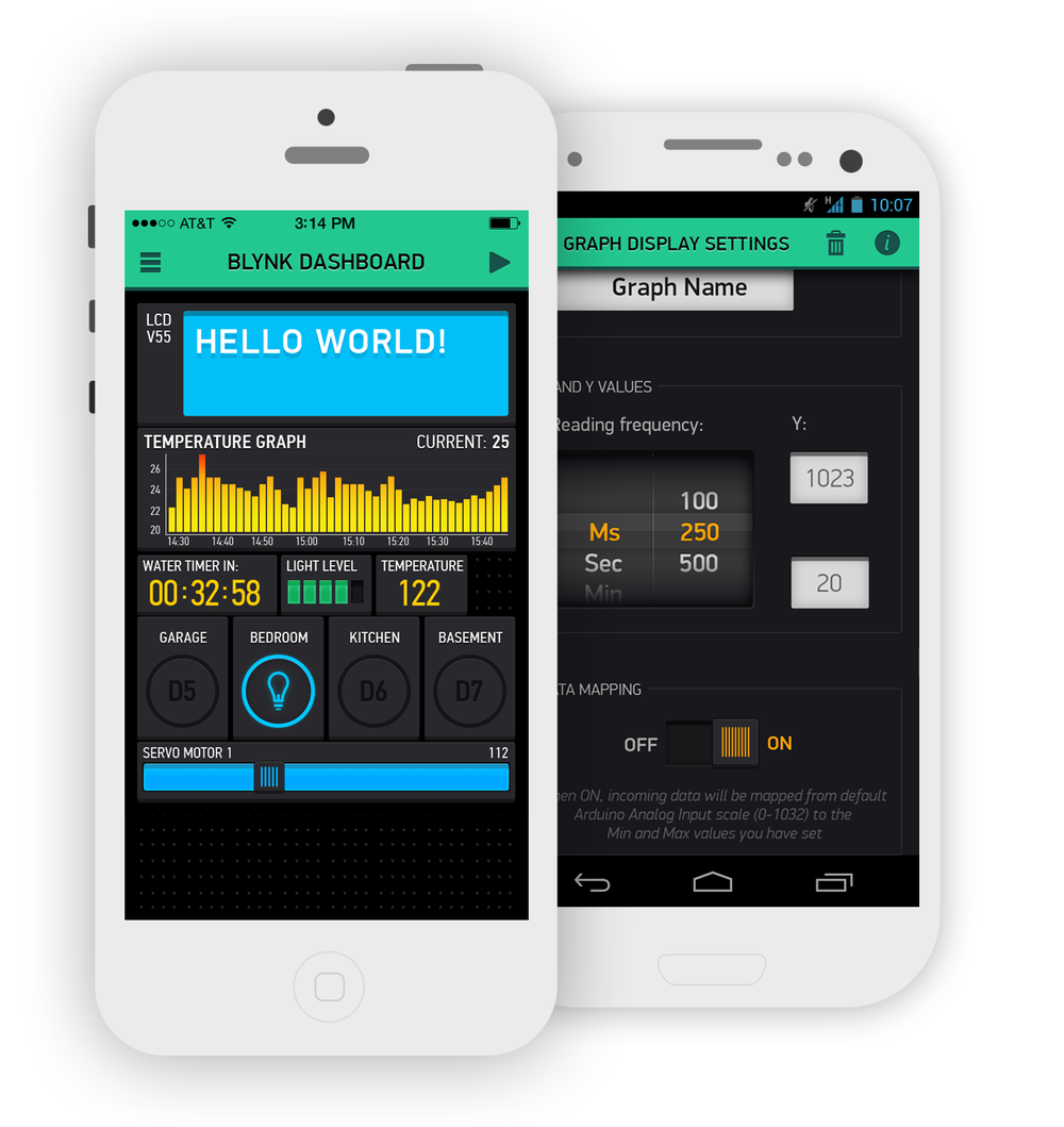
The Blynk app is compatible with Android devices running any version above or equal to 4.0. Blynk was originally designed to control your DIY electronics projects through WiFi. In recent releases Blynk has adopted the ability to control your projects through Bluetooth/BLE, which is exciting for us because that includes support for the Arduino 101!

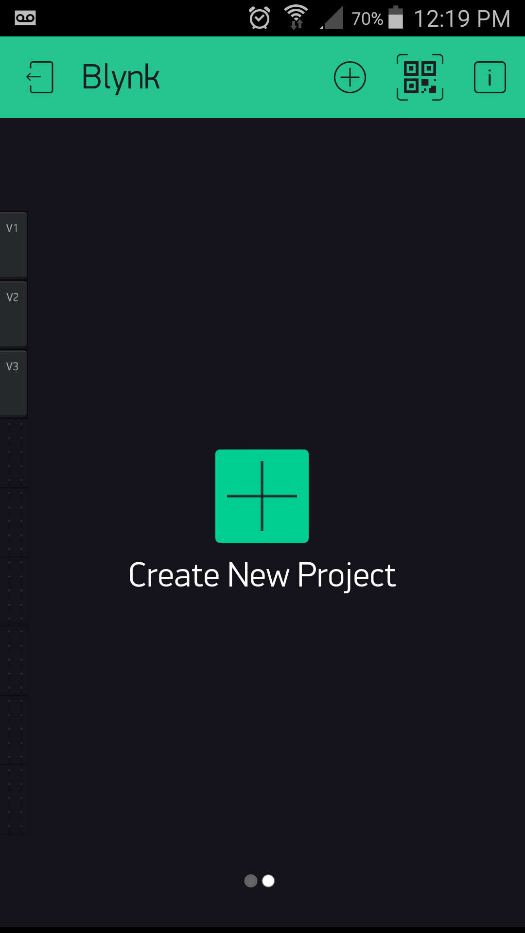
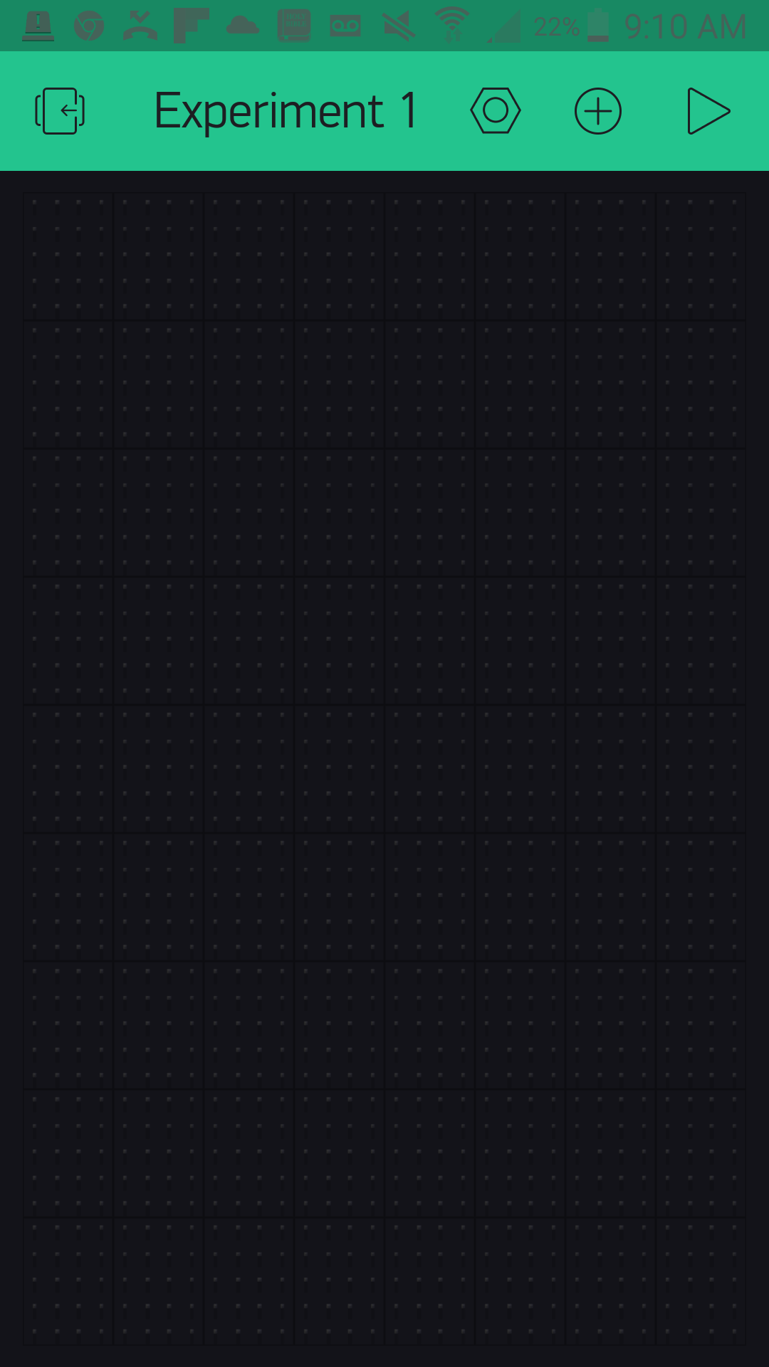
Once you have installed Blynk on your phone or tablet, you can create a project in your app.
Once you name your project, you can select a board and communication method. In this case you should select Arduino 101 and BLE.
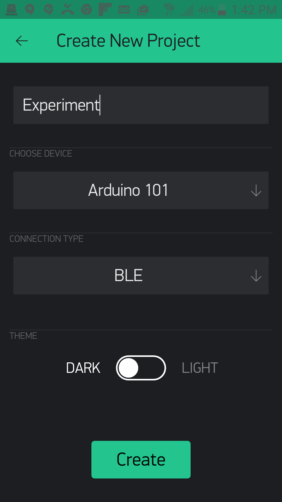
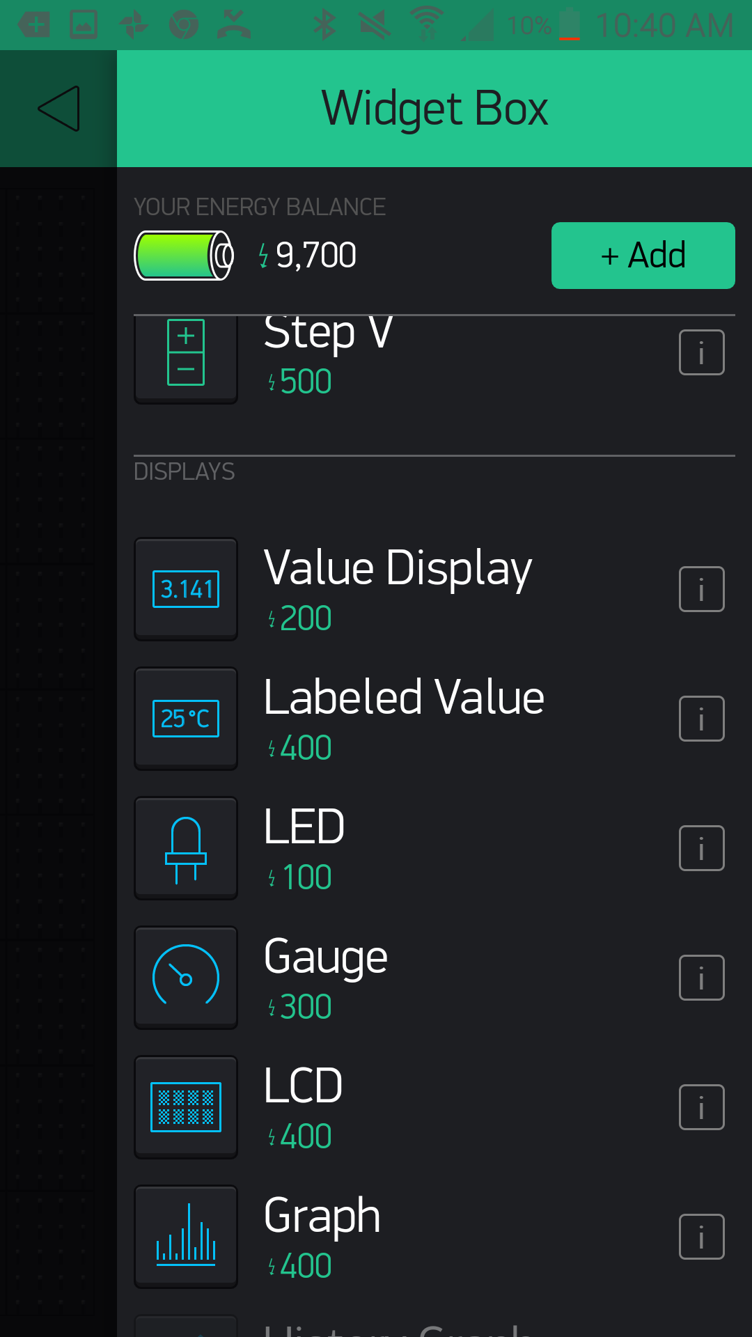
You can then create your app and start to add widgets to it!
Blynk With BLE Has Its Limits
We want to make sure you realize that at this point using Blynk over BLE limits the options of different widgets and tools you can use in your Blynk apps. Once you add the BLE widget to your app, you will notice that other widgets will be grayed out, accompanied by a note about them not being supported yet.
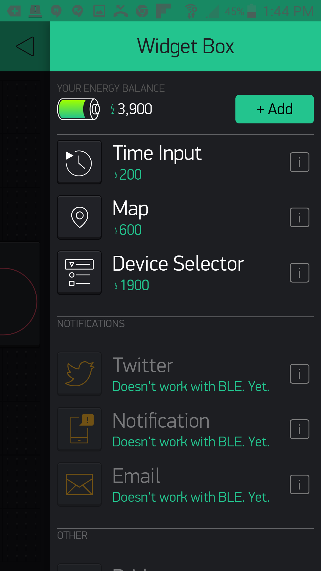
Blynk is well-maintained and updated regularly, so we foresee more and more of these widgets becoming available over time. For now, this documentation uses the widgets that are supported by BLE, and we will update this guide with more experiments as new widgets are supported for use with the Arduino 101 board.
Experiment 1: Hello, World...Again
Introduction
This experiment assumes that you have already gone through the SparkFun Inventor's Kit for the Arduino 101 Board. If you have not, we recommend at least going through the first few experiments here. But, we realize that it may have been awhile for you, so we are going to make sure that everything is up and running and that you can upload code to your Arduino 101 board. Yep, you guessed it: Hello, World...Again! But this time it's with a twist. Let's get blinking!
Parts Needed
You will need the following parts:
- 1x Arduino 101 Board (From your Arduino 101 SIK)
- 1x Breadboard (From your Arduino 101 SIK)
- 1x IoT Relay
- 2x Jumper Wires (From your Arduino 101 SIK)
Didn't Get the Around-the-Home Expansion Kit?
If you are conducting this experiment and didn't get the Around-the-Home Expansion Kit, we suggest using these parts:


Arduino 101
DEV-13787Suggested Reading
Before continuing with this experiment, we recommend you be familiar with the concepts in the following tutorial:
- Light-Emitting Diodes --- Learn more about LEDs
Introducing the IoT Relay
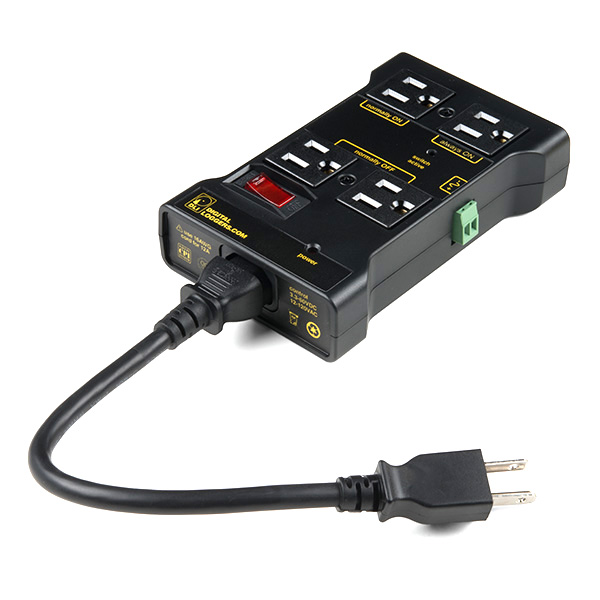
You have turned LEDs on and off, but have you ever wondered how you could use your Arduino 101 to turn bigger things --- like lamps, fans and even your refrigerator --- on and off? Enter the IoT relay!
The IoT relay looks like a simple power strip you would find around your home, but it has a few tricks up its sleeve. First of all you will notice that the plug receptacles are labeled. One is labeled "Normally On," and the other is "Normally Off." This allows you to do a couple of different things. First, you can control whether your GPIO logic from your Arduino is reverse (HIGH = OFF). Or, a little less apparent, is the ability to toggle two different appliances by toggling a GPIO pin. For example, if you plug two lamps in and leave both on, you can toggle which one is on and which one is off by toggling a GPIO pin.
You may ask yourself, "What GPIO pin?" The IoT relay has a screw terminal connection that you supply a signal wire that you can connect to any GPIO pin on your Arduino board, as well as a ground pin connected to the Ground pin on your Arduino. That's it! You can now control any appliance plugged into your IoT relay with an Arduino.
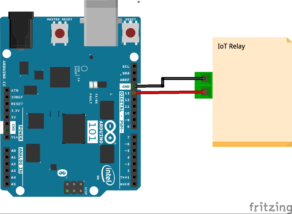
Hardware Hookup
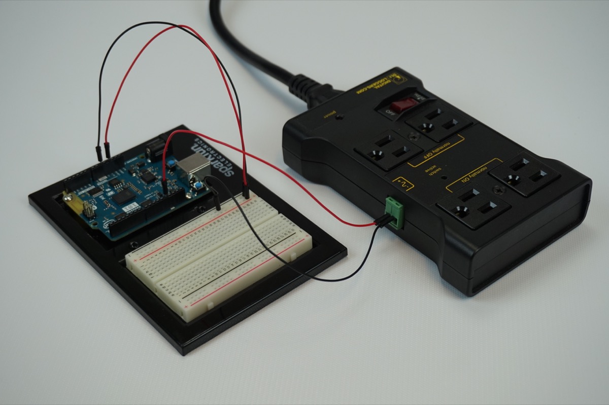
Ready to start hooking everything up? Check out the wiring diagram below to see how everything is connected.
Wiring Diagram for the Experiment
Build Your Blynk App
The last part of this experiment is to build the app itself. You created it earlier to get an authorization token, but now you need to add widgets to be able to control your Arduino 101 board.
Open your Blynk app and navigate to the blank project that you created for this experiment.
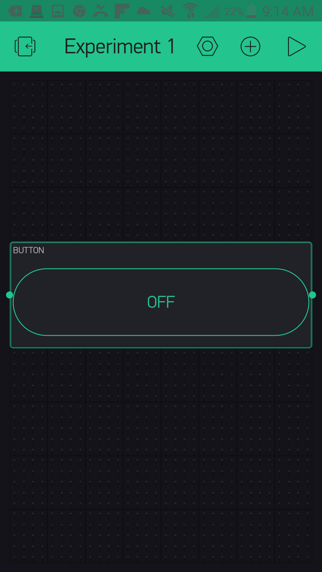
To control the IoT relay, which you have connected to pin 13, you are going to use the button widget in your app. To add the button widget press the (+) logo in the upper right-hand corner of the app. This will bring up a list of widgets as shown below.
Select the Button widget, which will add it to your app. From there you can press and hold to drag the button around your app. Once you have placed it, you can also resize it to fit. We centered ours and made it full width.
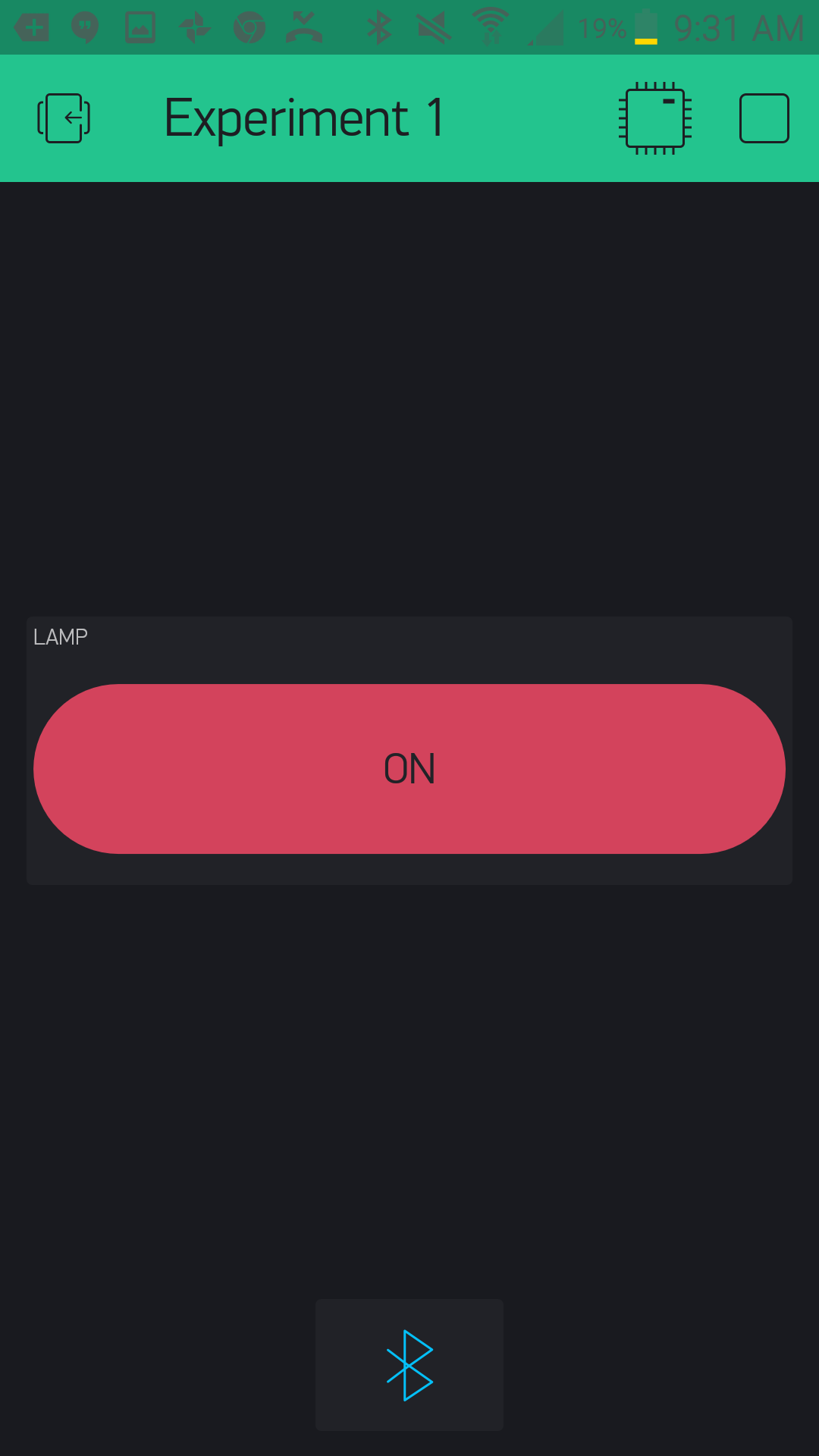
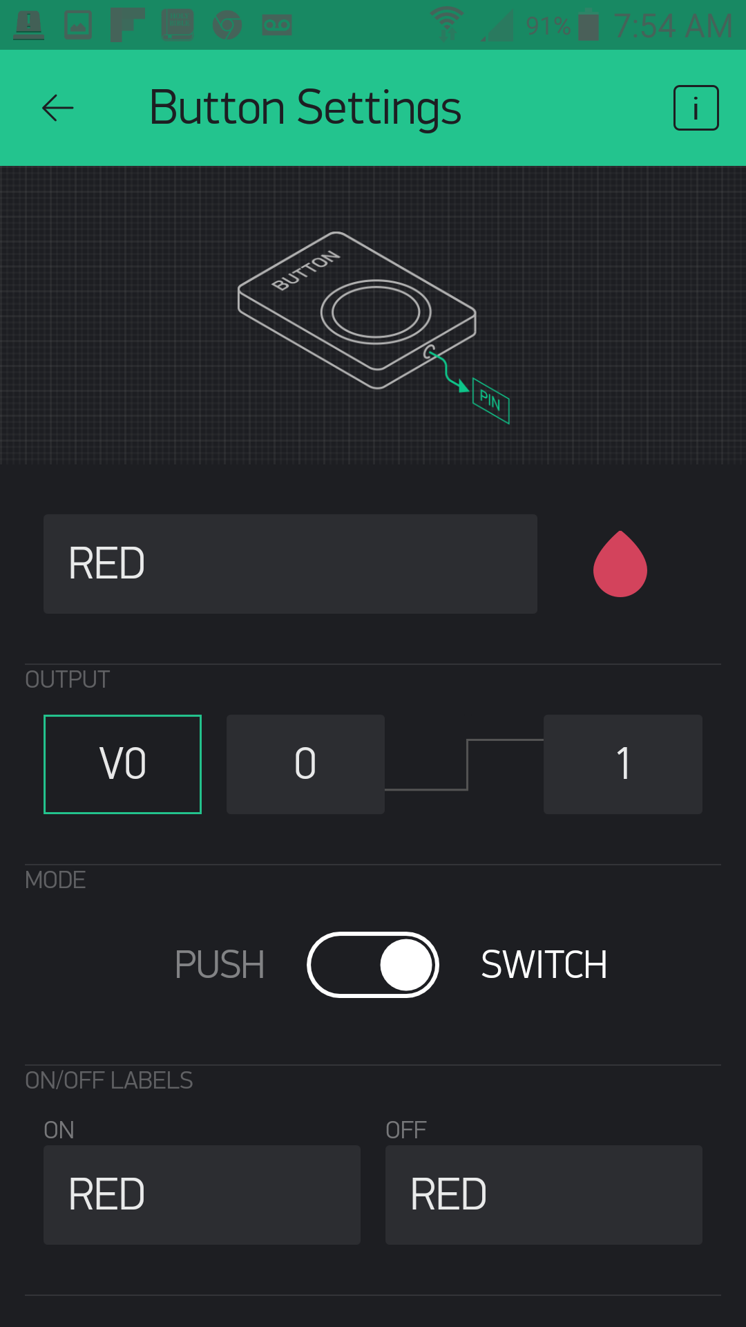
Now to make your button functional! Tapping on the button once will bring up the settings menu for that button. From here you can label the button --- we named ours "Lamp." You then assign the pin that you want it to control --- we chose "D13," or digital pin 13. There are a number of other pins you can use, and we will explore their types in later experiments. Lastly, we selected "switch" as out button functionality so that it stays on or off when we press the button.
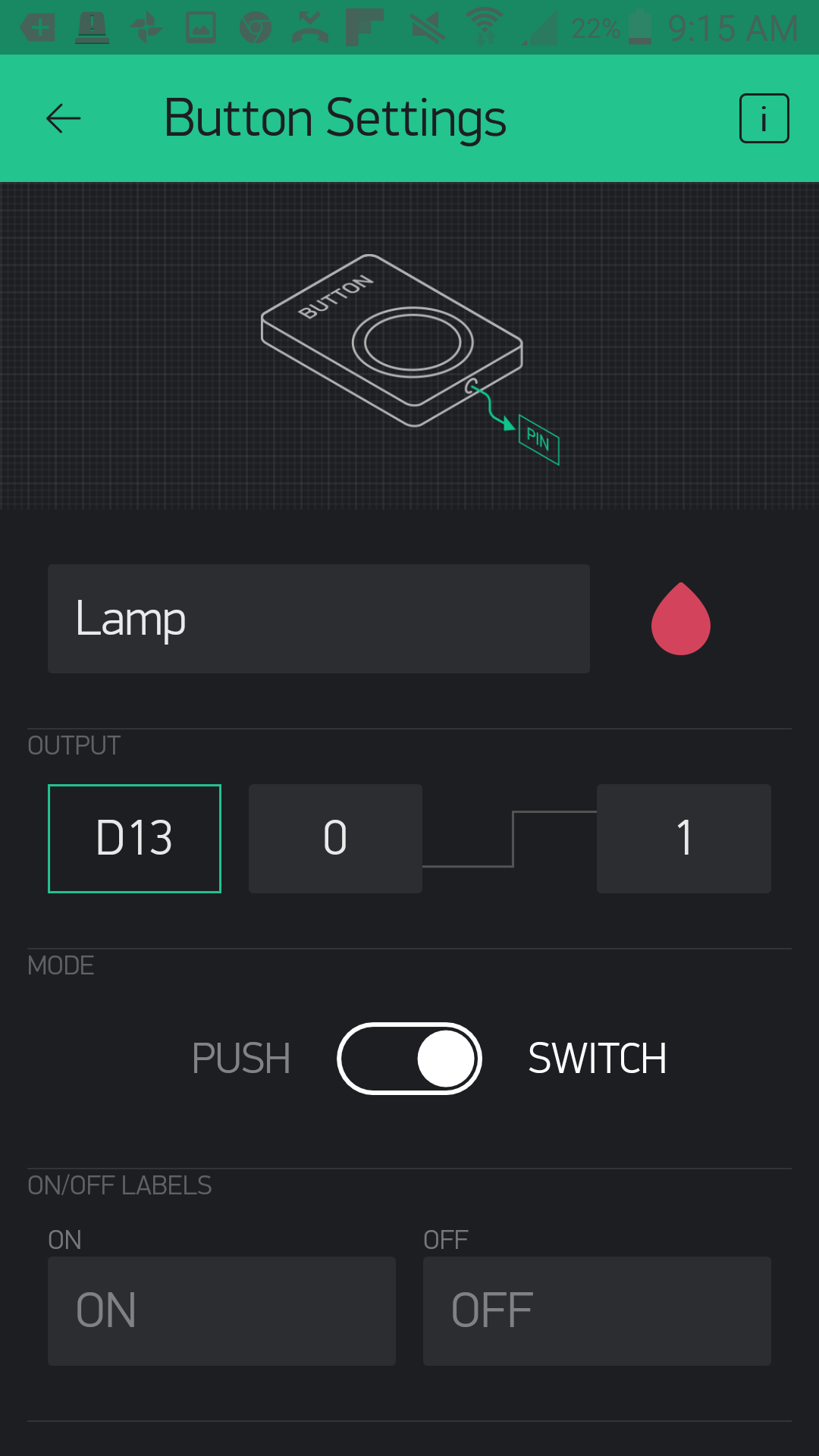
With that you are done with the button! Click the back arrow in the upper left-hand corner.
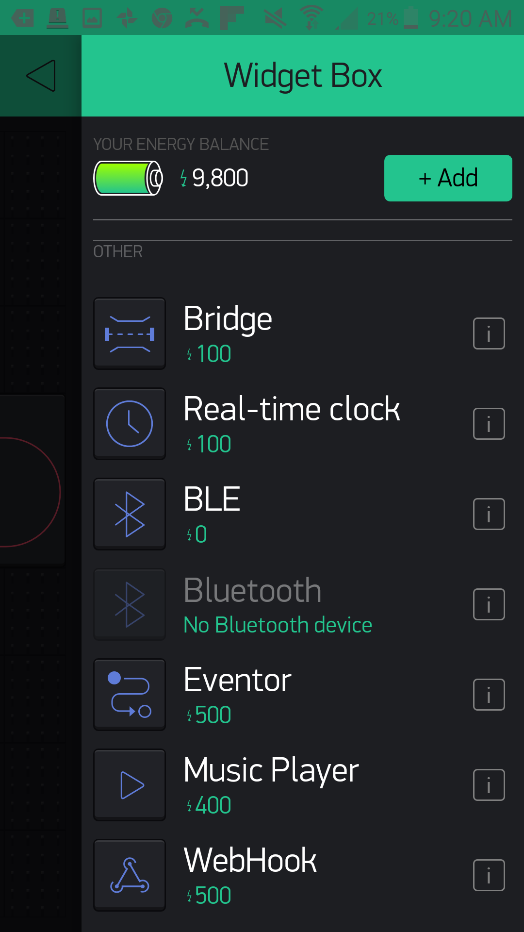
The last thing we need to do --- and something we will have to do with all of our Bynk apps that use the Arduino 101 with BLE --- will be to add the BLE widget to our app. Click the (+) button again and scroll down to find the BLE widget
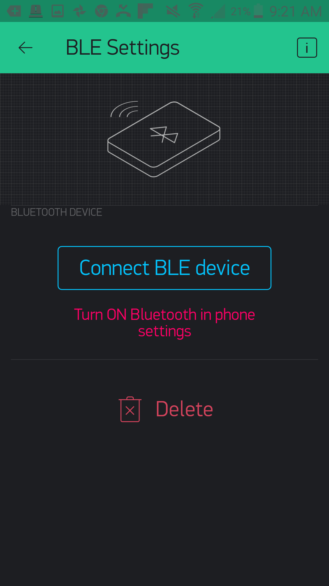
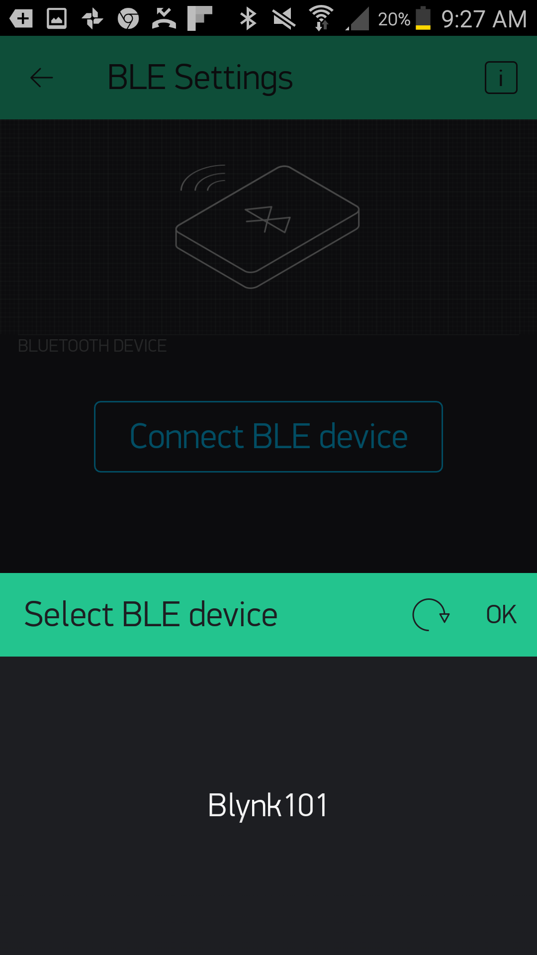
Once you have placed it in your app, go ahead and tap it to open up the BLE settings. You will need to turn Bluetooth and location on in your device for this to work. Click "Connect BLE Device," and Blynk will search for your Arduino 101 board with the name you gave it in the sketch.
If everything works to plan, your Arduino 101 will show up in a list. Go ahead and select it. Your device will connect to your 101 board, and you should get confirmation of connection in the app.
You can now go back to your main app window and run your app by clicking on the play button in the upper right-hand corner. Once the app starts, you can click on the "Lamp" button, and the LED on the Arduino 101 board will turn on and off. But more importantly, whatever you have plugged into your IoT relay will turn on and off!
Before you go ahead and launch your app, be sure to upload the sketch to your Arduino 101 board first!
Upload Your First Sketch
Open the Arduino IDE software on your computer. To find this example/basic sketch to control circuits with Blynk in Arduino, navigate to File > Examples > Blynk > Boards_Bluetooth > Arduino_101_BLE
When you created your app in the previous section, an authorization token was automatically emailed to you. Check your inbox and have the token on hand; you will need to add it to your Arduino sketch before you upload it to your Arduino 101 board.
Replace "YourAuthToken" with your token. Make sure you keep it in quotes as a String; otherwise you will get an error when you try to compile your sketch.
You can also type out or copy and paste the following code into the Arduino IDE. Hit upload, and see what happens!
language:cpp
/********************************************************************************
SparkFun Around-The-Home SIK Expansion Kit, Experiment 1
SparkFun Electronics
Product URL

Controls the IoT relay with the Arduino 101 board through the use of the Blynk app.

This example is written by: Derek Runberg, Educational Technologist

This sketch was written by SparkFun Electronics, with lots of help from the Arduino community.
This code is completely free for any use.

View circuit diagram and instructions at:https://learn.sparkfun.com/tutorials/around-the-home-expansion-kit

********************************************************************************/


//#define BLYNK_USE_DIRECT_CONNECT

#define BLYNK_PRINT Serial

#include <BlynkSimpleCurieBLE.h>
#include <CurieBLE.h>

// You should get Auth Token in the Blynk App.
// Go to the Project Settings (nut icon).
char auth[] = "YourAuthToken";

//create a BLE peripheral object
BLEPeripheral  blePeripheral;

void setup() {
 //start the Serial port at 9600 baud
 Serial.begin(9600);
 //wait 1 second
 delay(1000);

 //give your project a local and device name
 blePeripheral.setLocalName("Exp_01");
 blePeripheral.setDeviceName("Exp_01");
 //set the BLE appearance
 blePeripheral.setAppearance(384);

 //start Blynk
 Blynk.begin(blePeripheral, auth);

 //start the BLE service
 blePeripheral.begin();

 Serial.println("Waiting for connections...");
}

void loop() {
 Blynk.run();
 blePeripheral.poll();
}
Code to Note
The basic blocks of this sketch focus on enabling the Bluetooth on your Arduino 101 board and setting up and running the Blynk firmware. This is the basic example sketch for using the Arduino 101 and BLE with Blynk, and throughout this experiment guide we will be using this as the foundation for other Blynk-based sketches to come. For the sake of reference, here are a few commands that you should have a solid understanding of for use with the experiments:
#define BLYNK_PRINT Serial
This define statement points the Blynk debug console to the Serial port on the Arduino 101. To see this feedback information, hook your Arduino 101 up to your computer using your USB cable and open your Serial monitor. You can all turn this off by commenting this statement out using // in front of the statement. This will help to speed up your sketch and save room.
char auth[] = "YourAuthToken";
When you build a Blynk app, it is assigned an authorization token that gets emailed to the email account attached to the Blynk app. To make sure your Arduino 101 board talks to your app and only your app, you need to replace "YourAuthToken" with your token inside quotes.
language:cpp
blePeripheral.setLocalName("Exp_01");
blePeripheral.setDeviceName("Exp_01");
These commands enable you to give your Arduino 101 board a name that it broadcasts to all BLE-enabled devices around it. As a default throughout this guide we will be using the experiment number, for this experiment it is named "Exp_01", but you can change it to whatever string you would like. We recommend changing both the local name and device name to the same name.
language:cpp
 Blynk.begin(blePeripheral, auth);
 blePeripheral.begin();
On the Arduino 101 board you need to start Blynk first and pass it the blePeripheral object and your authorization token. You then can start the BLE service on your Arduino 101 board.
language:cpp
void loop() {
 Blynk.run();
 blePeripheral.poll();
}
After all of that setup, the loop of this sketch is almost comically short. It contains two methods. The first one runs Blynk, which polls the app on your device and makes sure that it is in sync with what's happening on your board.
The second method does a similar action, but manages your BLE connection between the Arduino 101 and your phone or tablet.
That's it! Like we said, this is the foundation we will be using and adding to over the course of the next eight experiments.
What You Should See
Your lamp that you plugged in to the IoT Relay's "Normally On" plug should turn on and off when you press the button in your Blynk app! Try different appliances or add another lamp to the "Normally Off" plug and use the button to switch between the two different lamps.
Troubleshooting
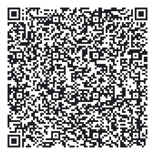
Blynk Shortcut!
If you are having troubles duplicating the functionality above in the Blynk app, scan this QR code with Blynk to get a clone of this experiment!
Program Not Uploading
This happens sometimes; the most likely cause is a confused serial port. You can change this in Tools > Serial Port >
Also, if you get a Timeout error or the IDE could not find your 101 board, try pressing the Master Reset button on the 101, wait about 10 seconds and try re-uploading your sketch.
Still No Success
A broken circuit is no fun. Send us an email, and we will get back to you as soon as we can: techsupport@sparkfun.com
Experiment 2: Using a Reed Switch
Introduction
Detecting the presence of an object is always tough. If you base it off of weight, you always run the risk of someone placing something on your sensor or even just leaning on it. Then there are other, more complicated means that can also produce false positives or negatives.
Enter the reed switch! A reed switch is a simple switch that is triggered by a magnet, so unless you have a lot of magnets sitting around, it gives you an easy way to detect a specific object by simply adding a magnet to it. You can then place the reed switch circuit under a table, under a bowl or plate or even under a drawer to detect if the drawer is opened or closed if you have a powerful enough magnet.
This experiment will build on Experiment 1 where you controlled the IoT Relay with a button in Blynk. You will build an app in Blynk that will help you find your keys by having an indicator LED in the Blynk app turn on if your keys are in a bowl strategically placed by your front door!
Parts Needed
You will need the following parts:
- 1x Breadboard (From your Arduino 101 SIK)
- 1x Arduino 101 Board (From your Arduino 101 SIK)
- 1x Reed Switch
- 2x Jumper Wires (From your Arduino 101 SIK)
- 1x 10k Ohm Resistor (From your Arduino 101 SIK)
- 1x Magnet Ring - 3/16"
Didn't Get the Around-the-Home Expansion Kit?
If you are conducting this experiment and didn't get the Around-the-Home Expansion Kit, we suggest using these parts:


Arduino 101
DEV-13787Suggested Reading
Before continuing with this experiment, we recommend you be familiar with the concepts in the following tutorials:
- Light-Emitting Diodes --- Learn more about LEDs
- Switch Basics --- Learn more about buttons and switches
- Reed Switch Hookup Guide
Introducing the Reed Switch
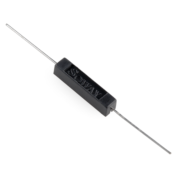
Reed switches are magnetically actuated electrical switches (not magically actuated, though it seems that way sometimes). When the body of the switch is exposed to a magnetic field --- like a magnet or even a strong electrical current --- two ferrous materials inside pull together, the connection closes, and current can flow. In the absence of a magnetic field, the switch opens, as does the circuit it’s a part of.
There are all sorts of creative applications for reed switches. They’re perfect for any projects that require non-contact control. A magnetic door switch, for example, is just a dressed-up reed switch and a mating magnet. By keeping both parts of the switch separate, the door can open and close freely (and maintain its regular duties as a door). The anemometer in our weather meter combines a number of reed switches, which all open and close in order as the wind blows; count the time between switch closures to determine the wind speed.
Here is a quick demonstration of a simple circuit that uses a reed switch to control an LED circuit.
Hardware Hookup
Ready to start hooking everything up? Check out the wiring diagram below to see how everything is connected.
Wiring Diagram for the Experiment

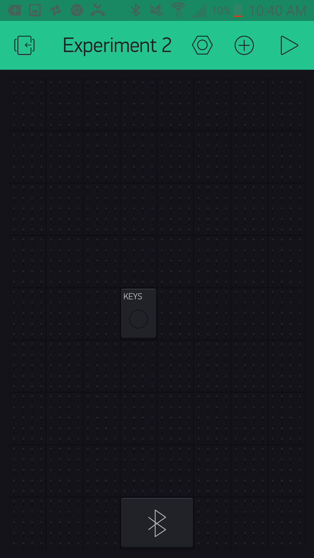
Build Your Blynk App
Start out by building a fresh app in Blynk. Again, your authorization token will be emailed to you; make sure you add it to your Arduino sketch before uploading it!
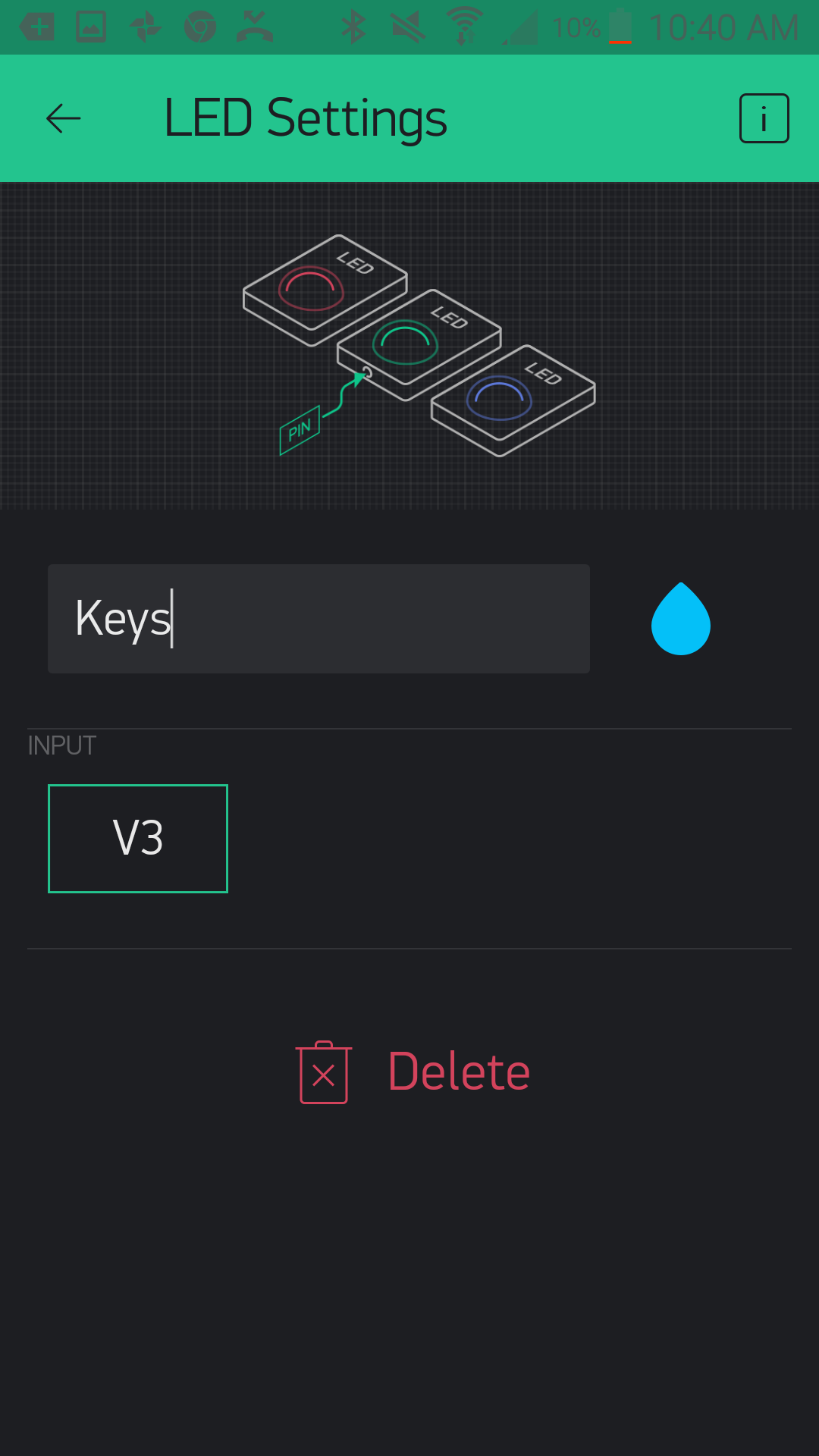
In this new app add an LED widget by clicking the (+) sign in the upper right-hand corner and find the LED widget from the list.
Once you select it and place the widget, open up the settings by pressing once on the widget. Here you can name it as in the previous experiment, and if you want to change the color, you can do so by clicking the teardrop logo next to the name. Finally, set the pin to virtual pin 3 or V3. Notice that the LED widget only accepts virtual pin numbers, which means that if you want to use this widget you need to follow this experiment's example of turning the widget on and off from your Arduino 101 board.
From there you add the BLE widget, as you did in Experiment 1. Be sure to have BLE and location turned on to be able to set up and connect to your Arduino 101 board. From there you should be good to go!
Upload Your Sketch
You will be adding to the example Arduino 101 BLE sketch we used in Experiment 1. Feel free to open that in Arduino by navigating to File > Examples > Blynk > Bluetooth >Arduino_101_BLE or copy and paste the code below.
Make sure you add the authorization key from your Blynk app; otherwise this sketch will not work!
language:cpp
/********************************************************************************
SparkFun Around-The-Home SIK Expansion Kit, Experiment w
SparkFun Electronics
Product URL

Detects the presence of an object attached to a magnet with a reed switch. If a magnet is present it turns on an LED widget in a Blynk app.

This example is written by: Derek Runberg, Educational Technologist

This sketch was written by SparkFun Electronics, with lots of help from the Arduino community.

This code is completely free for any use.

View circuit diagram and instructions at:https://learn.sparkfun.com/tutorials/around-the-home-expansion-kit

********************************************************************************/

/* Comment this out to disable prints and save space */
#define BLYNK_PRINT Serial

#include <BlynkSimpleCurieBLE.h>
#include <CurieBLE.h>


// You should get Auth Token in the Blynk App.
// Go to the Project Settings (nut icon).
char auth[] = "YOUR_AUTH_TOKEN";

// Select your pin with physical button
const int REED_SWITCH = 3;

WidgetLED led3(V3);

BlynkTimer timer;
BLEPeripheral  blePeripheral;

// V3 LED Widget represents the physical button state
boolean reedState = false;
//LED on pin 13
const int LED_PIN = 13;

void setup()
{
  // Debug console
  Serial.begin(9600);

  //give your project a local and device name
 blePeripheral.setLocalName("Exp_02");
 blePeripheral.setDeviceName("Exp_02");
 //set the BLE appearance
 blePeripheral.setAppearance(384);

 //start Blynk
 Blynk.begin(blePeripheral, auth);

 //start the BLE service
 blePeripheral.begin();
  // Setup physical button pin (active low)
  pinMode(REED_SWITCH, INPUT);
  //set LED_PIN as output
  pinMode(LED_PIN,OUTPUT);

  timer.setInterval(100L, checkState);
}

void loop()
{
  Blynk.run();
  blePeripheral.poll();
  timer.run();
}

void checkState()
{
  // Read switch
  boolean isPressed = (digitalRead(REED_SWITCH) == HIGH);

  // If state has changed...
  if (isPressed != reedState) {
    if (isPressed == HIGH) {
      led3.on();
      digitalWrite(LED_PIN,HIGH);
    } else {
      led3.off();
      digitalWrite(LED_PIN,LOW);
    }
    reedState = isPressed;
  }
}
Code to Note
In this example we read the reed switch and, depending on its state, we turn the LED widget in the app on or off.
BlynkTimer timer;
The lessons learned here are that you can create a widget object in your Arduino sketch and control it via code. Also, the idea of a timer is important here. If we placed all of our code into the loop() Arduino and Blynk would throw overflow errors. We can only send so much data to our Blynk app before it gets overwhelmed. So, we use the BlynkTimer object to set a time interval for a custom function --- in this case, check the state of the reed switch and toggle the LedWidget depending on that value.
const int REEDSWITCH = 3;
In this sketch we store the pin number that the reed switch is connected to as a global constant integer. We do this so we can easily change the pin number in one place at the top of the sketch, but also so the pin number cannot be changed in code for any reason. This is safe programming practice that we will employ throughout this set of experiments.
WidgetLED led(V3);
The Blynk library for Arduino doesn't use the conventional setup and use for pins using the Arduino language. Instead, it uses object notation! So, to create an LED widget you define an object of WidgetLED (we called ours "led") and then pass it the virtual Blynk pin that you would like to assign to it --- in this case v3, or virtual pin 3.
boolean isPressed = (digitalRead(REED_SWITCH) == LOW);
Inside of the custom function we create a local Boolean variable called isPressed and store the state we get from the logical statement on the reed switch. If a magnet is present, this value will be true; if it is absent, the value will be false.
language:cpp
  // If state has changed...
  if (isPressed != reedState) {
    if (isPressed == true) {
      led3.on();
    } else {
      led3.off();
    }
    reedState = isPressed;
  }
We finally use an if() statement to control the LED widget. If the isPressed variable is equal to true the LED widget will turn on. If the state variable is false the widget will be off.
Notice that there is a bit of a delay between removing the magnet and the LED widget toggling. This is due to a bit of latency built up between the BLE polling and the timer. In this application this works because we are looking for the presence of something that doesn't move that often.
What You Should See

When you hold a magnet close to the reed switch, the LED on connected to pin 13 on the Arduino 101 should turn on, and the LED widget in your app should also turn on. When the magnet is removed, the LED and the widget indicator should turn off.
A great application for this circuit would be to find a bowl for your keys and insert this circuit in the base. Hook up the IoT Relay to pin 13 on the Arduino 101 as shown in Experiment 1. Then, place the magnet on your key chain. When you get home late at night, all you need to do is throw your keys into your newly built bowl, and a lamp plugged into the IoT Relay will turn on. When you are in a rush to leave and can't find your keys, you can check to see if they are where they should be or not. When you take the keys from the bowl, the lamp turns off as you leave.
The great thing about this small experiment is that it highlights that not everything has to be connected to Blynk or Arduino in order for the two functions to work. You can use Blynk or not, and it doesn't get in the way of the Arduino sketch!
This experiment may seem overly simple, but it is here as something for you to build off of. Add other sensors and LED widgets to create indicators for different states of a project. Blynk has almost infinite virtual pins, so you are limited only by the number of LED widgets you can fit on your screen!
Troubleshooting
Blynk Shortcut!
If you are having troubles duplicating the functionality above in the Blynk app, scan this QR code with Blynk to get a clone of this experiment!
Program Not Uploading
This happens sometimes; the most likely cause is a confused serial port. You can change this in Tools > Serial Port > and make sure you are using an Arduino 101 board.
Not Connecting to the Blynk App
Be sure to check that your Bluetooth is on. Also make sure your authorization token is correct and in your sketch!
Still No Success
A broken circuit is no fun. Send us an email, and we will get back to you as soon as we can: techsupport@sparkfun.com
Experiment 3: RGB Night Light
Introduction
OK, your mind has been blown by your newly found superpowers of using the Blynk app with the Arduino 101 board. Before moving on to new parts and concepts to get creative with, we want to highlight something for you: the idea that you have an entire Inventor's Kit for the Arduino 101 board at your disposal in terms of other parts to use and leverage.
In this experiment we will build on your previous experience with the SIK for the Arduino 101 board and the hardware that came with it to highlight that, by adding Blynk to the equation, you have quite the toolkit available to you in terms of parts to use to build interconnected devices and projects.
We are going to take the night-light circuit you built in Experiment 3 from the Arduino 101 SIK Experiment Guide and modify it into a project that uses Blynk to make it more interactive through the use of an RGB LED that you will be able to control the color of. With this custom-colored night light, your bathroom ambiance will never be the same!
Parts Needed
You will need the following parts:
- 1x Breadboard (From your Arduino 101 SIK)
- 1x Arduino 101 Board (From your Arduino 101 SIK)
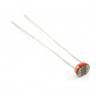
- 1x Light Sensor (From your Arduino 101 SIK)
- 1x 10k Ohm Resistor (From your Arduino 101 SIK)
- 1x RGB LED Clear Common Cathode (From your Arduino 101 SIK)
- 3x 100 Ohm Resistors (From your Arduino 101 SIK)
- 9x Jumper Wires (From your Arduino 101 SIK)
Didn't Get the Around-the-Home Expansion Kit?
If you are conducting this experiment and didn't get the Around-the-Home Expansion Kit, we suggest using these parts:

Arduino 101
DEV-13787Suggested Reading
Before continuing with this experiment, we recommend you be familiar with the concepts in the following tutorials:
- Light-Emitting Diodes --- Learn more about LEDs
- Switch Basics --- Learn more about buttons and switches
- Reed Switch Hookup Guide
Introducing the Red Green Blue (RGB) LED
We know that the RGB is probably nothing new to you at this point, but we wanted to give you a bit of a refresher course if it has been awhile.
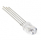
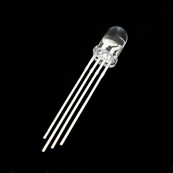
The Red Green Blue (RGB) LED is three LEDs in one. The RGB has four pins with each of the three shorter pins controlling an individual color: red, green or blue. The longer pin of the RGB is the common ground pin. You can create a custom-colored LED by turning different colors on and off to combine them. For example, if you turn on the red pin and green pin, the RGB will light up as yellow.
But which pin is which color? Pick up the RGB so that the longest pin (common ground) is aligned to the left as shown in the graphic below. The pins are Red, Ground, Green and Blue --- starting from the far left.
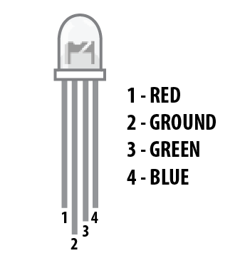
**Note: When wiring the RGB, each colored pin still needs a current-limiting resistor in line with the 101 pin that you plan to use to control it, as with any standard LED. **
Hardware Hookup
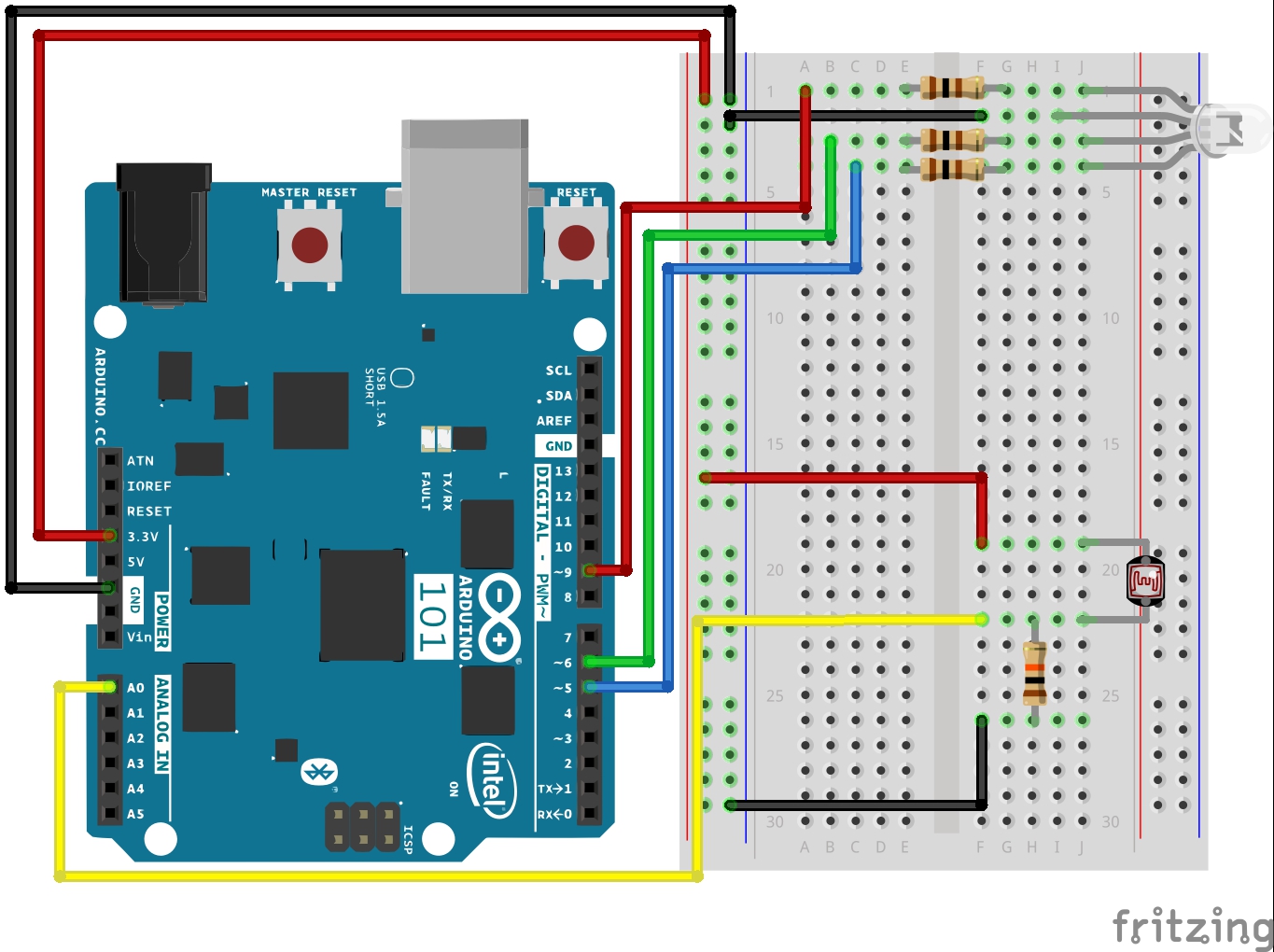
Ready to start hooking everything up? Check out the wiring diagram below to see how everything is connected.
Wiring Diagram for the Experiment
Build Your Blynk App
Start out by building a fresh app in Blynk. Again, your authorization token will be emailed to you; make sure you add it to your Arduino sketch before uploading it!
In this new app, add a zeRGBa widget by clicking the (+) sign in the upper right-hand corner and find the zeRGBa widget from the list.
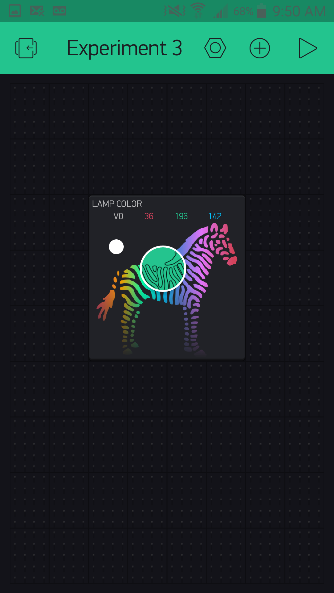
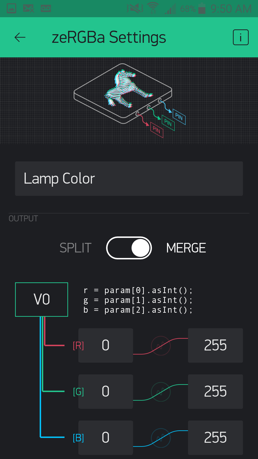
Once you select it and place the widget, open up the settings by pressing once on the widget. Here you can name it like the previous experiment. Finally, set the pin to virtual pin 0 or V0. The zeRGBa widget also has two ways to control pins. You can directly control the pins by using the Split setting and assign each color a pin.
If you are looking to play around with just an RGB and Blynk, this is a fun option to explore later. We want to use the Merge option, which merges the 3 RGB values into an array of values.
From there you add the BLE widget, as you did in Experiment 1. Be sure to have BLE and location turned on to be able to set up and connect to your Arduino 101 board. From there you should be good to go!
Upload Your Sketch
Copy and paste or type out the code below.
Make sure that you add the authorization key from your Blynk app; otherwise this sketch will not work!
language:cpp
/********************************************************************************
SparkFun Around-The-Home SIK Expansion Kit, Experiment 3
SparkFun Electronics
Product URL

Build an RGB night light where you use the Blynk App to configure the color of the RGB when it is lit.

This example is written by: Derek Runberg, Educational Technologist

This sketch was written by SparkFun Electronics, with lots of help from the Arduino community.
This code is completely free for any use.

View circuit diagram and instructions at:https://learn.sparkfun.com/tutorials/around-the-home-expansion-kit

********************************************************************************/

//#define BLYNK_USE_DIRECT_CONNECT

/* Comment this out to disable prints and save space */
#define BLYNK_PRINT Serial


#include <BlynkSimpleCurieBLE.h>
#include <CurieBLE.h>

// You should get Auth Token in the Blynk App.
// Go to the Project Settings (nut icon).
char auth[] = "YOUR AUTH TOKEN";

BLEPeripheral  blePeripheral;

//RGB pin constants
const int RED_PIN = 9;
const int GREEN_PIN = 6;
const int BLUE_PIN = 5;

//sensor pin constant set at A0
const int SENSOR_PIN = A0;

//preset color of the RGB... Red!
int r = 255;
int g = 0;
int b = 0;
int calibrationVal;

void setup()
{
  // Debug console
 Serial.begin(9600);

 delay(1000);

 blePeripheral.setLocalName("Exp_03");
 blePeripheral.setDeviceName("Exp_03");
 blePeripheral.setAppearance(384);

 Blynk.begin(blePeripheral, auth);

 blePeripheral.begin();

 Serial.println("Waiting for connections...");
 calibrationVal = analogRead(SENSOR_PIN);
}

void loop()
{
  int lightVal = analogRead(SENSOR_PIN);
  //if lightVal is less than the calibration value - 50 (it's dark)...
  if (lightVal < calibrationVal - 50) {
    //display set color
    analogWrite(RED_PIN, r);
    analogWrite(GREEN_PIN, g);
    analogWrite(BLUE_PIN, b);
   }
  else {
    //RGB is off
    analogWrite(RED_PIN, 0);
    analogWrite(GREEN_PIN, 0);
    analogWrite(BLUE_PIN, 0);
  }

  blePeripheral.poll();
  Blynk.run();
}

// zeRGBa assigned to V0
BLYNK_WRITE(V0)
{
  // get a RED channel value
  r = param[0].asInt();
  // get a GREEN channel value
  g = param[1].asInt();
  // get a BLUE channel value
  b = param[2].asInt();
}
Code to Note
In this sketch a lot should look pretty familiar to you. We covered the idea of building a light sensor-based night light in the SIK for Arduino 101 Experiment Guide if you would like to see where we started from here.
In this experiment we use the RGB LED instead of a single LED, which should also be somewhat familiar to you. The focus of this experiment is how we set the color and interact with the RGB through Blynk. Here are a few pieces of code that highlight the Blynk functionality.
char auth[] = "YOUR AUTH TOKEN";
We miss this all the time, so you probably do as well. We want to make sure that you are using your authorization token when you upload the sketch, and not just hitting upload. Be sure to change this string to the token Blynk emails to you.
language:cpp
 //preset color of the RGB... Red!
int r = 255;
int g = 0;
int b = 0;
Part of what we are demonstrating with this sketch is making sure that there is enough information in the Arduino sketch for it to function without any input from Blynk from the beginning. With that in mind, we pre-set the RGB color to an intense red (go figure!). The RGB will then stay red until someone connects to the Arduino 101 with Blynk and changes the color. Since these variables are global, when you change the color with the Blynk app, the color will stay the same even when you disconnect the app from the Arduino 101 board.
language:cpp
 // zeRGBa assigned to V0
BLYNK_WRITE(V0)
{
  // get a RED channel value
  r = param[0].asInt();
  // get a GREEN channel value
  g = param[1].asInt();
  // get a BLUE channel value
  b = param[2].asInt();
}
The Blynk API uses event functions. As it polls your Blynk app for changes using the blynk.run() method, it triggers this event function called BLYNK_WRITE(V0) when data is written to virtual pin 0 in Blynk. When you change your zeRGBa widget, it writes an array of values with a red value being the first, a green value the second, and a blue the last. We parse that array of values within the event function and set the global color variables to the appropriate value. We will use this concept later in other experiments as well, so we wanted to be sure to highlight it in detail now.
What You Should See
Now, plug your project in where you would like a night light. At first nothing will happen. Turn the lights in the room off or cover the light sensor. The RGB should turn on with a red color. Now connect to your Arduino 101 board with Blynk and use the zeRGBa to change the color of your RGB.
Now if you turn the lights on, the RGB will turn off. Turn your lights back off, and the RGB should turn back on with the color you picked earlier. As long as you don't unplug the Arduino 101 board, the RGB will stay this color whether you use the Blynk app or not. To change the color, use Blynk!
This experiment may seem a bit simple, but it is here to inspire you to incorporate the parts you already have in your SIK for the Arduino 101 board, as well as to think creatively about how to use Blynk and BLE where it makes sense.
Troubleshooting
Blynk Shortcut!
If you are having troubles duplicating the functionality above in the Blynk app, scan this QR code with Blynk to get a clone of this experiment!
Program Not Uploading
This happens sometimes; the most likely cause is a confused serial port. You can change this in Tools > Serial Port > and make sure you are using an Arduino 101 board.
Not connecting to the Blynk App
Be sure to check that your Bluetooth is on as well as your location setting. Also make sure your authorization token is correct and in your sketch!
RGB shows wrong colors
Double check your wiring, you may have the wrong color controlled by the wrong pin on the Arduino 101
Experiment 4: Reading a Door Switch
Introduction
In Experiment 2 you learned how to use a simple reed switch with Blynk and Arduino. In this experiment you will take this a step further and into the world of home security with the magnetic door switch. We will be using Blynk and the Arduino 101 board to arm and disarm your burglar alarm...so watch out, burglars!
Parts Needed
You will need the following parts:
- 1x Breadboard
- 1x Arduino 101 Board
- 1x Magnetic Door Switch
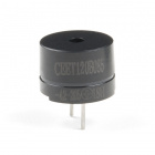
- 1x Buzzer
- 6x Jumper Wires
Didn't Get the Around-the-Home Expansion Kit?
If you are conducting this experiment and didn't get the Around-the-Home Expansion Kit, we suggest using these parts:
Arduino 101
DEV-13787Suggested Reading
Before continuing with this experiment, we recommend you be familiar with the concepts in the following tutorials:
- Light-Emitting Diodes --- Learn more about LEDs
- Switch Basics --- Learn more about buttons and switches
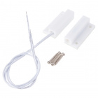
Introducing the Magnetic Door Switch
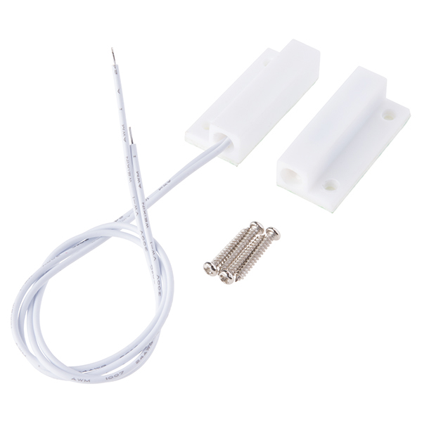
In Experiment 2 you built a circuit containing a reed switch controlled by direct magnet contact: someone placing a magnet on top of the sensor. The door switch included in this kit is roughly the same, but with a specific application in mind as well as wiring added to it so that you can place the sensor a little further away.
The switch assembly has two pieces. When the two halves of the switch assembly are very near each other, or touching, the switch is in one state. Moving the two halves more than 20mm apart from each other will cause the switch to change state. One half contains a magnet, and the other contains a reed switch, a switch that changes state when exposed to a magnetic field.
This type of two-piece switch is often used in home-security systems. One half of the switch is attached to a fixed surface, and the other half to a moving door or window. When the door or window is opened, the two halves are separated from each other, breaking the contact and changing the switch’s state.
Here is a bit of a throwback video description of the door sensor and what it includes for your nostalgic record.
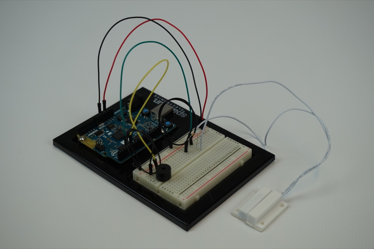
Hardware Hookup
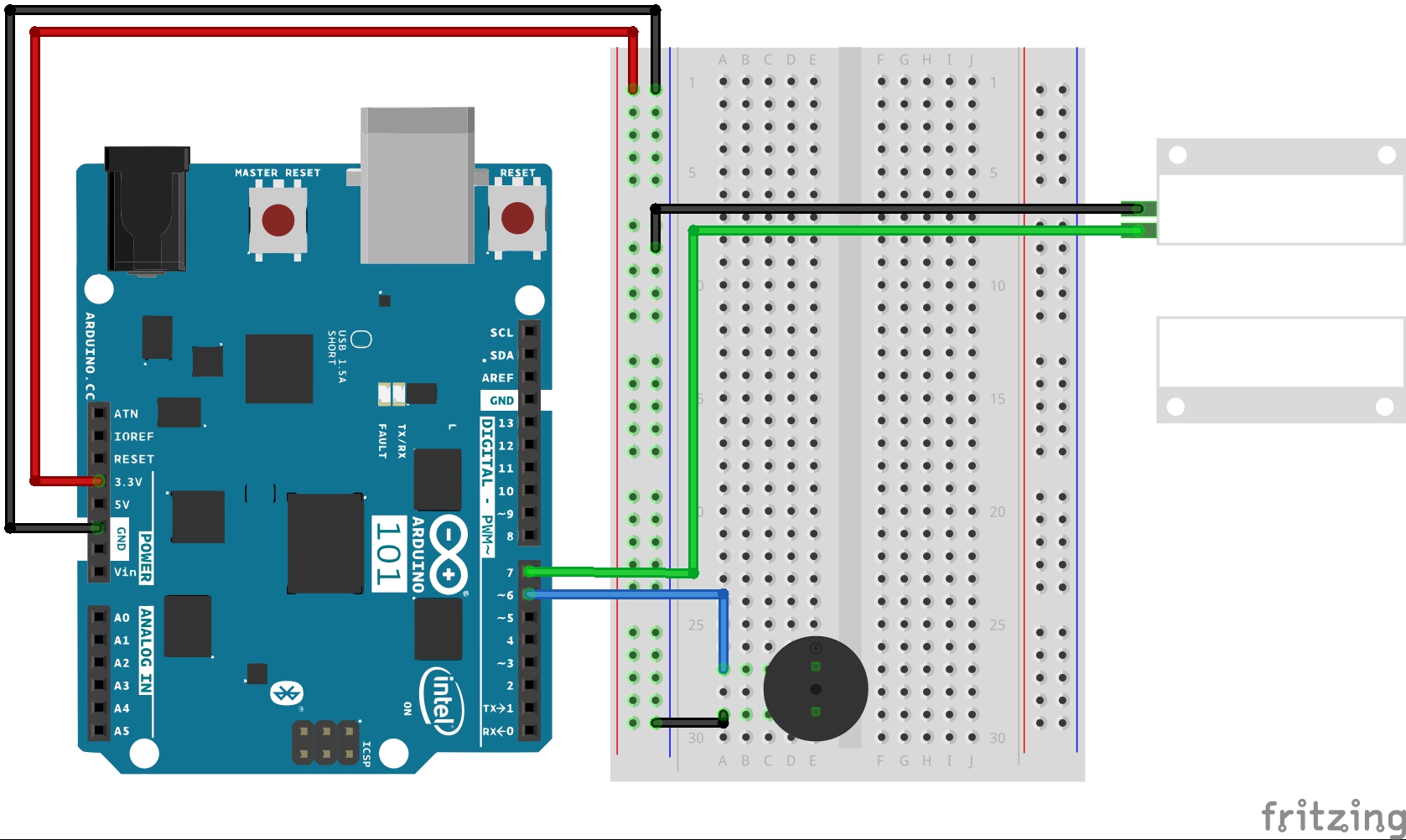
Ready to start hooking everything up? Check out the wiring diagram below to see how everything is connected.
Wiring Diagram for the Experiment
Build Your Blynk App
Your Blynk app will be your way to arm, disarm, silence and check to see if someone has entered through the door and maybe figured out how to disable the buzzer in some way.
The app consists of two button widgets and an LED widget. One button will control the arming and disarming of the system; the other will be a silencing button to turn the alarm on and off. Finally the LED will be a silent alarm where you can open the app and check to see if someone has entered or not; it will blink if the alarm has been tripped.
To start out, create a new Blynk app and add the BLE widget. Be sure to turn BLE and location on so your phone can connect to the Arduino 101 board using BLE.
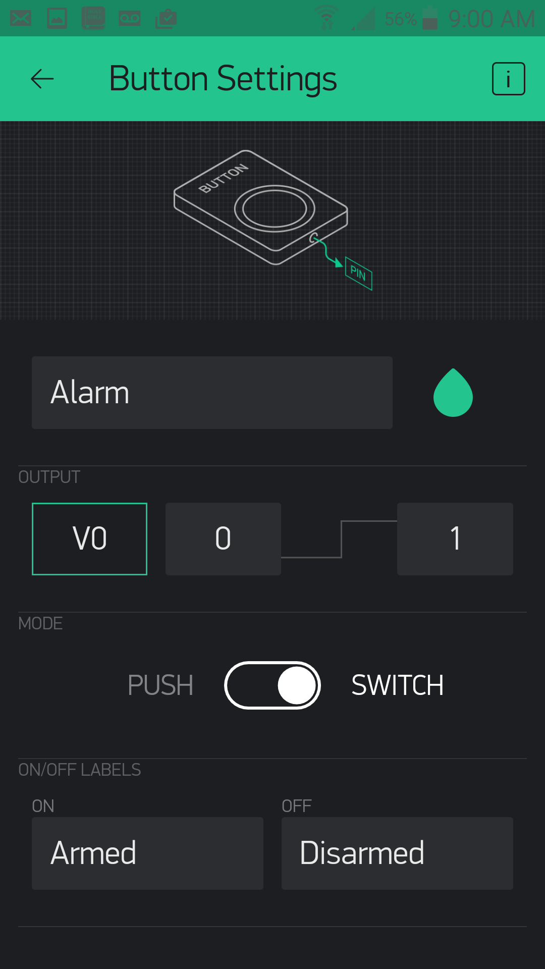
Start out by adding a button. We named it "Alarm" and put it into switch mode. The on and off values are "Armed" and "Disarmed." The pin that the button is connected to is virtual pin 0 or V0.
Add another button. This one we named "Silence," which is connected to virtual pin 1 or V1 and also in "switch" mode. We left the on/off labels as they were.
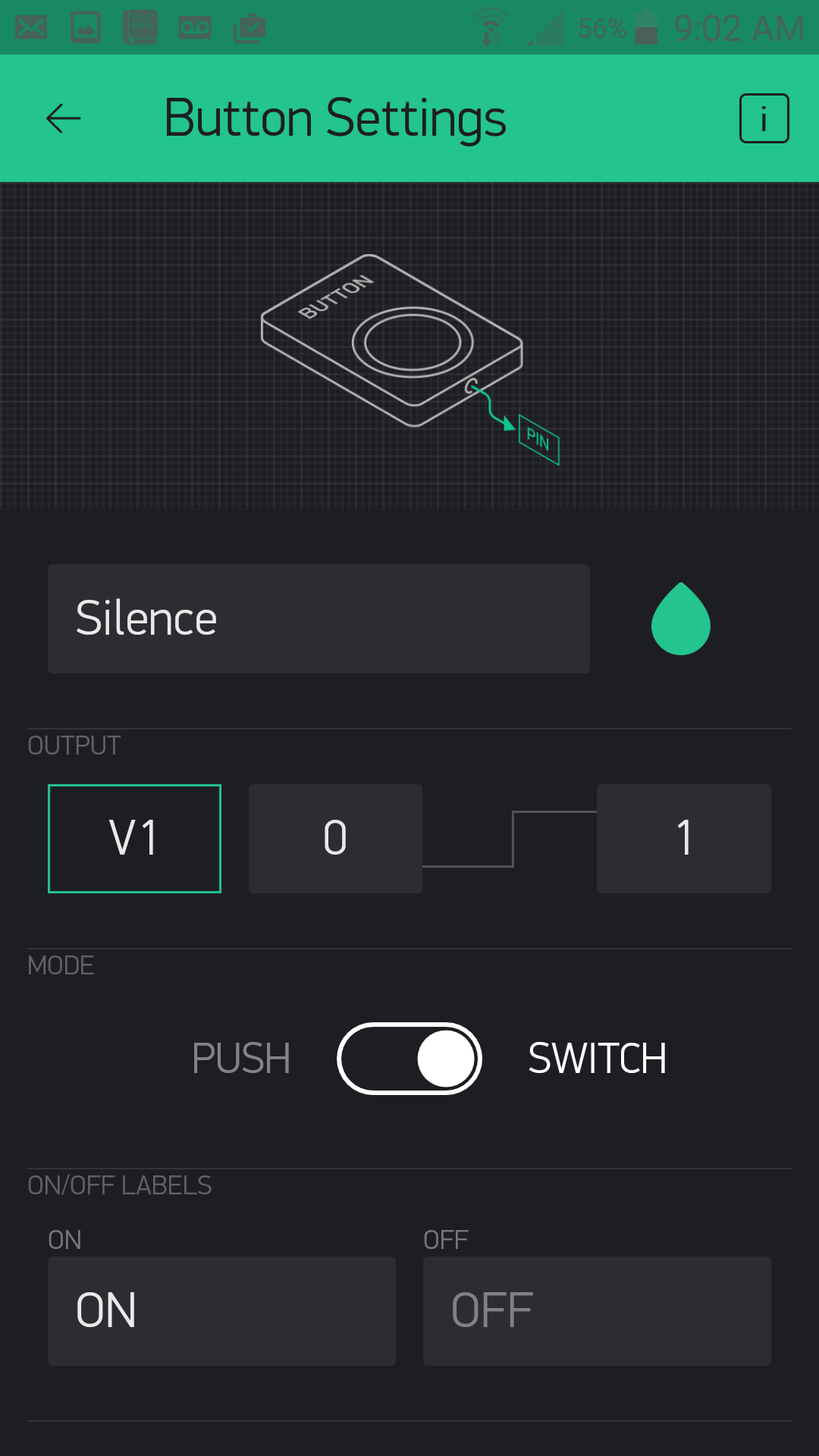
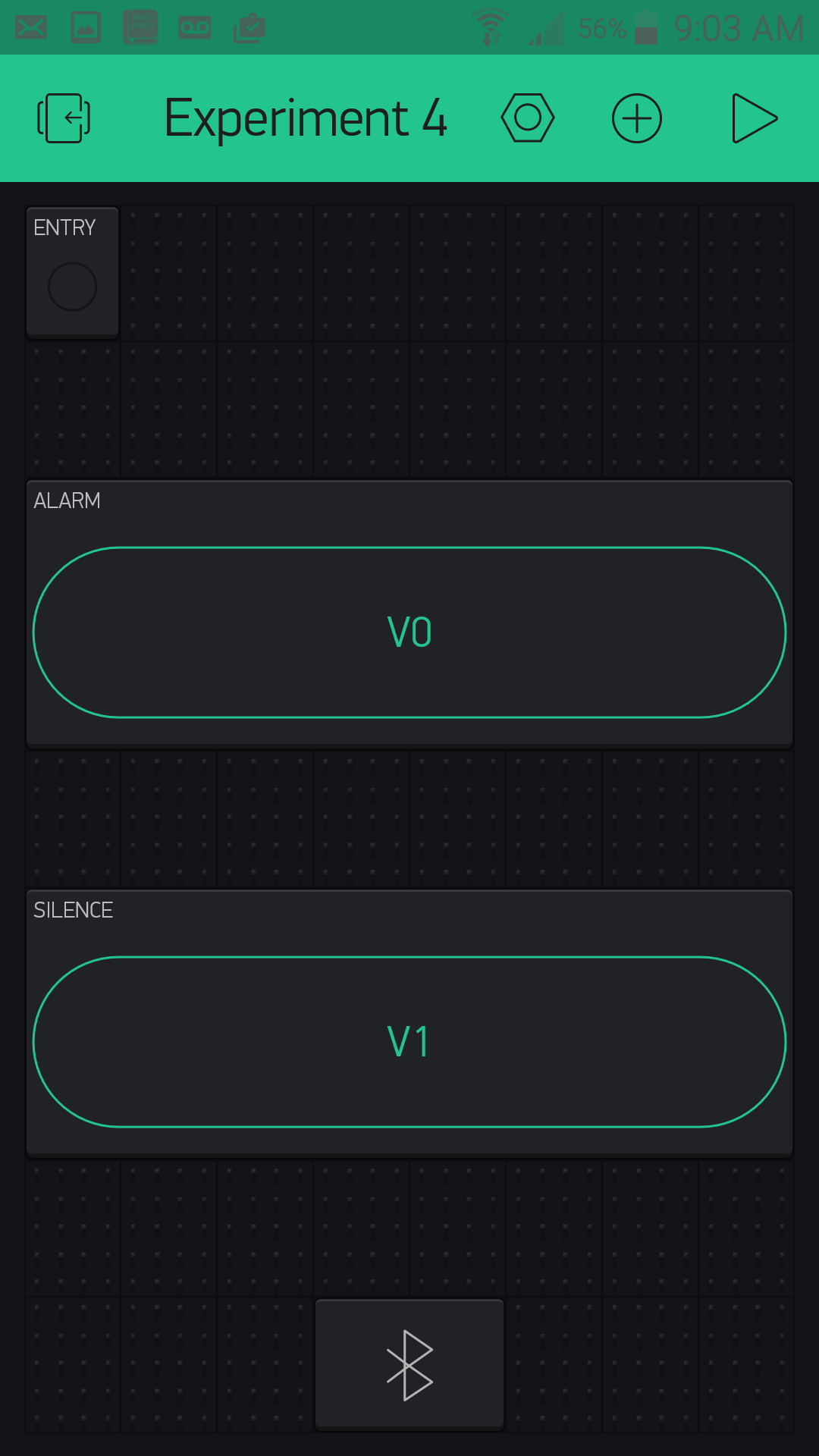
With that, your app should look something like this, maybe with a difference in placement and button colors.
Now, it's time to add the magic on the Arduino 101 end and complete your security system!
Upload Your Sketch
Let's get this code knocked out! Be sure to insert your authorization token into your sketch before you upload it; otherwise your app will not work with this code!
You can type out or copy and paste the following code into the Arduino IDE. Hit upload, and see what happens!
language:cpp
/********************************************************************************
SparkFun Around-The-Home SIK Expansion Kit, Experiment 4
SparkFun Electronics
Product URL

Builds a Blynk app controlled door burglar alarm where you can disarm / arm and mute the alarm from a Blynk app that reads a door switch.

This example is written by: Derek Runberg, Educational Technologist

This sketch was written by SparkFun Electronics, with lots of help from the Arduino community.
This code is completely free for any use.

View circuit diagram and instructions at:https://learn.sparkfun.com/tutorials/around-the-home-expansion-kit

********************************************************************************/

/* Comment this out to disable prints and save space */
#define BLYNK_PRINT Serial
#include <BlynkSimpleCurieBLE.h>
#include <CurieBLE.h>

BLEPeripheral  blePeripheral;


// You should get Auth Token in the Blynk App.
// Go to the Project Settings (nut icon).
char auth[] = "your auth token";

//create global constant for component pins
const int SENSOR_PIN = 7;
const int BUZZER_PIN = 6;

//create boolean variables for mute and armed options
boolean mute = false;
boolean armed = false;


void setup()
{
  Serial.begin(9600);
  blePeripheral.setLocalName("Exp_04");
  blePeripheral.setDeviceName("Exp_04");
  blePeripheral.setAppearance(384);

  Blynk.begin(blePeripheral, auth);

  blePeripheral.begin();

  //set BUZZER_PIN as OUTPUT for the buzzer
  pinMode(BUZZER_PIN, OUTPUT);
  //set SENSOR_PIN as INPUT_PULLUP for the door switch
  pinMode(SENSOR_PIN,INPUT_PULLUP);
}

void loop()
{
  int doorState = digitalRead(SENSOR_PIN);
  if(armed == true && doorState == 1){
    if(mute == true){
       noTone(BUZZER_PIN);
    }else{
      tone(BUZZER_PIN, 5000);
    }
  }
  else{
    noTone(BUZZER_PIN);
  }
  Blynk.run();
  blePeripheral.poll();
}

BLYNK_WRITE(V0)
{
  armed = !armed;
}

BLYNK_WRITE(V1)
{
  mute = !mute;
}
Code to Note
pinMode(SENSOR_PIN,INPUT_PULLUP);
To keep the wiring simple and not use a pullup resistor we used the INPUT_PULLUP constant as the pinMode. This internally pulls the pin high and removes the need for the resistor, but then causes the boolean logic of the door switch being open vs. closed.
language:cpp
BLYNK_WRITE(V0)
{
  armed = !armed;
}

BLYNK_WRITE(V1)
{
  mute = !mute;
}
We use two Blynk event functions that are connected to the app via the arm / disarm button and the mute button. We use those events to do nothing but toggle global variables of mute and armed. That way you can arm / disarm and mute the alarm system then disconnect the app and the system will function on its own and not rely on the connection of the app for any real time control.
int doorState = digitalRead(SENSOR_PIN);
We store the state of the door (opened = 1, closed=0) in a local variable called doorState using a simple digitalRead() function.
language:cpp
if(armed == true && doorState == 1){
    if(mute == true){
       noTone(BUZZER_PIN);
    }else{
      tone(BUZZER_PIN, 5000);
    }
  }
We use nested if statements to check the state of the door. If it is close and muted the buzzer is quiet. Else the buzzer sounds using the tone() command at 5000 Hz!
What You Should See
You should power up the circuit with the door switch mounted to the door, or whatever you are securing (cabinet, box, etc.). Make sure the door is closed and connect to your project through Blynk. When you open the app and run it, you should be able to arm the alarm and also set whether the alarm is silent or not. Leave it off for testing. Now, open the door. The alarm should go off, and the LED in your Blynk app should be blinking! You should be able to silence it from the Blynk app, as well as disarm the lock.
The great thing about this system is that when you manipulate the settings using the Blynk widgets your options are saved as variables on the Arduino 101 board, so you should be able to set the alarm and walk away.
Troubleshooting
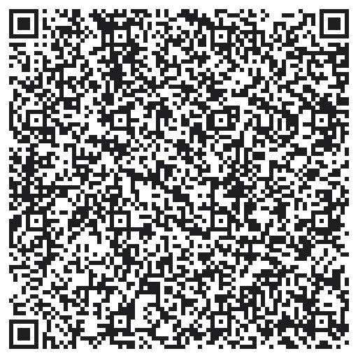
Blynk Shortcut
If you are having troubles duplicating the functionality above in the Blynk app, scan this QR code with Blynk to get a clone of this experiment!
Buzzer not buzzing
Double check your wiring to the buzzer. It is a polarized port and you may have it backwards, or the wires in your breadboard may not be aligned correctly.
Cannot toggle armed vs. disarmed
Make sure you are connected via BLE to your project and it shows up in your app. The Blynk app is the only way to disarm or mute the alarm system.
Experiment 5: Motion!
Introduction
OK, so you have detected the presence of an object, built a door security system, but what about detecting motion, the number one way we detect people? Enter the PIR (Passive Infrared) motion sensor! In this experiment you will look at how to use the PIR motion sensor to detect, well...motion. We will then put it to an interesting use other than to see whether something is moving or not.
The application of this sensor will be to build a pretty cool and colorful locking/latching system for a cabinet using the PIR motion sensor and an RGB with a servo from your Arduino 101 SIK with Blynk. Ready to go nuts? Yeah, we thought so!
Parts Needed
You will need the following parts:
- 1x Breadboard (From your Arduino 101 SIK)
- 1x Arduino 101 Board (From your Arduino 101 SIK)
- 1x PIR Motion Sensor
- 1x RGB LED Clear Common Cathode (From your Arduino 101 SIK)
- 3x 100 Ohm Resistor (From your Arduino 101 SIK)
- 14x Jumper Wires (From your Arduino 101 SIK)
- 1x Servo Motor (From your Arduino 101 SIK)
Didn't Get the Around-the-Home Expansion Kit?
If you are conducting this experiment and didn't get the Around-the-Home Expansion Kit, we suggest using these parts:


Arduino 101
DEV-13787Suggested Reading
Before continuing with this experiment, we recommend you be familiar with the concepts in the following tutorials:
- Light-Emitting Diodes --- Learn more about LEDs
- Switch Basics --- Learn more about buttons and switches
- Hobby Servo Tutorial --- Learn more about Servo motors
- PIR Motion Sensor Hookup Guide --- Take a deeper dive into the background of the PIR Motion Sensor
Introducing the PIR Motion Sensor
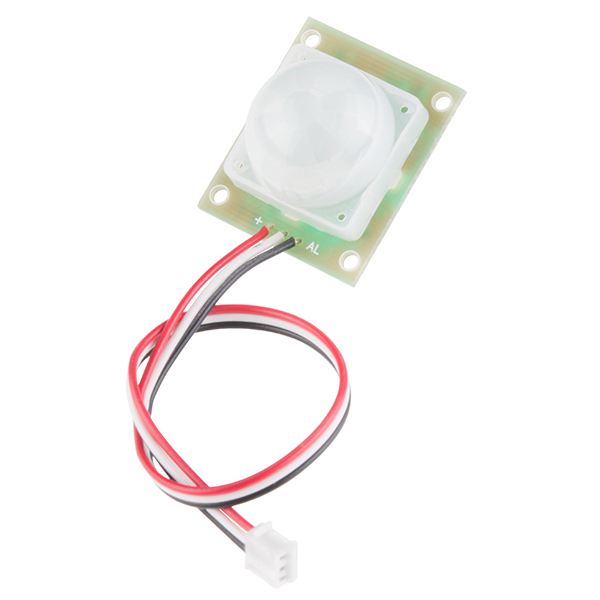
Passive infrared sensors are motion-detecting devices used in security systems across the world --- even though you may not see them, they probably see you!
Using the PIR sensor is simple: power it up, connect a pull-up resistor to the open-collector signal pin, and watch for it to go low. The PIR can sense abrupt changes in scenery as far as 10 feet (~3m) away. Once your microcontroller is sensing movement, it can trigger a buzzer, text message, tweet or klaxon.
Take a look at this Simple Circuit video to see the PIR Motion Sensor in action!
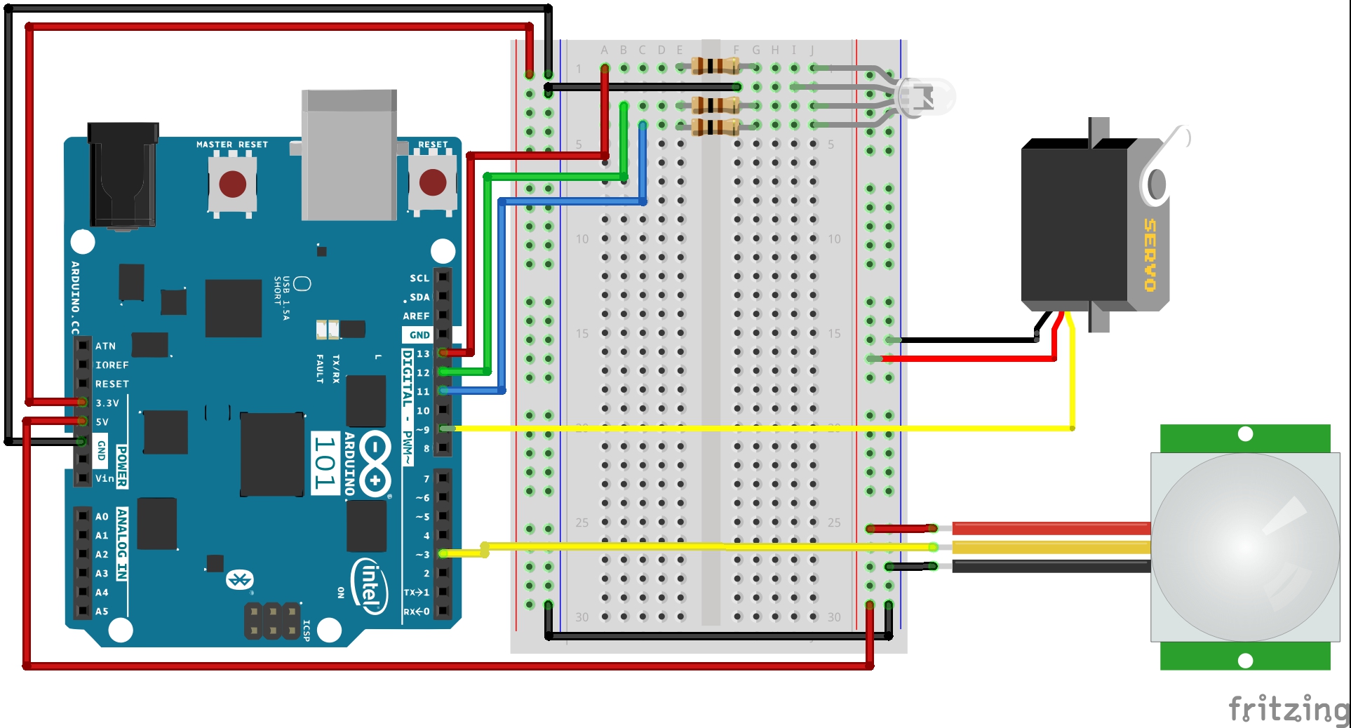
Hardware Hookup
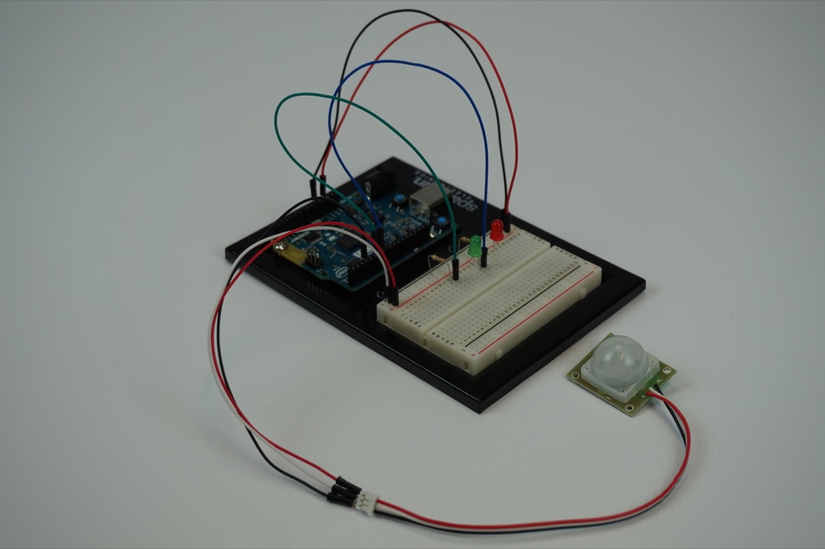
Ready to start hooking everything up? Check out the wiring diagram below to see how everything is connected.
Wiring Diagram for the Experiment
Build Your Blynk App
The Blynk app half of this project should be pretty straightforward for you. Again, be sure to create a new app in Blynk and check your email for the authorization token for your sketch.
As with all of the Blynk apps that use the Arduino 101 board, add the BLE widget and open the settings to connect your phone to the board.
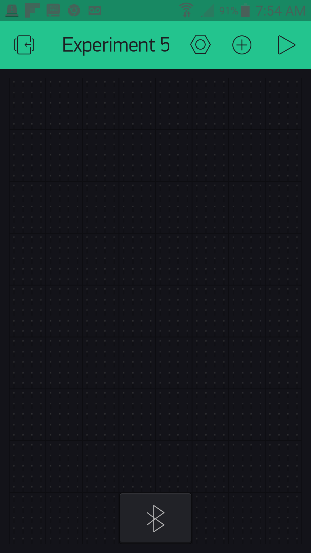
Once you have added the BLE widget, all you need to do is add three button widgets to your app and place/resize them to your taste.
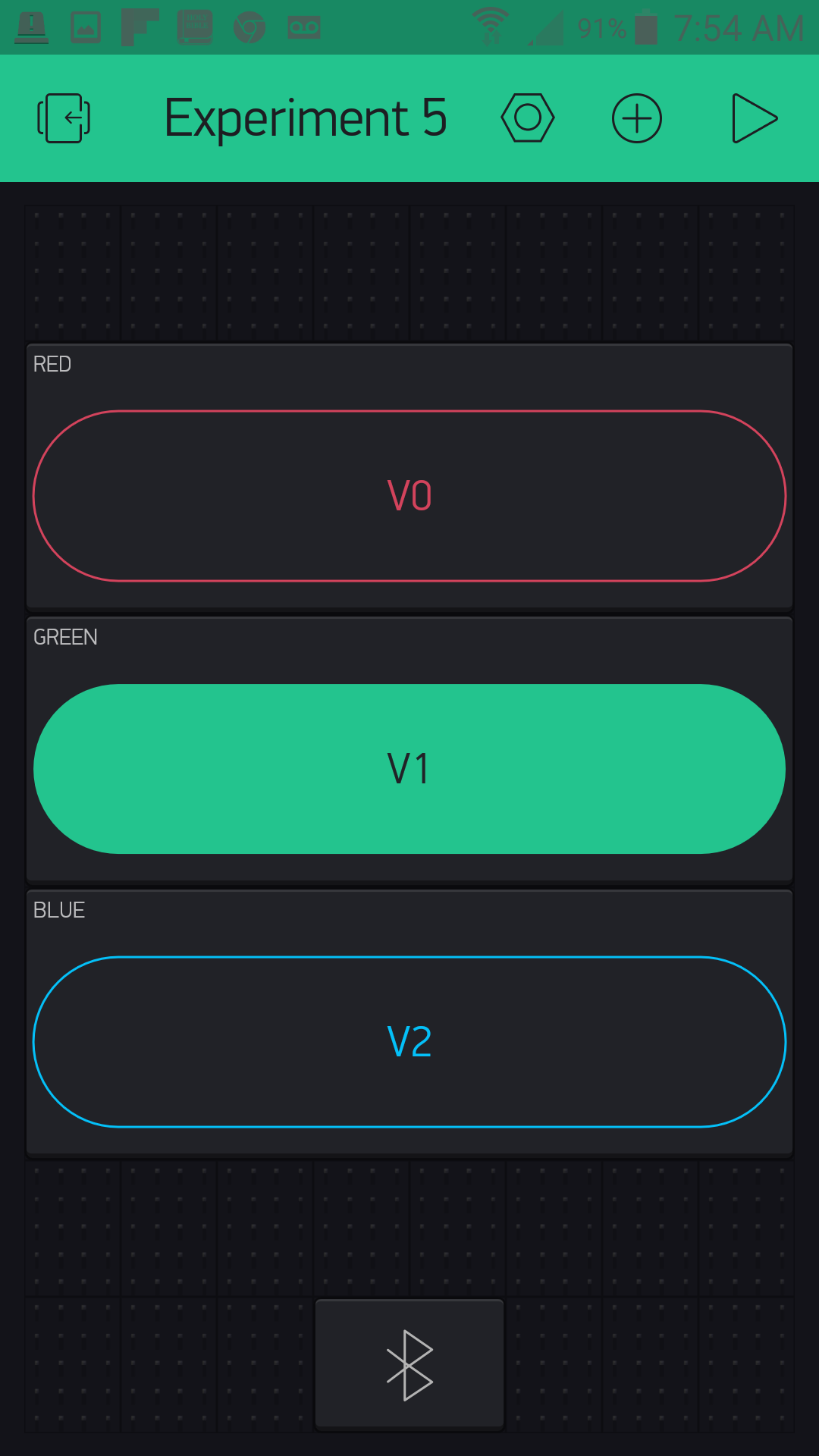
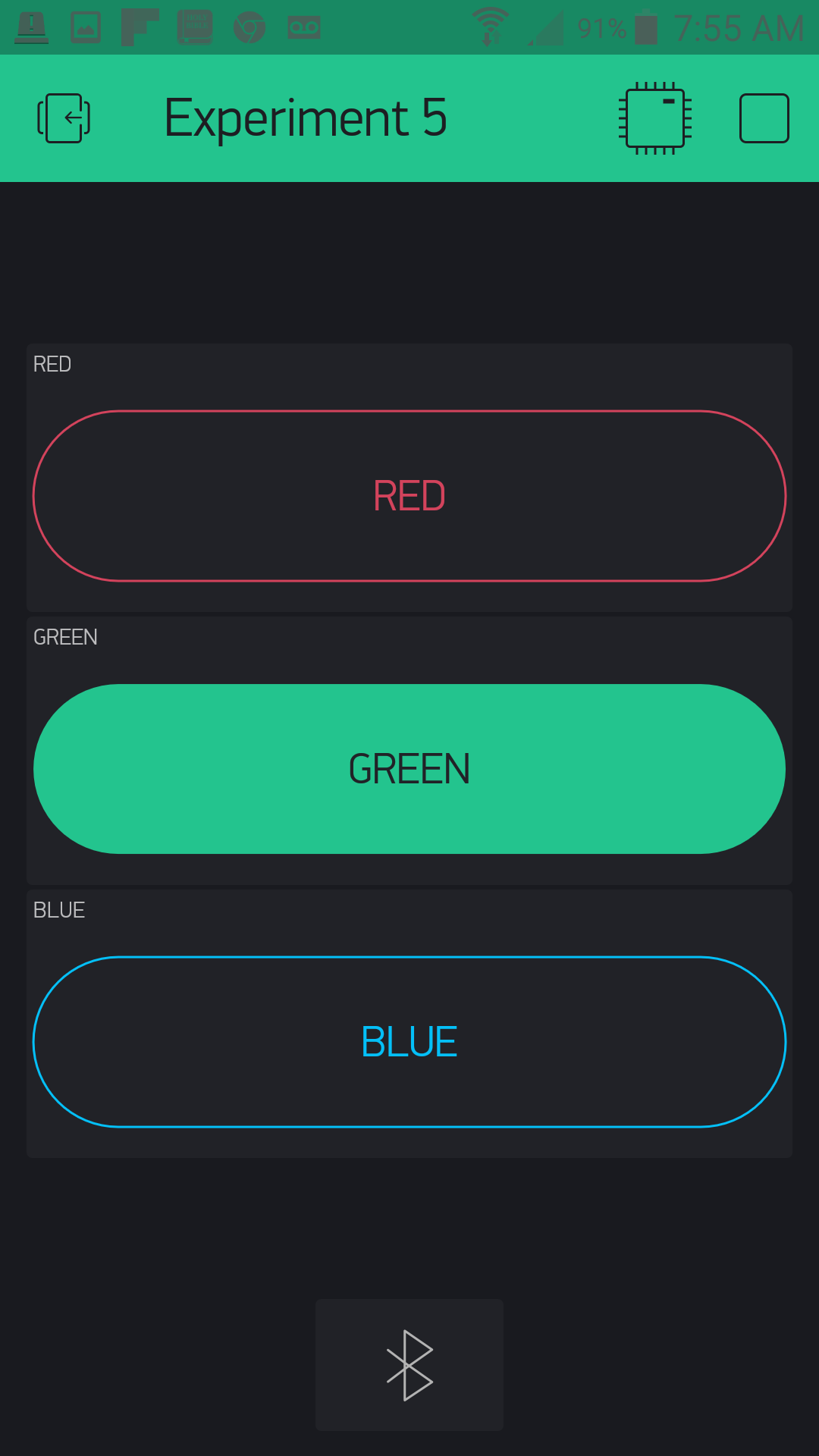
Each button will correspond to a color that you will see from the RGB LED (RED, GREEN and BLUE). We labeled each one accordingly and changed its color to match its name.
We then assigned each color a virtual pin to control. Here is what we used:
RED => Virtual Pin 0
GREEN => Virtual Pin 1
BLUE => Virtual Pin 2
The final task in setup of the buttons is to change each one to switch mode. This will keep the event from being triggered when you release the button and giving you a false value.
Here is what your completed RGB door key app should look like:
Uploading Your Sketch
Open the Arduino IDE software on your computer. Coding in the Arduino language will control your circuit.
You can type out or copy and paste the following code into the Arduino IDE. Hit upload, and see what happens!
language:cpp
/********************************************************************************
SparkFun Around-The-Home SIK Expansion Kit, Experiment 5
SparkFun Electronics
Product URL

Build a combination lock that detects when someone is present then displays a color on an RGB LED. The user has to input the color into a Blynk app to open a servo controlled latch.

This example is written by: Derek Runberg, Educational Technologist

This sketch was written by SparkFun Electronics, with lots of help from the Arduino community.
This code is completely free for any use.

View circuit diagram and instructions at:https://learn.sparkfun.com/tutorials/around-the-home-expansion-kit

********************************************************************************/

/* Comment this out to disable prints and save space */
#define BLYNK_PRINT Serial
#include <BlynkSimpleCurieBLE.h>
#include <CurieBLE.h>
#include <Servo.h>

Servo doorLatch;
BLEPeripheral  blePeripheral;


// You should get Auth Token in the Blynk App.
// Go to the Project Settings (nut icon).
char auth[] = "YOUR_AUTH_TOKEN";

const int RED_PIN = 13;
const int GREEN_PIN = 12;
const int BLUE_PIN  = 11;

const int MOTION_PIN = 3;
const int SERVO_PIN = 9;

int keyValue = 0;
int show;
boolean motion = false;

void setup()
 {
  Serial.begin(9600);
  blePeripheral.setLocalName("Exp_05");
  blePeripheral.setDeviceName("Exp_05");
  blePeripheral.setAppearance(384);

  Blynk.begin(blePeripheral, auth);

  blePeripheral.begin();

  // Set RGB LED pins as OUTPUT
  pinMode(13, OUTPUT);
  pinMode(12, OUTPUT);
  pinMode(11, OUTPUT);

  //set MOTION_PIN as INTPUT_PULLUP for motion sensor
  pinMode(MOTION_PIN, INPUT_PULLUP);

  //attach servo to SERVO_PIN
  doorLatch.attach(SERVO_PIN);

  //attach the interrupt to the motion pin
  attachInterrupt(MOTION_PIN, trigger, FALLING);
  doorLatch.write(10);
}

void loop()
{
  blePeripheral.poll();
  Blynk.run();

  if(motion == true){
    show = random(11,14);
    digitalWrite(show,HIGH);
    Serial.println(show);
    motion = !motion;
  }
}

//custom function called trigger
void trigger() {
  motion = !motion;
  detachInterrupt(MOTION_PIN);
}

BLYNK_WRITE(V0)
{
  keyValue = 0 + param.asInt(); // Get value as integer
  if (keyValue + show == 14) {
    doorLatch.write(90);
    digitalWrite(show, LOW);
    Serial.println("latch open");
    attachInterrupt(MOTION_PIN, trigger, FALLING);
  }
  else {
    keyValue = 0;
    doorLatch.write(10);
    Serial.println("latch closed");
  }
}

BLYNK_WRITE(V1)
{
  keyValue = 1 + param.asInt(); // Get value as integer
  if (keyValue + show == 14) {
    doorLatch.write(90);
    digitalWrite(show, LOW);
    Serial.println("latch open");
    attachInterrupt(MOTION_PIN, trigger, FALLING);
  }
  else {
    keyValue = 0;
    doorLatch.write(10);
    Serial.println("latch closed");
  }
}

BLYNK_WRITE(V2)
{
  keyValue = 2 + param.asInt(); // Get value as integer
  if (keyValue + show == 14) {
    doorLatch.write(90);
    digitalWrite(show, LOW);
    Serial.println("latch open");
    attachInterrupt(MOTION_PIN, trigger, FALLING);
  }
  else {
    keyValue = 0;
    doorLatch.write(10);
    Serial.println("latch closed");
  }
}
Code to Note
This Experiment uses a bunch of hardware from both the Expansion Kit and the SIK for the Arduino 101, and also presents a number of programming concepts to dive into using both Blynk and Arduino. Hope you have your programming hat on because here we go!
language:cpp
int keyValue = 0;
int show;
Most of the top half of the sketch you have seen before: setup of Blynk and the BLE setup. But, we create two global variables: one called keyVale, which we assign a value of 0, and the other called show, which will store which LED color we will be displaying to the person trying to unlock the latch.
attachInterrupt(MOTION_PIN,trigger,FALLING);
Interrupts are amazing things, but sometimes hard to wrap your mind around. Interrupts are a way of triggering a function when that pin acts a certain way. For example when a pin goes from HIGH to LOW, it is called FALLING. This all happens outside of the normal loop function, so things happen once and are not repeated over and over again as they would be if you used an if() statement in the loop. You pass the attachInterrupt() command three parameters: the pin number you are watching, the function you want triggered and finally the action it is watching for. Here are the actions you can look for:
FALLING--- Pin state going from HIGH to LOWRISING--- Pin state going from LOW to HIGHCHANGE--- Any pin state change
A couple words of warning when using interrupts...
- Never use delay() in an interrupt trigger function
- Try to keep the triggered function as short as possible
- Interrupts can only be used on certain pins depending on the Arduino you use; on the Arduino 101 board, you can use 0 through 12.
language:cpp
void trigger() {
  motion = !motion;
  detachInterrupt(MOTION_PIN);
 }
The trigger() function is the function that is triggered by the interrupt. All that it does is flip-flop the motion Boolean variable and then detach the interrupt so that it doesn't keep firing if you are standing in front of the motion sensor. That's it, nice and short...but some would argue that even this is too long.
language:cpp
  if(motion == true){
    show = random(11,14);
    digitalWrite(show,HIGH);
    Serial.println(show);
    motion = !motion;
  }
The if() statement that is inside of the loop tracks if motion is true or false. If it is true, it generates a random number and is stored inside of the show variable. We then turn on the pin that corresponds to that random number. Finally, the motion variable is flopped to false to keep the if() statement from firing on the next loop.
language:cpp
BLYNK_WRITE(V0)
{
 keyValue = 0 + param.asInt(); // Get value as integer
 if (keyValue + show == 14) {
   doorLatch.write(90);
   digitalWrite(show, LOW);
   Serial.println("latch open");
   }
 else {
   keyValue = 0;
   Serial.println("latch closed");
  }
 }
The Blynk app library for Arduino uses a number of special functions that are called event functions. Basically they are triggered through data being sent by the Blynk app. In this case, when a value is written to virtual pin V0, the contents of this function are triggered. Inside of this event function we read the data sent from the app as an integer using the param.asInt() method.
We add a value to it for each progressive pin number. We do this because we want to make sure that if the app user presses the correct color the keyValue + show should equal 14. We use an if() statement to check this math. If it does equal 14, then the "key" is correct, and the servo unlatches. If the "key" is incorrect, the servo stays latched, and the keyValue is reset. If you look at the full sketch, you can see that we have three different event functions for the three RGB colors and colored buttons in the app.
Basically, when you press the button that matches the color of the RGB LED, the servo moves.
What You Should See
When you move in front of the PIR motion sensor the Arduino 101 board will generate a random color of the RGB LED. If you connect to the Blynk app over BLE and press the button that corresponds to the color of the RGB LED, the servo will "unlock" or move to the 90-degree position. To "lock" the servo again press the same color again, this should also put the 101 back in a state of watching for motion to display a color again!
Troubleshooting
Blynk Shortcut!
If you are having troubles duplicating the functionality above in the Blynk app, scan this QR code with Blynk to get a clone of this experiment!
Program Not Uploading
This happens sometimes; the most likely cause is a confused serial port. You can change this in Tools > Serial Port >
Also, if you get a Timeout error or the IDE could not find your 101 board, try pressing the Master Reset button on the 101, wait around 10 seconds and try re-uploading your sketch.
Still No Success
A broken circuit is no fun. Send us an email, and we will get back to you as soon as we can: techsupport@sparkfun.com
Experiment 6: Controlling a Solenoid Valve With a MOSFET
Introduction
A big part of home automation is being able to control devices and circuits that operate at a lot higher voltage and current than a standard microcontroller. If you hooked up the GPIO pin of an Arduino 101 board to 12 volts, you would destroy your board. So, how is it done?
The answer is using something called a MOSFET! In this experiment we will use the Arduino 101 and Blynk to control a solenoid valve using a MOSFET and build a BLE-controlled sprinkler timer! Hope you brought your swimsuit because you are going to need it!
Parts Needed
You will need the following parts:
- 1x Breadboard (From your Arduino 101 SIK)
- 1x Arduino 101 Board (From your Arduino 101 SIK)
- 1x MOSFET
- 1x Solenoid Valve
- 2x Female Disconnects
- 1x 12V Wall Wart Power Adapter
- 2x 10k Ohm Resistor (From your Arduino 101 SIK)
- 8x Jumper Wires (From your Arduino 101 SIK)
Didn't Get the Around-the-Home Expansion Kit?
If you are conducting this experiment and didn't get the Around-the-Home Expansion Kit, we suggest using these parts:
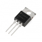
N-Channel MOSFET 60V 30A
COM-10213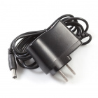
Wall Adapter Power Supply - 12VDC 600mA
TOL-09442
Arduino 101
DEV-13787Suggested Reading
Before continuing with this experiment, we recommend you be familiar with the concepts in the following tutorials:
- Light-Emitting Diodes --- Learn more about LEDs
- Switch Basics --- Learn more about buttons and switches
Introducing the MOSFET
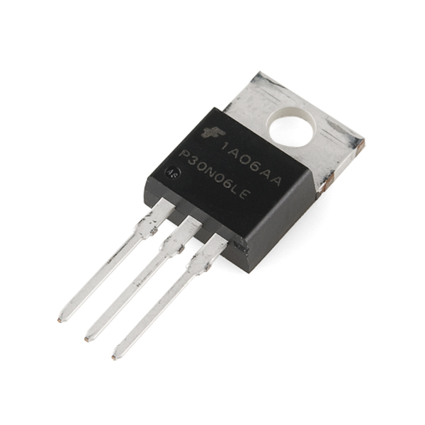
In Experiment 11 from the SparkFun Inventor's Kit for the Arduino 101 experiment guide, you learned about using transistors and that they were like a switch that allows you to control larger loads of electricity with a much smaller current and/or voltage in a safe way, protecting your Arduino board from harm. A MOSFET does the same thing, and, in fact, we are using them the same way. They are hooked up differently, and the MOSFET can handle a much larger load than the puny transistor from your Inventor's Kit.
Similar to the transistor, the MOSFET has three legs, but they have different names. If you place the MOSFET on the table with its flange side down and the legs pointing toward you, the pins are named as follows:
LEFT = Gate
MIDDLE = Drain
RIGHT = Source
Here is a reference image from the datasheet of the MOSFET we use in this kit:
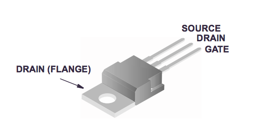
To use the MOSFET you connect the Gate pin to a GPIO pin of a microcontroller --- in this case, your Arduino 101 board. The Drain is connected to the load's ground line, and the Source is connected to the system's Ground. When you energize, or pull the Gate HIGH, you let current through the MOSFET in through the Drain and out through the Source.
Thank you, Pete! Now back to your regularly scheduled programming!
Introducing the Solenoid Valve
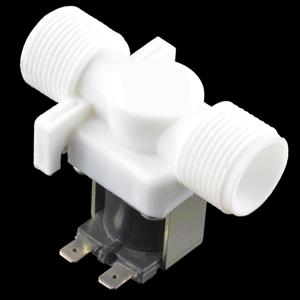
Have you ever wanted to control the flow of a liquid using your computer or microcontroller? Yeah, us too! Well, here’s how: This is a 12V solenoid-controlled fluid valve. Simply connect a fluid source to the ¾" threaded inlet, and it will interrupt the flow until 12V is applied to the fast-on connectors on the solenoid.
By now you are probably connecting the dots as to why we also covered the MOSFET in that this valve functions using 12 volts, much too high to run through the GPIO pins of the Arduino 101 board. So, we will control this valve using the MOSFET and a 12V wall power supply.
When you connect this valve to 12 volts and Ground, the coil inside of it gets energized and pulls the valve open, allowing water that is under pressure to flow through it. Yep, that's right; for this valve to work, the water you are controlling needs to be under pressure. Not a problem for our application, as we are going to be building a sprinkler timer.
Connecting the Valve
"But, wait!" you may be asking, "How do I connect the valve to the rest of my circuit with those funny tabs?" Great question! We have included female disconnects that are pretty easy to add to jumper wires if you have a pair of pliers. Grab two jumper wires, two disconnects and your pliers, and let's build some custom jumper wires!
First start by sliding the female disconnect over one end of a jumper wire and press it as far as it will go. Then take your plier and crimp the disconnect onto the wire as hard as you can. We don't want the disconnect coming loose!
OK, that's it! Rinse and repeat for the second wire, and you should be good to go! Give your new disconnects a good test to make sure they will stay on the wire, and let's jump to the next steps.
Hardware Hookup
Ready to start hooking everything up? Check out the wiring diagram below to see how everything is connected.
Wiring Diagram for the Experiment
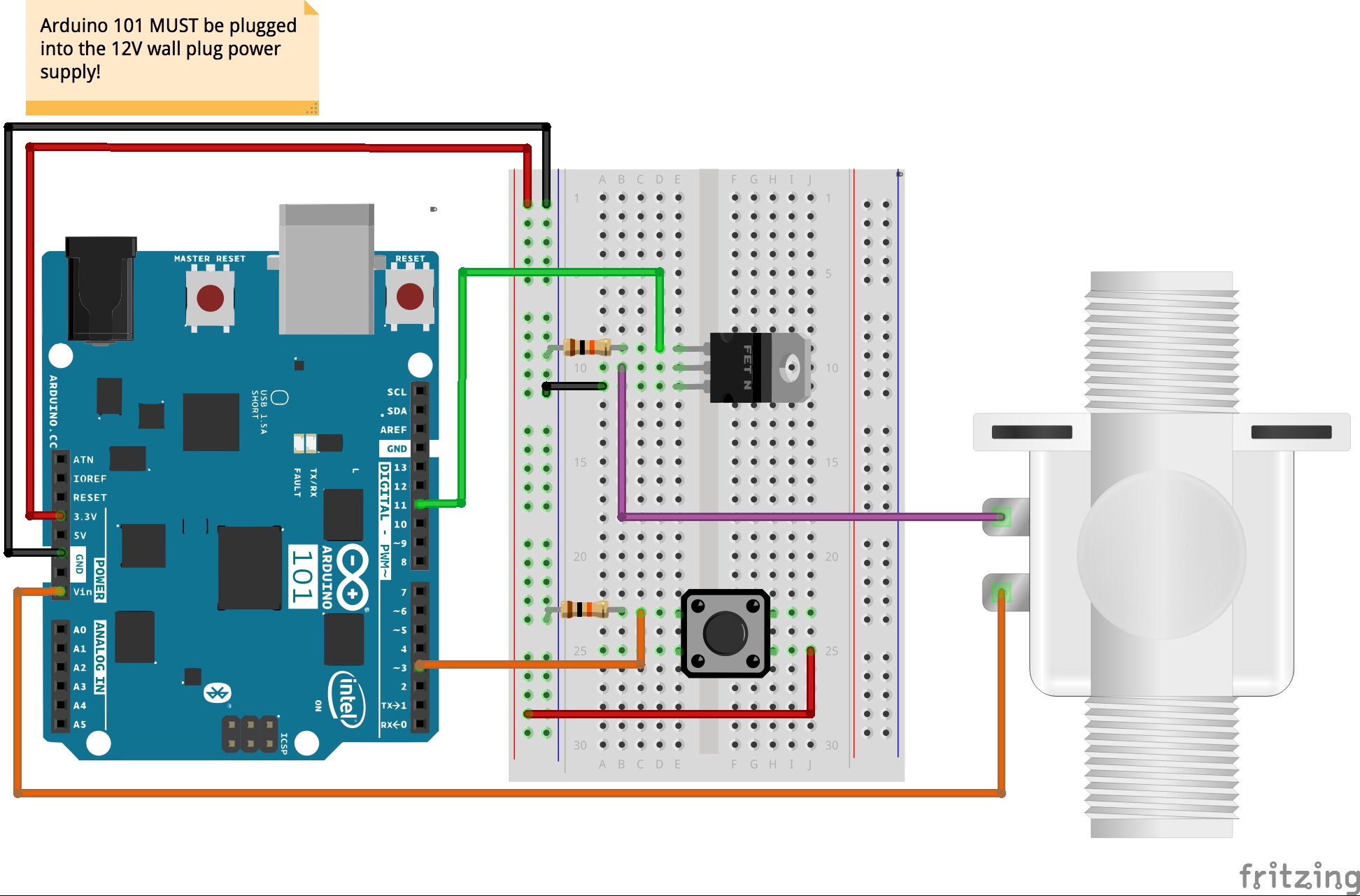
Powering Your Project
When you start to build projects that use either higher current or voltage levels that exceed the standard operational levels that the Arduino 101 board can source from a USB cable, an alternative power supply will be needed. In fact, you have probably been dangerously close using the BLE and controlling circuits in the past four experiments.
In this case, we are using a solenoid valve that requires 12V to operate. The good thing is that the Arduino 101 board can be powered by an external power supply in the range of 7 to 14 volts through the barrel jack on the board. This kit includes a 12V power supply just for this reason!
Once you plug the Arduino 101 board into the 12V power supply, it will turn the board on, and you will have access to both the 5V and 3.3V power rails. But now your VIN pin will be 12V, and you can use that pin to power your solenoid!
Build Your Blynk App
This Blynk app is a little more complicated than in your previous projects. You will be using the Time Input widget to set the Real-Time Clock (RTC) on the Arduino 101 board. For more details on that, or a quick refresher, you can reference Experiment X of the SIK guide for the Arduino 101 board. This app will allow you to set the RTC and then set a timer to control the solenoid valve to open and close at given time intervals to water your favorite tomato plant --- or to control a water feature in your backyard.
This capitalizes on the internal memory and global variables so that you can connect to your project, set the times, disconnect and not worry about it.
As with all of the Blynk apps that use the Arduino 101 board, add the BLE widget and open the settings to connect your phone to the board.
Once you have added the BLE widget, we will add two different Time Input widgets. These widgets allow for you to set the time and create timers that schedule functions to happen at given times. We will first add both Timer Input widgets to your app. These cannot be resized, so place them in a way that makes sense to you.

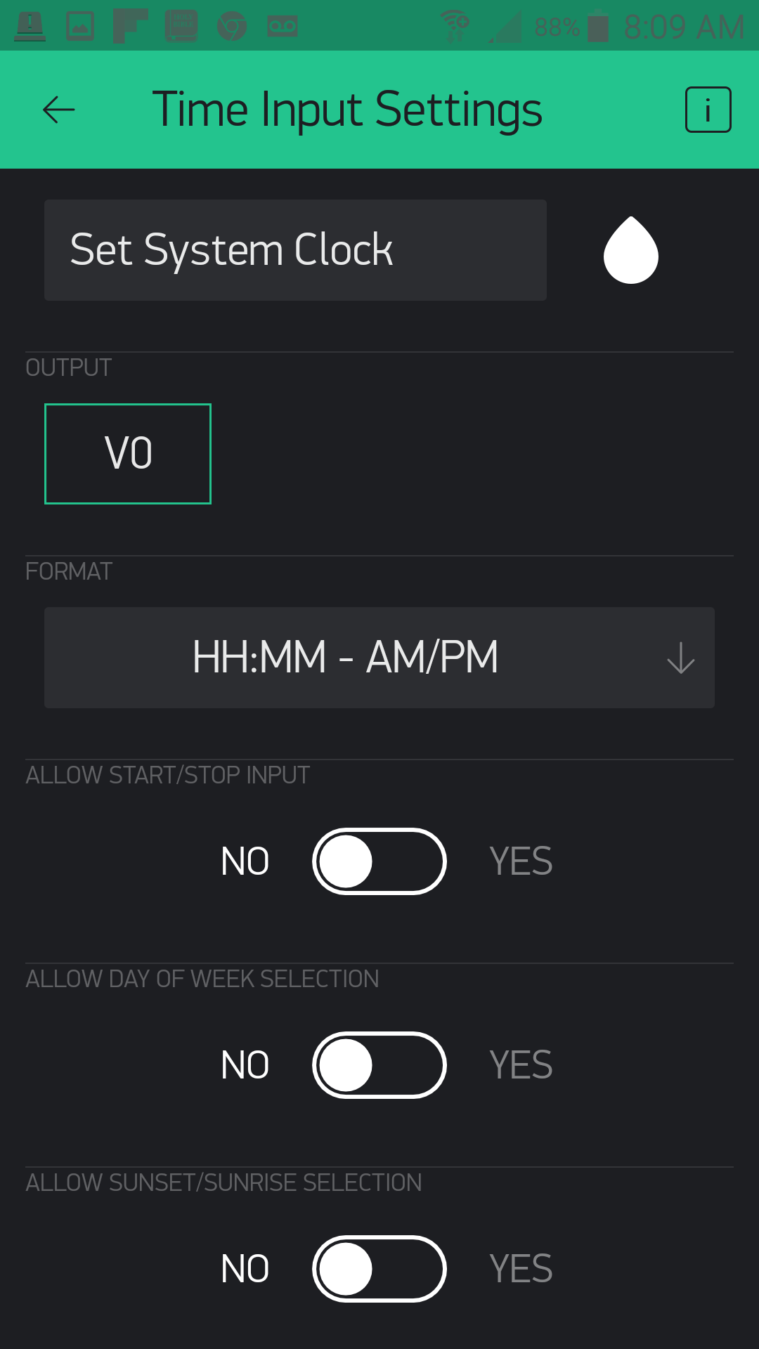
Open one of the Time Input widgets and name it "Set System Clock" and its output to pin V0. Set the format as "HH:MM - AM/PM". We changed no other setting after that. This input is what you will use to set the RTC to your current time. You will need to do this any time that your 101 loses power, or is reset.
Open the second Time Input widget. This will be the timer control input. We labeled ours "Control Timer" and set the output to pin V1 with the format as "HH:MM". The only other setting we changed was to allow Start and Stop times.

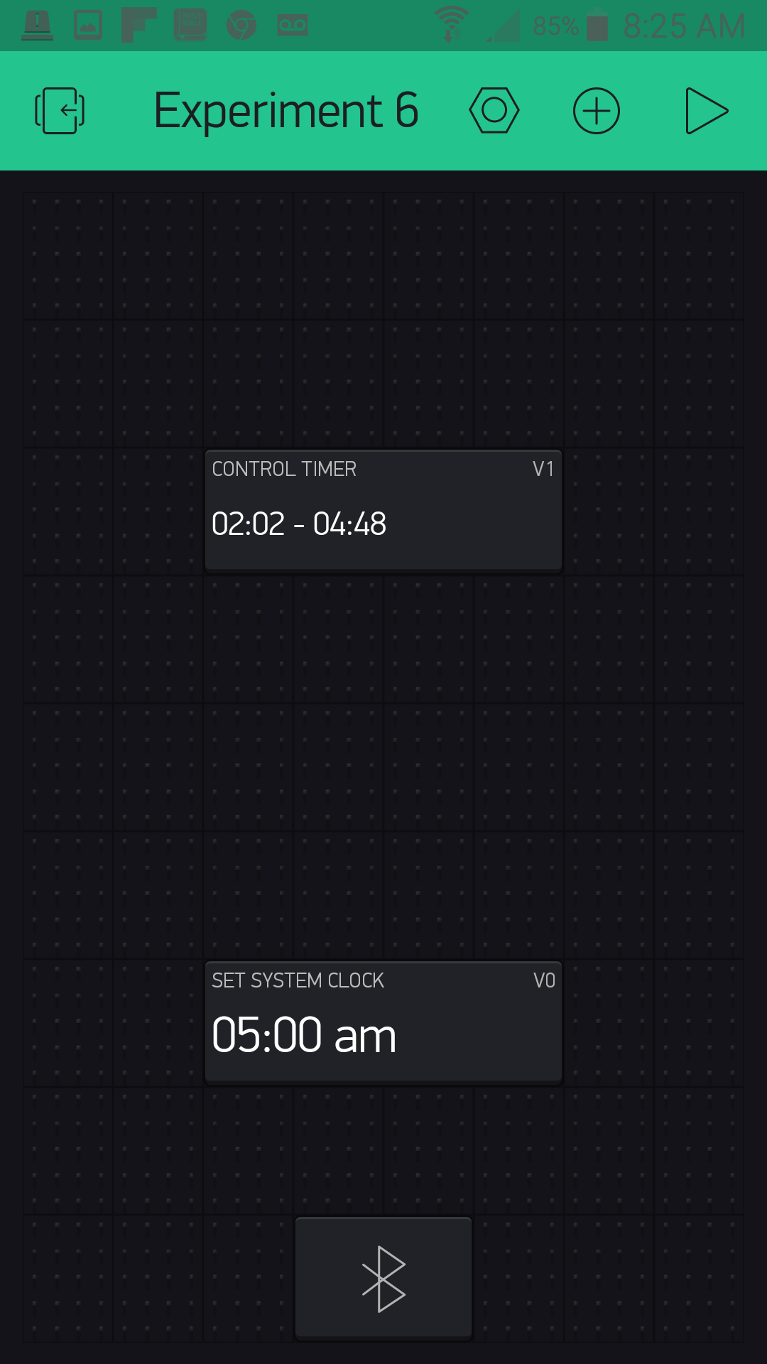
That's it! Your completed app should look something like this when you run it:
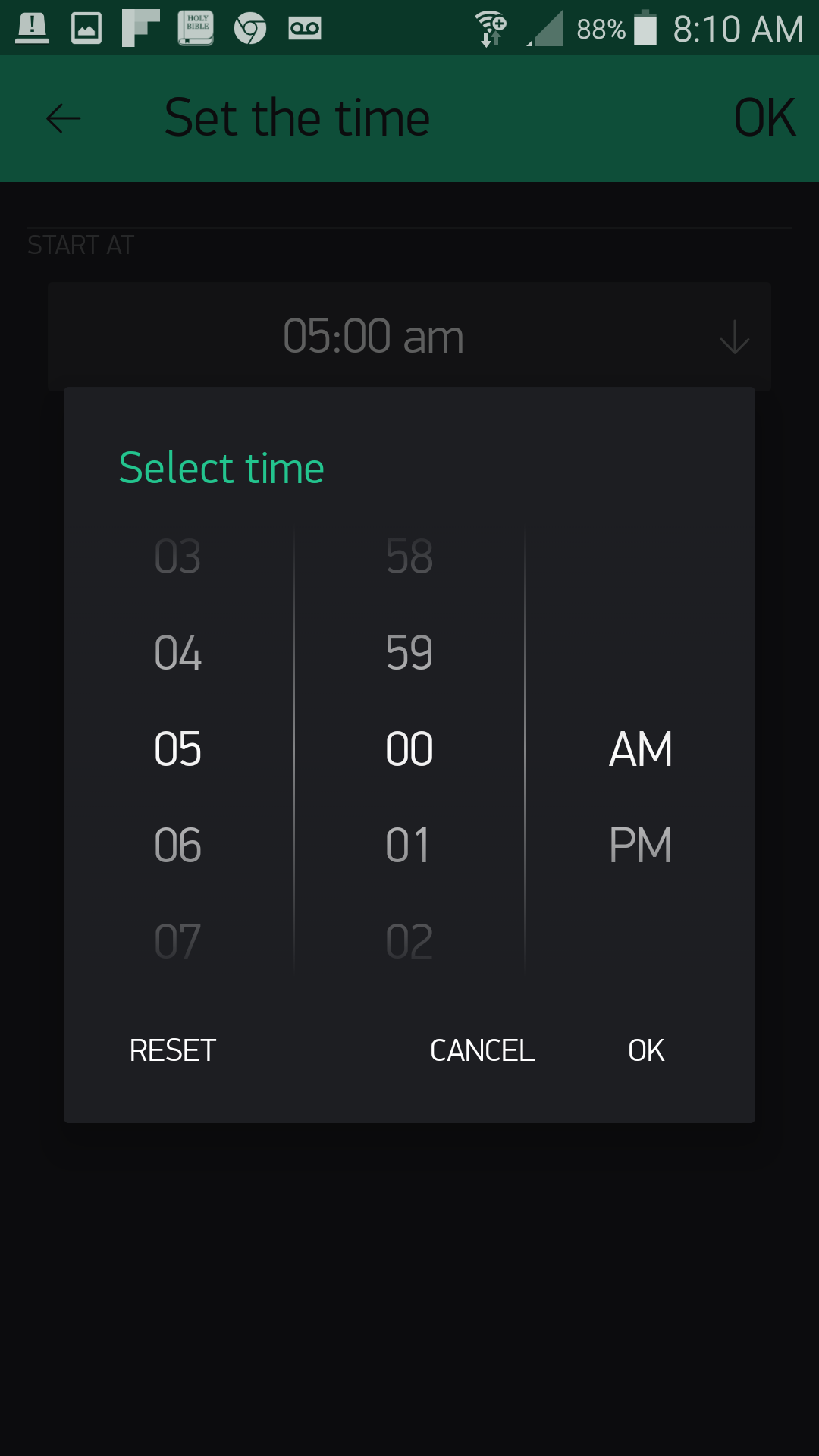
When you click on your "Set System Clock" it will allow you to set the time as shown below.
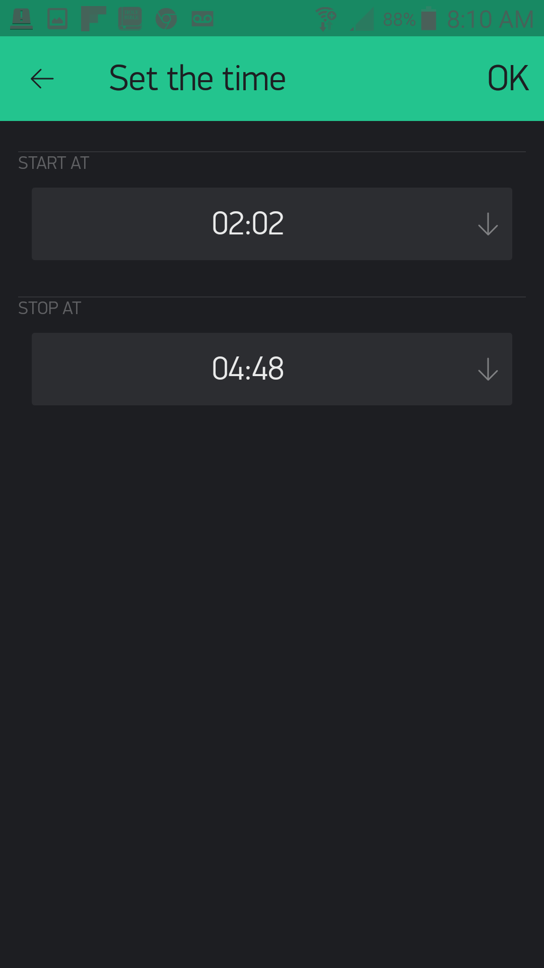
Your control timer interface will look something like this:
Now, let's get the Arduino sketch uploaded so that you won't have to worry about watering your lawn tomorrow.
Upload Your Sketch
Open the Arduino IDE software on your computer. Coding in the Arduino language will control your circuit.
You can type out or copy and paste the following code into the Arduino IDE. Hit upload, and see what happens!
language:cpp
/********************************************************************************
SparkFun Around-The-Home SIK Expansion Kit, Experiment 6
SparkFun Electronics
Product URL

Set the time of the Real-time-clock on the Arduino 101 using Blynk then set a timer to control a solenoid valve to control your sprinkers.

This example is written by: Derek Runberg, Educational Technologist

This sketch was written by SparkFun Electronics, with lots of help from the Arduino community.
This code is completely free for any use.

View circuit diagram and instructions at:https://learn.sparkfun.com/tutorials/around-the-home-expansion-kit

********************************************************************************/

/* Comment this out to disable prints and save space */
#define BLYNK_PRINT Serial
#include <CurieTime.h>
#include <BlynkSimpleCurieBLE.h>
#include <CurieBLE.h>

BLEPeripheral  blePeripheral;

// You should get Auth Token in the Blynk App.
// Go to the Project Settings (nut icon).
char auth[] = "YOUR_AUTH_TOKEN";


int startHour, startMinute, stopHour, stopMinute;
int override = false;

const int BUTTON_PIN = 3;
const int VALVE_PIN = 11;

void setup()
{
  Serial.begin(9600);

  blePeripheral.setLocalName("Exp_06");
  blePeripheral.setDeviceName("Exp_06");
  blePeripheral.setAppearance(384);

  pinMode(BUTTON_PIN, INPUT);
  pinMode(VALVE_PIN, OUTPUT);
  Blynk.begin(blePeripheral, auth);

  blePeripheral.begin();
  attachInterrupt(3,testValve,CHANGE);
}

void loop()
{
    //if start time matches...
    if (hour() == startHour && minute() == startMinute) {
      digitalWrite(VALVE_PIN, HIGH);
    }
    //if stop time matches...
    if (hour() == stopHour && minute() == stopMinute) {
      digitalWrite(VALVE_PIN, LOW);
    }
  blePeripheral.poll();
  Blynk.run();
}

void testValve(){
  if(digitalRead(BUTTON_PIN) == HIGH){
    digitalWrite(VALVE_PIN, HIGH);
    Serial.println("test fire");
  }
  else{
    digitalWrite(VALVE_PIN, LOW);
  }
}

//set clock event
BLYNK_WRITE(V0) {
  TimeInputParam t(param);

  // Set the RTC on the Arduino 101
  setTime(t.getStartHour(), t.getStartMinute(), 0, 2, 2, 2015);
}

//event function for timer
BLYNK_WRITE(V1) {
  TimeInputParam t(param);

  // Process start time
  if (t.hasStartTime())
  {
    startHour = t.getStartHour();
    startMinute = t.getStartMinute();
  }

  // Process stop time
  if (t.hasStopTime())
  {
    stopHour = t.getStopHour();
    stopMinute = t.getStopMinute();
  }
}
Code to Note
#include <CurieTime.h>
The Arduino 101 board, and specifically the Intel® Curie chip that is on the board, has its own Real-Time Clock (RTC), which we end up using in this project. To interact with the RTC, we need to add the CurieTime library that is included with Arduino when you install the Arduino 101 board definitions.
int startHour, startMinute, stopHour, stopMinute;
We create a number of empty global variables to start with in a bit of a different way. If you are going to create a number of variables of the same data type, you can actually list them out separated by commas in this fashion.
language:cpp
const int BUTTON_PIN = 3;
const int VALVE_PIN = 11;
We created two global constants to store the pin numbers for each component.
language:cpp
//set clock event
BLYNK_WRITE(V0) {
  TimeInputParam t(param);

  // Set the RTC on the Arduino 101
  setTime(t.getHour, t.getMinute, t.getSecond, 2, 2, 2015);
}
When you input a time into the Clock Set widget in your app, that time is written to the virtual pin 0 or V0. We then create a TimeInputParam object called t. We then set the RTC of the Arduino 101 board using the setTime() function and pass it the time parameters from t.
language:cpp
     //if start time matches...
     if(hour() == startHour && minute() == startMinute){
     digitalWrite(VALVE_PIN,HIGH);
    }
     //if stop time matches...
     if(hour() == stopHour && minute() == stopMinute){
     digitalWrite(VALVE_PIN,HIGH);
   }
We use a series of if() statements to check against the current time and the start time variables captured from the start and stop time values received over pin V1 from the Control Timer widget and stored in the global start and stop variables.
language:cpp
 BLYNK_WRITE(V1) {
  TimeInputParam t(param);

  // Process start time
  if (t.hasStartTime())
  {
   startHour = t.getStartHour();
   startMinute = t.getStartMinute();
  }

 // Process stop time
 if (t.hasStopTime())
 {
  stopHour = t.getStopHour();
  stopMinute = t.getStopMinute();
 }
}
We capture the start and stop times over virtual pin V1 from the Control Timer widget. We again create a local TimeInputParam object, which holds the time data from pin V1. Then, using a series of if() statements checking for a start and stop time, we store those start and stop times in our global variables.
What You Should See
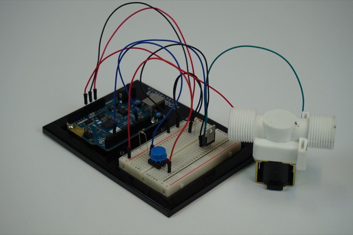
You shouldn't actually see anything happen right away. If you press down on the button in the circuit, which is the manual override, it should open the valve. If you press the button again, the valve will close.
If you connect to the Blynk app, you can set the Real-Time Clock on the Arduino 101 board, as well as a scheduled start and stop time. Set the time for your local time and then a start time about three minutes or so from that time, with a stop time five minutes later. From here you should be able to close the Blynk app as long as the Arduino 101 board stays powered up. You can do this because the Real-Time Clock on the Arduino 101 was set by the Blynk app, and all of the control logic for the watering system is on the Arduino side of the sketch.
The valve should turn on in three minutes and then off again in five more! No more forgetting that your sprinklers are running!
Troubleshooting
Blynk Shortcut!
If you are having troubles duplicating the functionality above in the Blynk app, scan this QR code with Blynk to get a clone of this experiment!
Program Not Uploading
This happens sometimes; the most likely cause is a confused serial port. You can change this in Tools > Serial Port >
Also, if you get a Timeout error or the IDE could not find your 101 board, try pressing the Master Reset button on the 101, wait around 10 seconds and try re-uploading your sketch.
Still No Success
A broken circuit is no fun. Send us an email, and we will get back to you as soon as we can: techsupport@sparkfun.com
Experiment 7: Moisture Sensor
Introduction
In this experiment, you'll use the SparkFun soil moisture sensor to alert you when your plants are getting sad and need a bit of water to cheer up, or if your watering system in Experiment 6 is going on the fritz.
Remember Experiment 3? In that experiment, you built a voltage divider circuit to read light intensity data as voltage from a photoresistor. Good news: the SparkFun moisture sensor has an onboard voltage divider --- it does that part for you! All you need to do is power it and read the analog values coming from its signal (third) pin.
We will use that voltage reading to detect the level of moisture in the soil (as water conducts electricity) and build a dashboard for your most coveted house plant. Hope you have your green thumb ready!
Suggested Reading
The following tutorials provide in-depth background on some of the hardware concepts in this experiment:
Parts Needed
You will need the following parts for this experiment:
- 1x Arduino 101 Board (From your Arduino 101 SIK)
- 1x Breadboard (From your Arduino 101 SIK)
- 1x Soil Moisture Sensor
- 5x Jumper Wires (From your Arduino 101 SIK)
- 1x Pocket Screw Driver (Not Included)
Didn't Get the Around-the-Home Expansion Kit?
If you are conducting this experiment and didn't get the Around-the-Home Expansion Kit, we suggest using these parts:
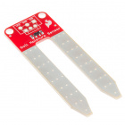
Headers or No Headers?
Note:If you are buying the breakout boards (Moisture Sensor) seperate from this kit you will also need to buy screw terminals and assemble (solder) them to your board yourself.
Arduino 101
DEV-13787Introduction to the Soil Moisture Sensor

The SparkFun Soil Moisture Sensor is a simple breakout board for measuring the moisture in soil and similar materials. The soil moisture sensor is straightforward to use. The two large, exposed pads function as probes for the sensor, together acting as a variable resistor. The more water that is in the soil, the better the conductivity between the pads will be, which will result in a lower resistance and a higher SIG (output voltage).
To get the SparkFun Soil Moisture Sensor functioning, all you need to do is connect the VCC and GND pins to your Arduino 101. You will receive a SIG out, which you will read using an Analog Input pin (A0), which will depend on the amount of moisture in the soil. Oh, and you'll also need a bit of dirt in a pot to test it all out!
One commonly known issue with soil moisture sensors is their short life span when exposed to a moist environment. To combat this, we've had the PCB coated in Gold Finishing (ENIG, or Electroless Nickel Immersion Gold), which will extend the life of your sensor.
->
Hardware Hookup
Ready to start hooking everything up? Check out the wiring diagram below to see how everything is connected.
Wiring Diagram for the Experiment
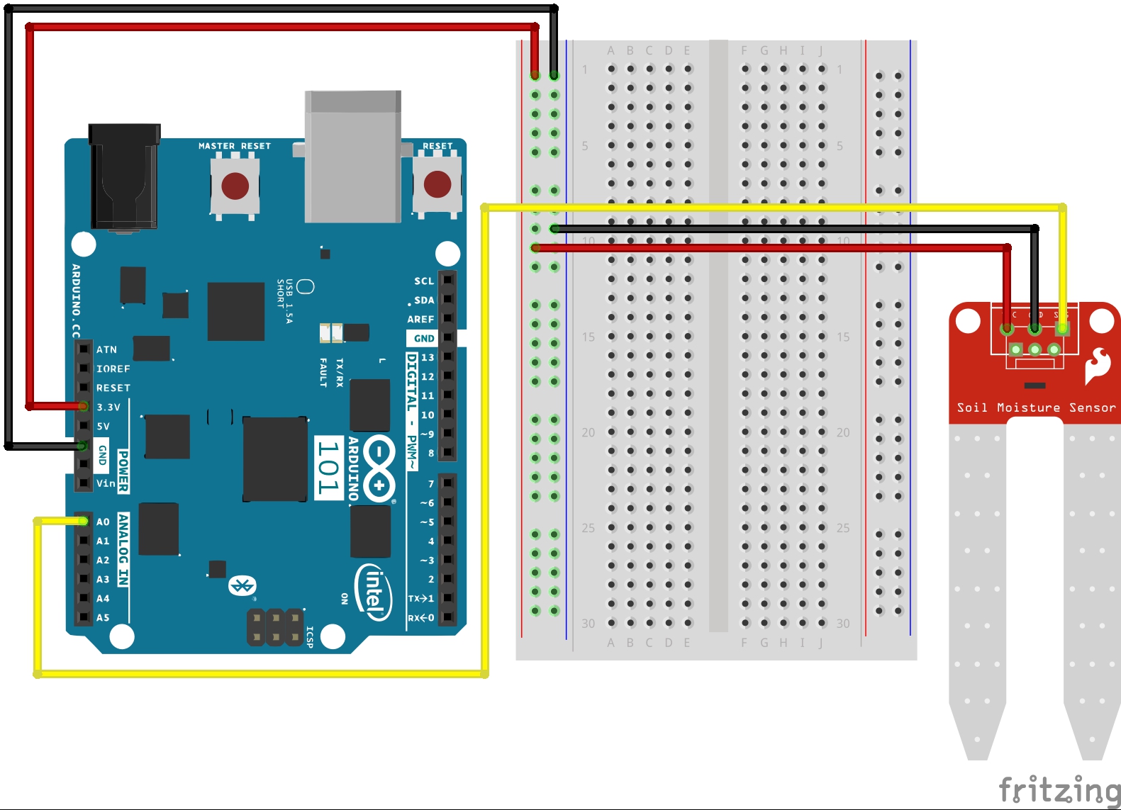
Build Your Blynk App
The Blynk app half of this project should be pretty straightforward for you, but it is good experience using the LCD widget and writing data to it. Again, be sure to create a new app in Blynk and check your email for the authorization token for your sketch.
As with all Blynk apps when you are using the Arduino 101, be sure to add the BLE widget into your app and make sure Bluetooth and Location are turned on for your phone.
Next add the LCD widget and place it wherever you like. We centered ours, as it will be the only widget other than the BLE one on the screen.
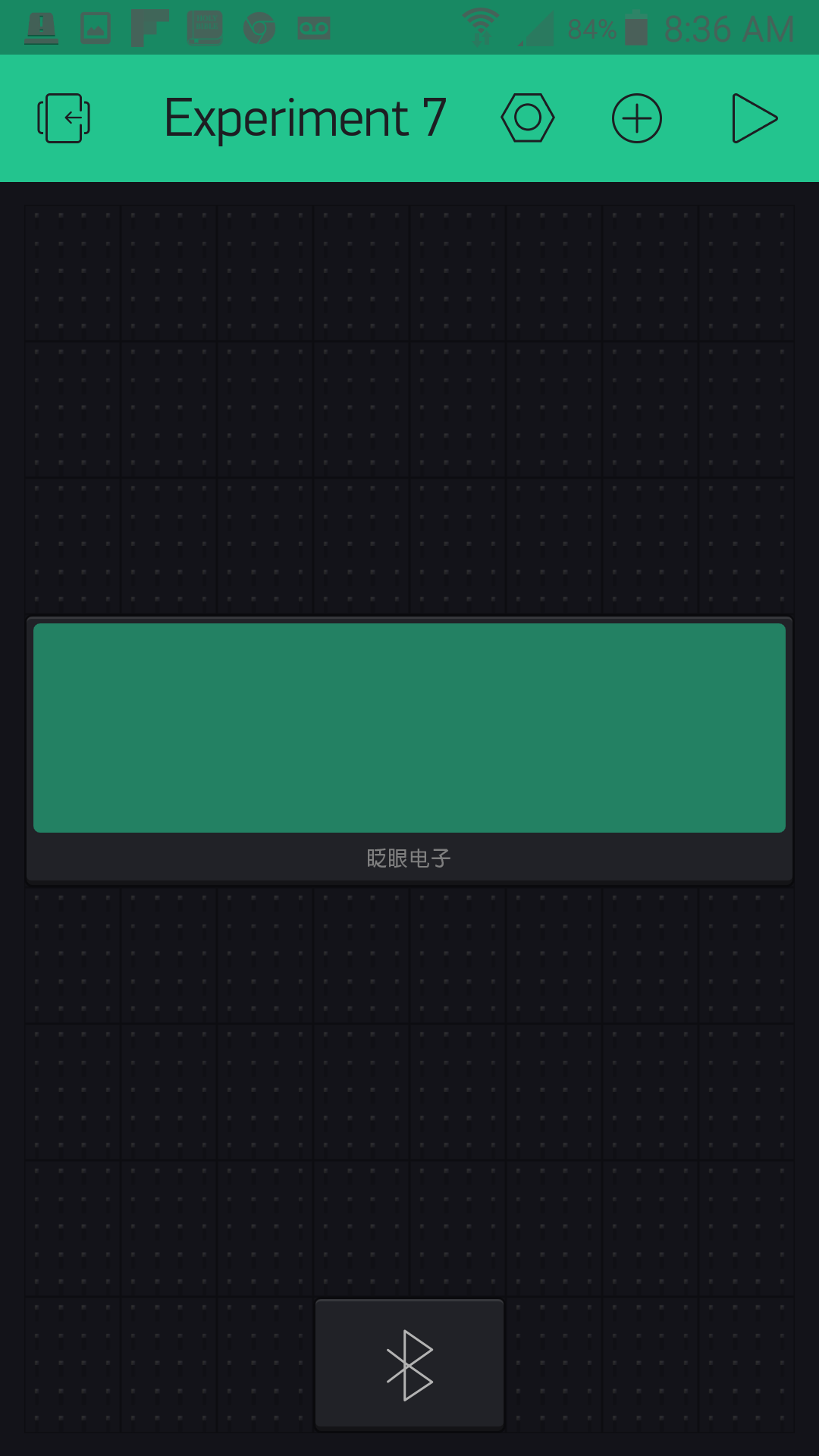
Now open the settings for the LCD widget. You have two pins that you need to assign, and each one has its own row in the LCD. Set the first one to V0 and the second one to V1 as shown. Next set the reading rate; since moisture monitoring is a pretty slow process, a five-second period is fine, and you could probably even go longer. Finally comes the fun part: the message itself!
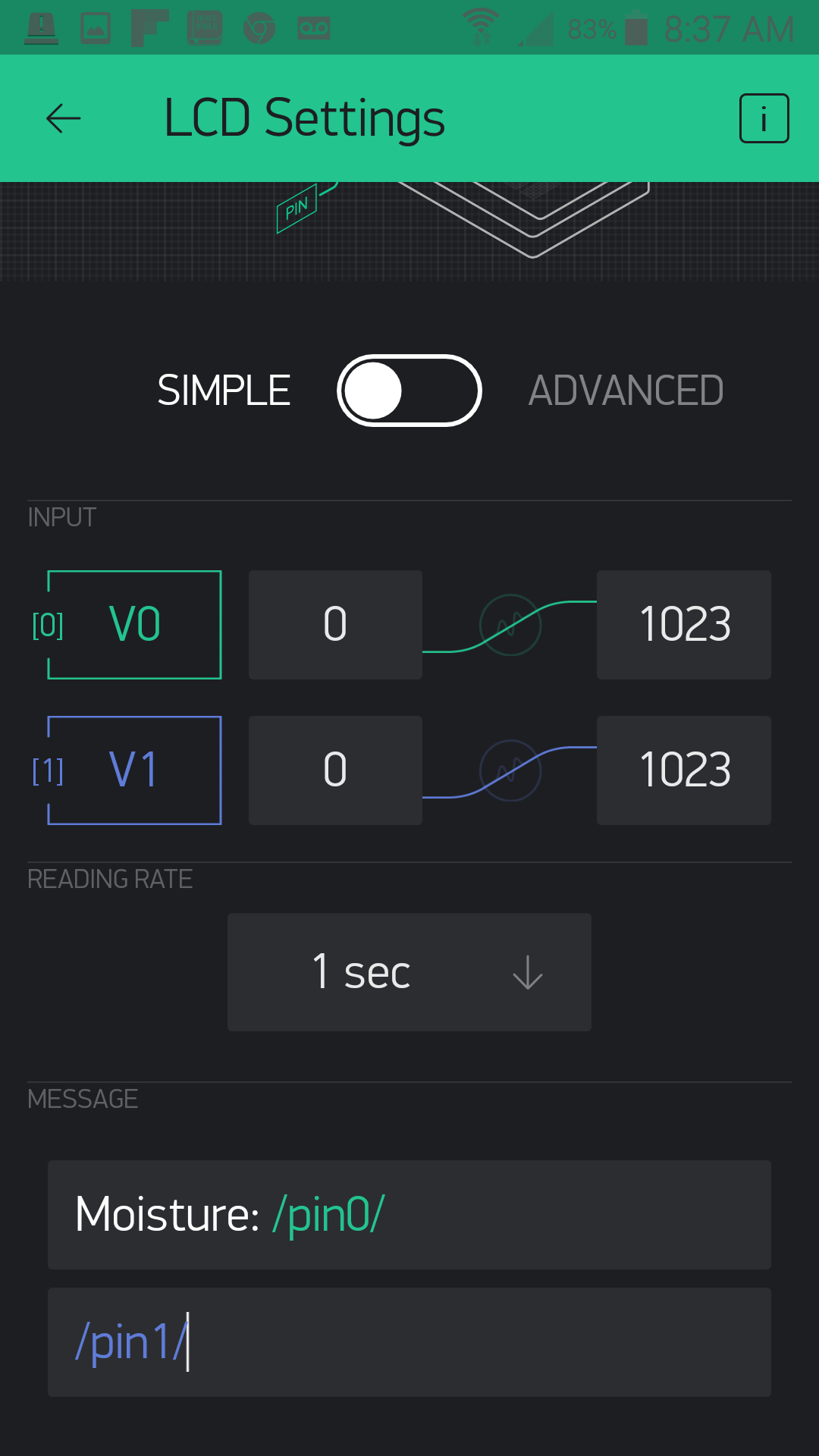
There are two rows to the message. In the first one we are going to display the raw moisture value. You can insert whatever test you want; we added "moisture: " and then /pin0/. Whenever you see /pin0/ or /pin1/ that is a placeholder for the data being sent to pins V0 and V1. Blynk will insert that data in its place. So, the second row will be whatever string of text is sent to pin V1 and will change as the moisture level changes.
That's it! We told you this app would be simple, but powerful in terms of displaying data. Your app should look something similar to this before you upload and run your sketch.
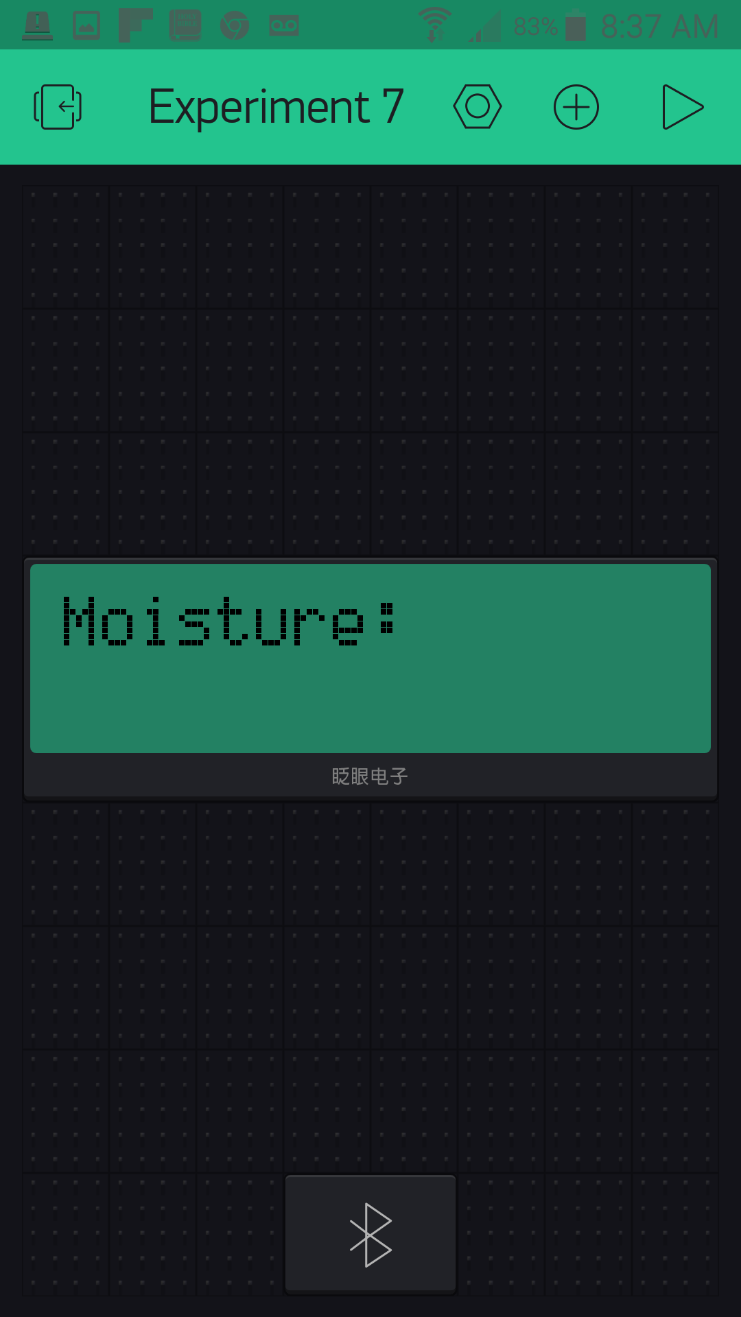
Uploading Your Sketch
Open the Arduino IDE software on your computer. Coding in the Arduino language will control your circuit.
You can type out or copy and paste the following code into the Arduino IDE. Hit upload, and see what happens!
language:cpp
/********************************************************************************
SparkFun Around-The-Home SIK Expansion Kit, Experiment 7
SparkFun Electronics
Product URL

Detect the soil moisture of a potted plant using the Arduino 101 and then display whether you should water it or not through a Blynk app.

This example is written by: Derek Runberg, Educational Technologist

This sketch was written by SparkFun Electronics, with lots of help from the Arduino community.
This code is completely free for any use.

View circuit diagram and instructions at:https://learn.sparkfun.com/tutorials/around-the-home-expansion-kit

********************************************************************************/

//#define BLYNK_USE_DIRECT_CONNECT

/* Comment this out to disable prints and save space */
#define BLYNK_PRINT Serial


#include <BlynkSimpleCurieBLE.h>
#include <CurieBLE.h>

// You should get Auth Token in the Blynk App.
// Go to the Project Settings (nut icon).
char auth[] = "YOUR_AUTH_TOKEN";

BLEPeripheral  blePeripheral;

//Moisture preset values
int dry = 100;
int damp = 600;

//sensor pin constant set at A0
const int SENSOR_PIN = A0;

//create a BlynkTimer object called timer
BlynkTimer timer;

void setup()
{
  // Debug console
  Serial.begin(9600);

  delay(1000);

  blePeripheral.setLocalName("Exp_07");
  blePeripheral.setDeviceName("Exp_07");
  blePeripheral.setAppearance(384);

  Blynk.begin(blePeripheral, auth);

  blePeripheral.begin();

  Serial.println("Waiting for connections...");
  //set interval of 1 second to trigger the sendValues function
 timer.setInterval(500L, sendValues);
}

void loop()
{
  blePeripheral.poll();
  Blynk.run();
}

//custom function called sendValues
void sendValues() {
  //read moisture sensor value


}

BLYNK_READ(V0){
  int moisture = analogRead(A0);
  //write raw value to Blynk on pin V0
  Blynk.virtualWrite(V0, moisture);

  //if moisture is less that or equal to dry...
  if (moisture <= dry) {
    //write the string "I'm parched" to virtual pin 1
    Blynk.virtualWrite(V1, "I'm Parched!");
  }
  //else if moisture is greater than or equal to damp...
  else if (moisture >= damp) {
    //write the string "I'm drowning" to virtual pin 1
    Blynk.virtualWrite(V1, "I'm Drowning!");
  }
  else {
    //write the string "I'm good!" to virtual pin 1
    Blynk.virtualWrite(V1, "I'm Good!");
  }
}
Code to Note
If Arduino is not new to you, then you are well aware of the delay() command. It is how you slow down your sketch or deal within timing of things. But, as you may have noticed in previous sketches, sometimes using a delay() will cause latency, or the piling up of delay commands that add up to your sketch acting sluggish and not doing what you expect. Working with Blynk is really sensitive to this! The way this problem is solved is by using event functions within the Blynk library!
BLYNK_READ(V0){....}
Certain Blynk widgets have timed intervals at which they read or poll specific pins, either physical or virtual. There is an event function called BLYNK_READ(), which is triggered every time one of these widgets reads that pin. In this case, the LCD widget reads pin V0 once every five seconds. You can set this interval with the widget settings in your app. In this use case of a moisture sensor and a potted plant, you would probably want a longer interval, but we shortened it to make it more responsive for a better demonstration.
language:cpp
int moisture = analogRead(A0);
//write raw value to Blynk on pin V0
Blynk.virtualWrite(V0, moisture);
Within the BLYNK_READ() event function we read the moisture sensor on pin A0 and store it in a local variable called moisture. We then write this value to virtual pin V0 every time the Blynk app calls a read over pin V0. In this case, as stated before, every five seconds.
language:cpp
  //if moisture is less that or equal to dry...
  if (moisture <= dry) {
    //write the string "I'm parched" to virtual pin 1
    Blynk.virtualWrite(V1, "I'm Parched!");
  }
  //else if moisture is greater than or equal to damp...
  else if (moisture >= damp) {
    //write the string "I'm drowning" to virtual pin 1
    Blynk.virtualWrite(V1, "I'm Drowning!");
  }
  else {
    //write the string "I'm good!" to virtual pin 1
    Blynk.virtualWrite(V1, "I'm Good!");
  }
}
We use a series of if() statements to write different strings depending on the moisture level, from "I'm Parched" to "I'm Drowning" --- all using the Blynk.virtualWrite() method, but this time to pin V1. The great thing about virtual pins is that they are more buckets than pins. They can store pretty much any data you want to write to them. In this case, whole strings of characters.
What You Should See
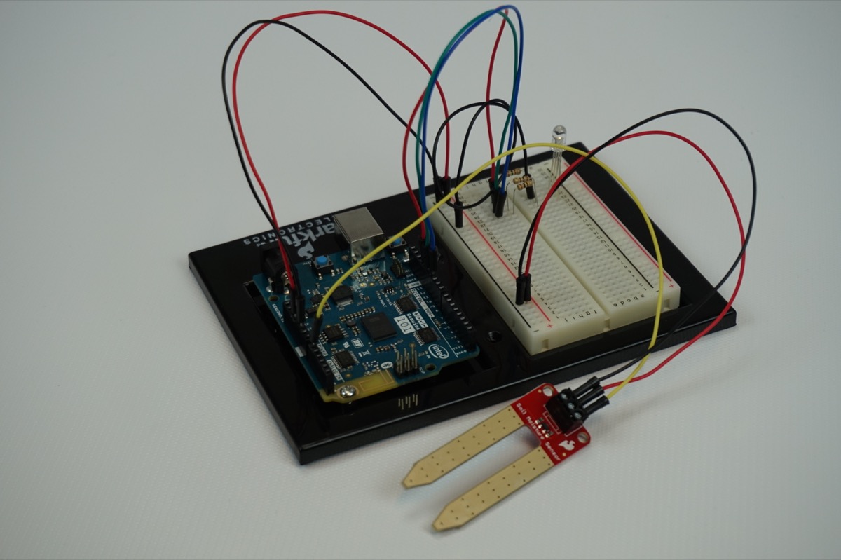
Now, plug your project into the wall using the power supply and insert the moisture sensor into a potted plant, or if you don't have a green thumb, maybe just some soil outside.
Then open your Blynk app and connect to your project via BLE. The LCD screen on your app should display two lines. The first line should say "Moisture: XXX" with XXX being a number value. The second string should be one of the statements we wrote to pin V1..."I'm Parched!" or "I'm Good!" or "I'm Drowning!"
Add water to the soil and see what happens!
[Video]
Troubleshooting
Blynk Shortcut!
If you are having troubles duplicating the functionality above in the Blynk app, scan this QR code with Blynk to get a clone of this experiment!
Experiment 8: Atmospheric Conditions with BME280
Introduction
The sensor used in this experiment is pretty sophisticated. The BME280 reads barometric pressure, temperature and humidity. It can even extrapolate altitude based on pressure changes! It communicates all that data to the Arduino 101 using a serial protocol called I2C (Inter-Integrated Circuit). This sensor has library support for Arduino and works out of the box. In this experiment we will be building an environmental monitoring system with the BME280 and displaying the data in Blynk. With this device you will be able to carry around and monitor the atmospheric conditions in real time. This is great for figuring out heating and cooling issues, checking your altitude, or even just checking the temperature around you if you decide to make it portable in a backpack...or dare I say fanny pack?
Suggested Reading
The following tutorial provides in-depth background on some of the hardware concepts in this experiment:
Parts Needed
You will need the following parts for this experiment:
- 1x Arduino 101 Board (From your Arduino 101 SIK)
- 1x Breadboard (From your Arduino 101 SIK)
- 1x The BME280 Atmospheric Sensor
- 6x Jumper Wires (From your Arduino 101 SIK)
Didn't Get the Around-the-Home Expansion Kit?
If you are conducting this experiment and didn't get the Around-the-Home Expansion Kit, we suggest using these parts:
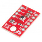
Headers or No Headers?
Note:If you are buying the breakout boards (BME280 Breakout) seperate from this kit you will also need to buy female breakaway pins and assemble (solder) the pins to your board yourself.
Arduino 101
DEV-13787Introduction to the BME280

The SparkFun BME280 Atmospheric Sensor Breakout is an easy way to measure aspects of the atmosphere around you, including pressure, humidity and air temperature. All of this is combined into a petite package called a breakout board.
The 3.3V breakout is power-efficient, using as little as 5µA (that's 1/1,000,000 of an amp!) when idling and less than 1mA when taking measurements. There are 10 pins on the breakout board, but six is the maximum ever used at one time.
In this experiment you will work with the BME280 to read the temperature, pressure and humidity of the room as well as your altitude based off of the atmospheric pressure and print it out on the LCD screen. Finally, in the Touch of Blynk section you will use your BME280 to send atmospheric data to your Blynk app.
Hardware Hookup
Is it hot in here, or is it just me? Let's find out using this sensor, but first you need to hook it up!
Wiring Diagram for the Experiment
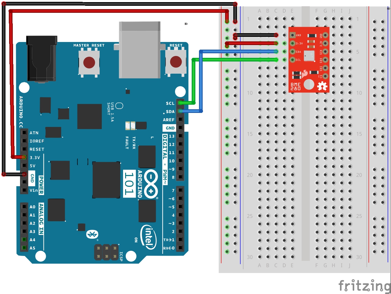
Build Your Blynk App
This Blynk app is going to start looking more and more like a professional-grade app. We will be adding tabs to your app so that you can switch between live line graphs of the temperature, humidity and pressure on the first page and a table of that data on the second tab. You can add tabs to your app using the Tabs widget under the Interface section of the Widget Box menu. In fact, take a bit to check out the other interface options you have at your disposal. You have actually already used one in the Time Input widget. These are really fun and add a certain amount of polish to your app.
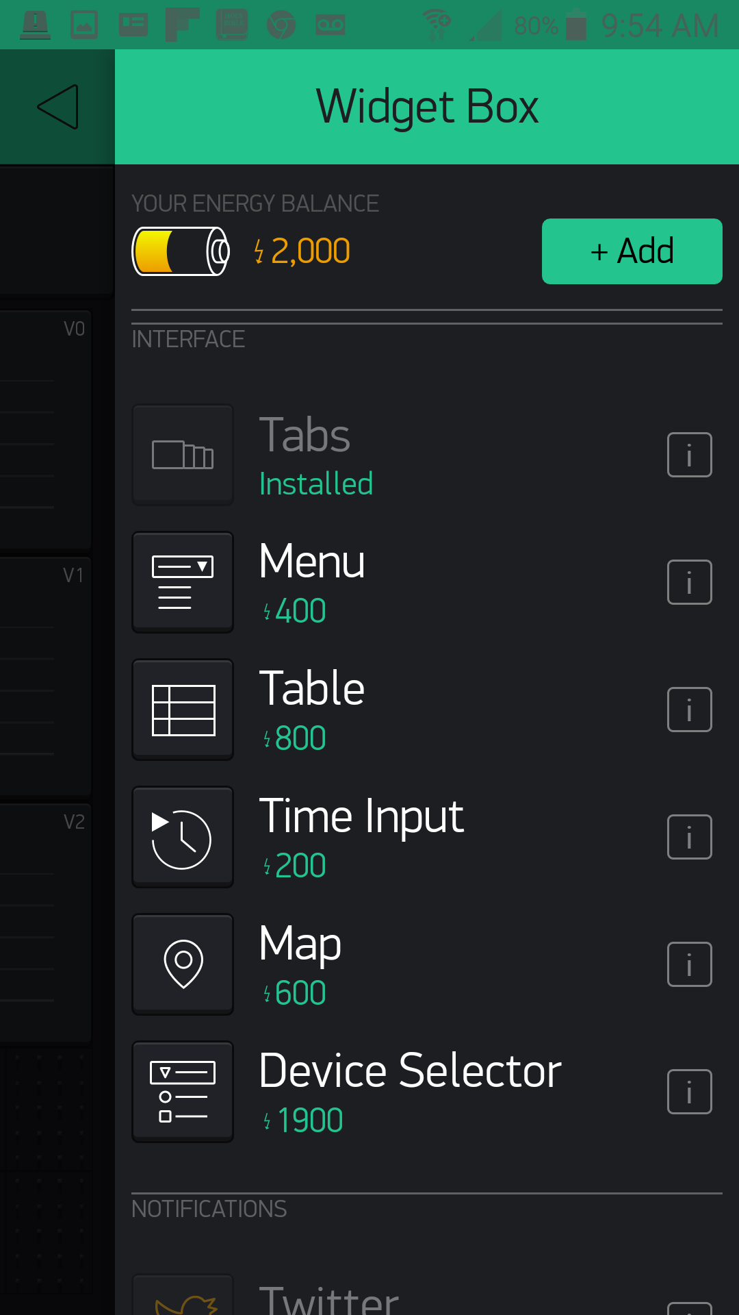
You add your Tabs widget like anything else, but it auto-populates itself at the top. From there you can open the settings like any other widget, name your tabs and even add more. We named our two tabs "Live Data" and "Logged Data."
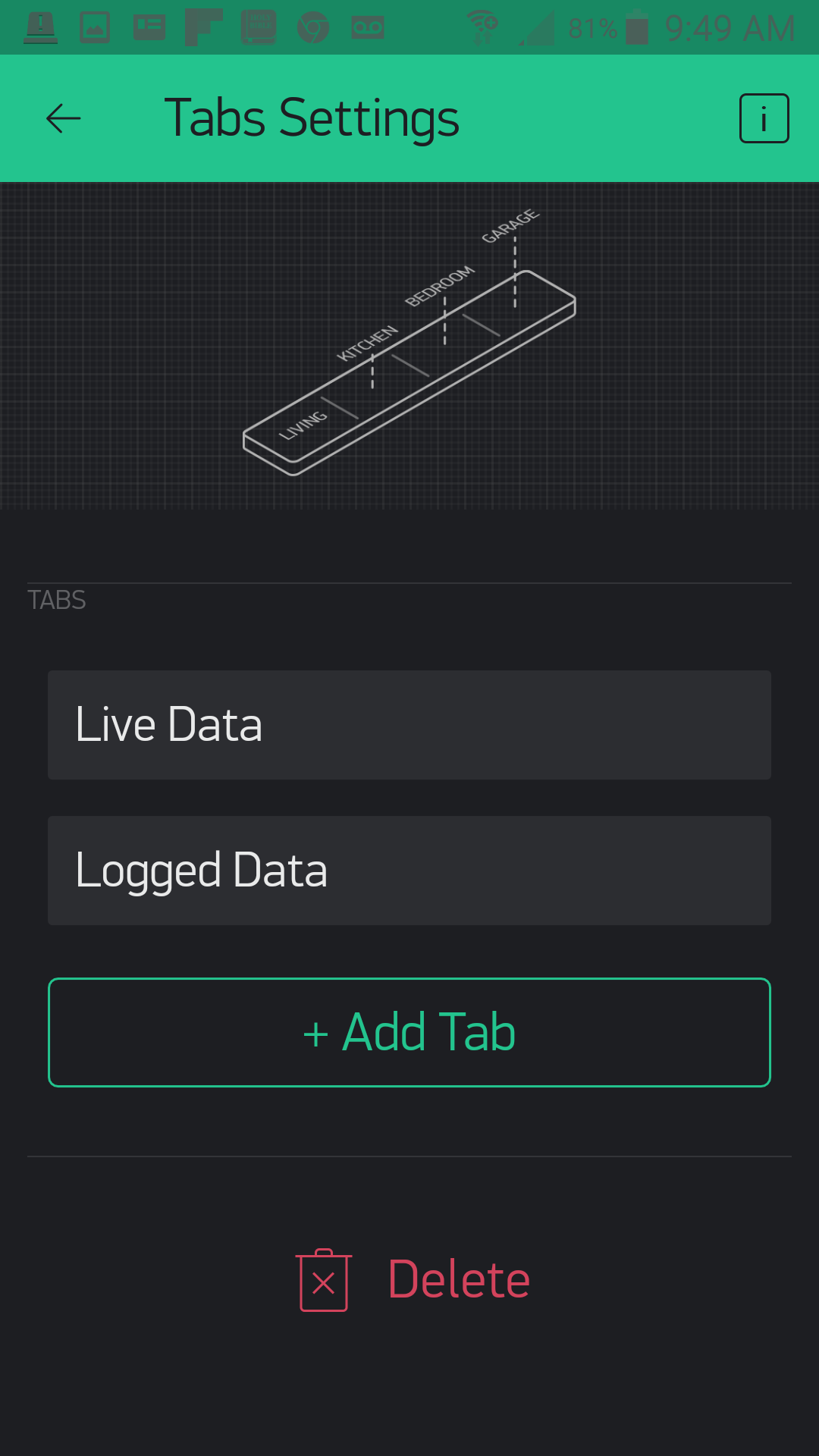
Now, working on the "live data" tab, we add three line graphs --- one for each of the pieces of data that we are graphing: Temperature, Humidity and Pressure. We set all three to line graphs.
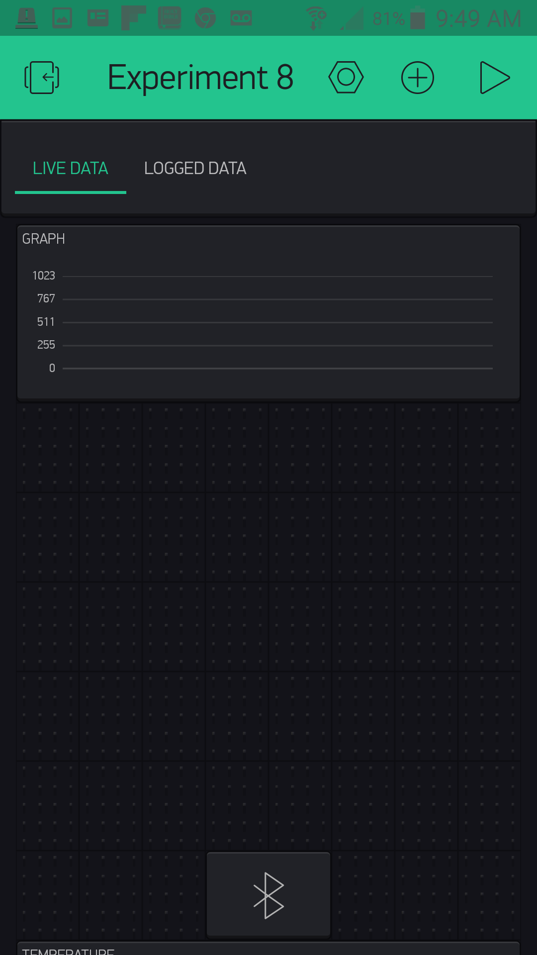
Temperature is set to pin V0, Humidity is pin V1, and Pressure is pin V2. You can also change the line colors to your taste. Also note that we set our expected value range to something that makes sense. Temperature, for example, is a range from 0 to 110, and humidity is 0 to 100.
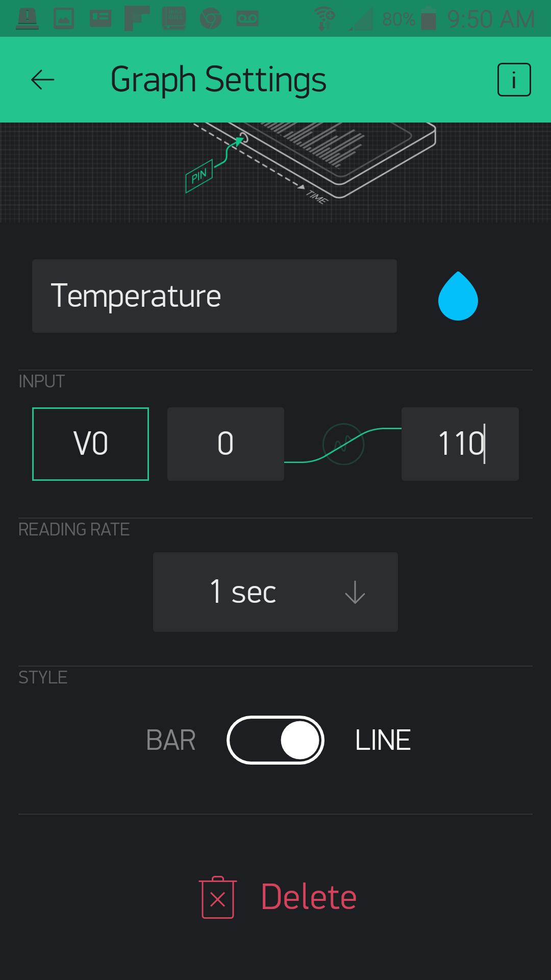
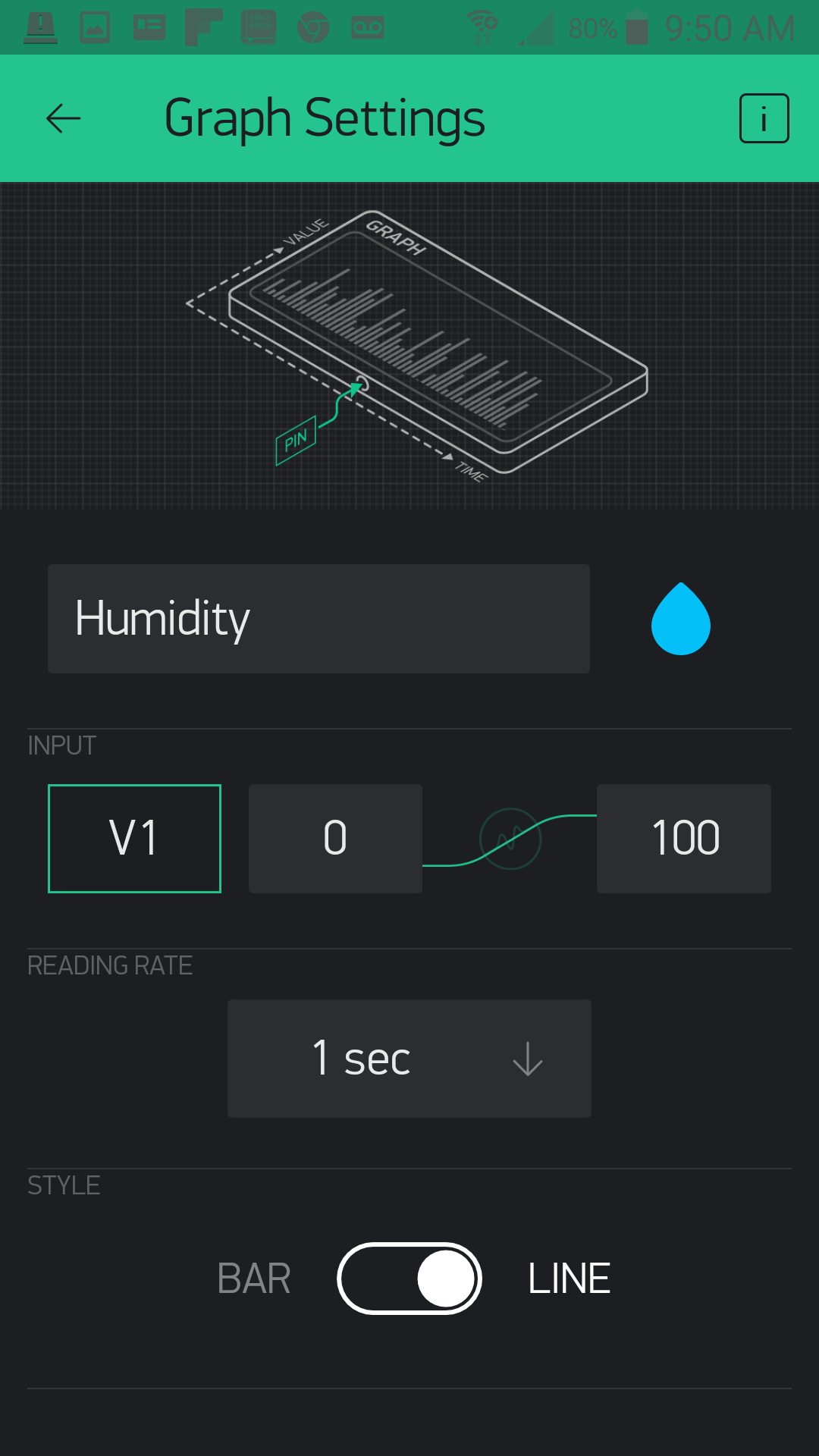

Next, we head over to the "Logged Data" tab and add a Table Widget. We want to connect the table to any data we send it over pin V3 in our Arduino sketch. In terms of the options, we set the columns to "name|value" and do not allow reordering since we will not be time-stamping this table (perhaps that is something you would like to add later).
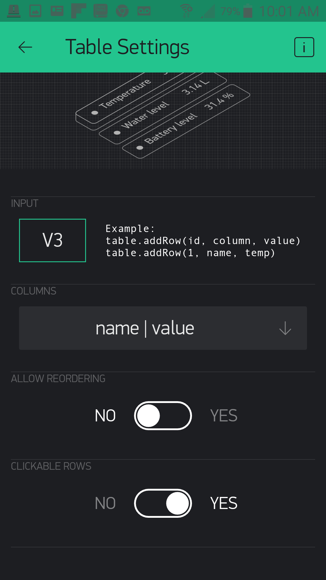
With that we are done with our app setup, and it is now time to get the code uploaded and start sending data to the app so you can use this project to explore the atmospheric data around you!
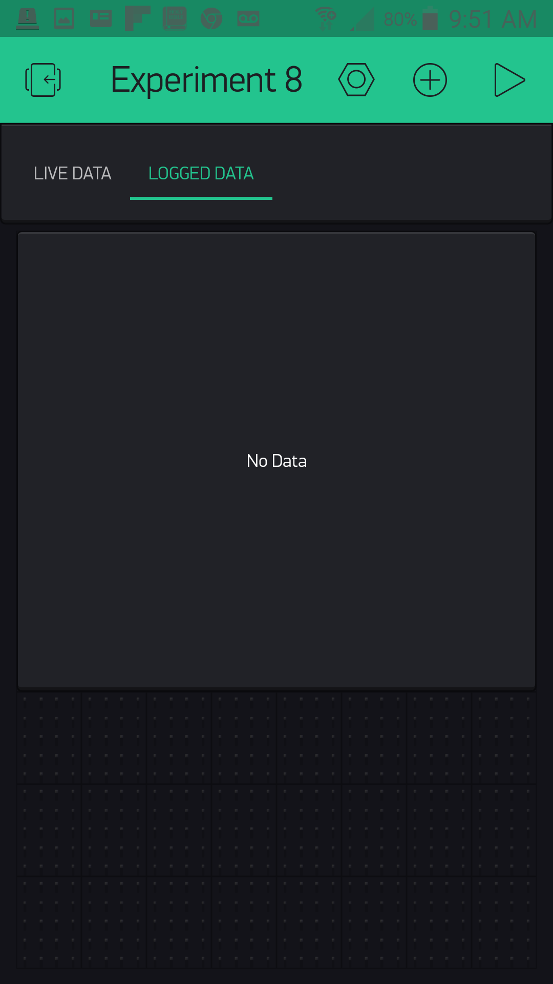
Uploading Your Sketch
Installing the BME280 Arduino Library
You can copy and paste the following code into the Arduino IDE. Hit upload, and see what happens!
language:cpp
/********************************************************************************
SparkFun Around-The-Home SIK Expansion Kit, Experiment 8
SparkFun Electronics
Product URL

Read the Humidity, Temperature and atmospheric pressure of your house and then log and graph it real time in a Blynk app.

This example is written by: Derek Runberg, Educational Technologist

This sketch was written by SparkFun Electronics, with lots of help from the Arduino community.
This code is completely free for any use.

View circuit diagram and instructions at:https://learn.sparkfun.com/tutorials/around-the-home-expansion-kit

********************************************************************************/

//#define BLYNK_USE_DIRECT_CONNECT

/* Comment this out to disable prints and save space */
#define BLYNK_PRINT Serial

#include "SparkFunBME280.h"
#include "Wire.h"
#include <BlynkSimpleCurieBLE.h>
#include <CurieBLE.h>

// You should get Auth Token in the Blynk App.
// Go to the Project Settings (nut icon).
char auth[] = "YOUR_AUTH_TOKEN";

BLEPeripheral  blePeripheral;
BME280 mySensor;
BlynkTimer timer;

int temperature, humidity, pressure;
int rowIndex = 0;

void setup()
{
  //BME280 configuration
  mySensor.settings.commInterface = I2C_MODE;
  mySensor.settings.I2CAddress = 0x77;

  mySensor.settings.runMode = 3; //  3, Normal mode
  mySensor.settings.tStandby = 0; //  0, 0.5ms
  mySensor.settings.filter = 0; //  0, filter off
  //tempOverSample can be:
  //  0, skipped
  //  1 through 5, oversampling *1, *2, *4, *8, *16 respectively
  mySensor.settings.tempOverSample = 1;
  //pressOverSample can be:
  //  0, skipped
  //  1 through 5, oversampling *1, *2, *4, *8, *16 respectively
  mySensor.settings.pressOverSample = 1;
  //humidOverSample can be:
  //  0, skipped
  //  1 through 5, oversampling *1, *2, *4, *8, *16 respectively
  mySensor.settings.humidOverSample = 1;

  //start the sensor
  mySensor.begin();

  // Debug console
  Serial.begin(9600);

  delay(1000);

  blePeripheral.setLocalName("Exp_08");
  blePeripheral.setDeviceName("Exp_08");
  blePeripheral.setAppearance(384);

  Blynk.begin(blePeripheral, auth);

  blePeripheral.begin();

  Serial.println("Waiting for connections...");
  //set interval of 1 second to trigger the sendValues function
  timer.setInterval(100L, sendValues);
 }

void loop()
{
  blePeripheral.poll();
  Blynk.run();
}

//custom function called sendValues
void sendValues() {
  //write temperature and humidity to table

}

BLYNK_READ(V0){
  temperature = mySensor.readTempF();
  Blynk.virtualWrite(V0,temperature);
}

BLYNK_READ(V1){
  humidity = mySensor.readFloatHumidity();
  Blynk.virtualWrite(V1,humidity);
  Blynk.virtualWrite(V3, "add", rowIndex, "humidity%", humidity);
  rowIndex++;
}

BLYNK_READ(V2){
  pressure = mySensor.readFloatPressure() / 100;
  Blynk.virtualWrite(V2,pressure);
}
Code to Note
This sketch is not that complicated in terms of anything new from the Blynk API; it is using the BME280 in Arduino that will be the new kid on the block for the Code to Note.
#include "SparkFunBME280.h"
To simplify the programming in Arduino to use the BME280, we created a library to keep things clean and straightforward for you. You have to include that library in your sketch to be able to use it.
BME280 mySensor;
You then create a BME280 object. We called ours "mySensor," but you can call it whatever you like!
language:cpp
  //BME280 configuration
  mySensor.settings.commInterface = I2C_MODE;
  mySensor.settings.I2CAddress = 0x77;

  mySensor.settings.runMode = 3; //  3, Normal mode
  mySensor.settings.tStandby = 0; //  0, 0.5ms
  mySensor.settings.filter = 0; //  0, filter off
  //tempOverSample can be:
  //  0, skipped
  //  1 through 5, oversampling *1, *2, *4, *8, *16 respectively
  mySensor.settings.tempOverSample = 1;
  //pressOverSample can be:
  //  0, skipped
  //  1 through 5, oversampling *1, *2, *4, *8, *16 respectively
  mySensor.settings.pressOverSample = 1;
  //humidOverSample can be:
  //  0, skipped
  //  1 through 5, oversampling *1, *2, *4, *8, *16 respectively
  mySensor.settings.humidOverSample = 1;
The BME280 is a great sensor because you have a lot of options in terms of how to use it, and it can be configured in a number of different ways. But, it can also be daunting when you first approach using it. If you want to learn more about these settings, we highly recommend reading the Hookup Guide for the BME280; otherwise just leave everything as is.
mySensor.begin();
After all of that we start using the sensor by calling mySensor.begin(). This applies all of the settings changes and starts reading values from the sensor.
language:cpp
BLYNK_READ(V0){
 temperature = mySensor.readTempF();
 Blynk.virtualWrite(V0,temperature);
}
As in the previous experiment, we put the BLYNK_READ() event function to use. This time each graph has its own event function. In our example code they are all set to the same timing, but you could easily change each one to make sense for your application. For example, you could probably get away with not tracking pressure as often as you would temperature or humidity.
language:cpp
 Blynk.virtualWrite(V3, "add", rowIndex, "humidity%", humidity);
 rowIndex++;
You may have noticed that the humidity graph event function (reading on pin V1) has a little extra code in it. This is because we decided to track the humidity percentage in a table on the "Logged Data" tab. To add data to a table you use the virtualWrite() method, but add a few extra parameters. You add the pin that is connected to the table --- in this case V3 --- the command to "add" to the table, the row you want to add data to, the title of the row and finally the data. We are adding a new row in a running manner by incrementing a variable called rowIndex.
What You Should See
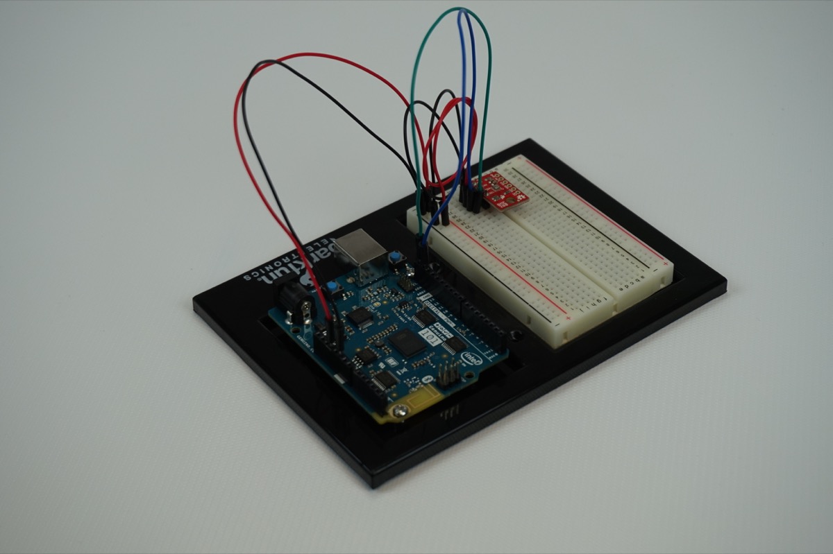
[Video]
As a bonus to this experiment, we added a Map Widget just below the table to give our location, which is based off of our phone. Check it out!
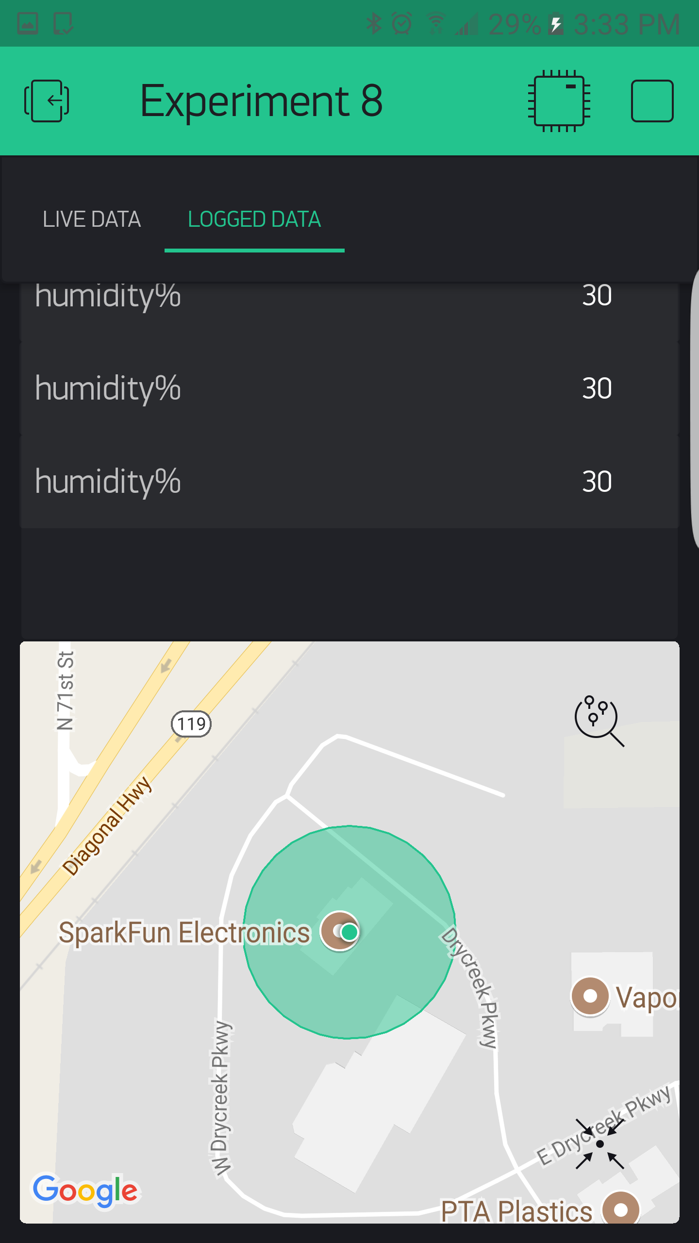
Troubleshooting
Blynk Shortcut!
If you are having troubles duplicating the functionality above in the Blynk app, scan this QR code with Blynk to get a clone of this experiment!
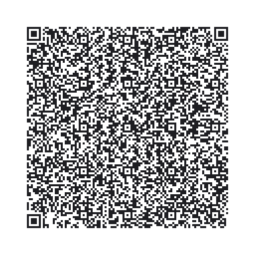
Experiment 9: Using a Current Sensor
Introduction
In Experiment 1 you gained ultimate control over being able to turn on and off appliances that plug into the wall through the use of the IoT Relay. But you didn't have a way to determine if the appliance was on, off or even plugged in, let alone the ability to track how much current it was using. Well, that is all going to change with this experiment!
In this experiment you are going to learn about the Non-Invasive Current Sensor (NICS). The NICS clips around a single wire of an extension cord that is plugged into the power cord of any appliance and, with some basic wiring, will enable you to track the amount of current a given appliance is consuming at that moment without having to mess with exposed AC high-voltage wiring. You will be building a device that you can plug a device or appliance into to measure the number of watts that it uses. This is great for figuring out what appliances are using how much power, and later this circuit is a great way to detect if a device is on or off by way of monitoring how many watts it pulls.
Parts Needed
You will need the following parts:
- 1x Breadboard (From your Arduino 101 SIK)
- 1x Arduino 101 Board (From your Arduino 101 SIK)
- 1x TRRS Connector Breakout
- 1x Passive Current Sensor
- 1x 10 uF Capacitor
- 2x 10k Ohm Resistor (From your Arduino 101 SIK)
- 1x 100 Ohm Resistor (From your Arduino 101 SIK)
- 7x Jumper Wires (From your Arduino 101 SIK)
- 1x Air Conditioner Extension Cord, 3' (Amazon)
Didn't Get the Around-the-Home Expansion Kit?
If you are conducting this experiment and didn't get the Around-the-Home Expansion Kit, we suggest using these parts:

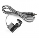
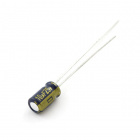
Headers or No Headers?
Note:If you are buying the breakout boards (TRRS Breakout) seperate from this kit you will also need to buy female breakaway pins and assemble (solder) the pins to your board yourself.
Arduino 101
DEV-13787Suggested Reading
Before continuing with this experiment, we recommend you be familiar with the concepts in the following tutorials:
- Light-Emitting Diodes --- Learn more about LEDs
- Switch Basics --- Learn more about buttons and switches
Introducing the Current Sensor

The Non-Invasive Current Sensor (NICS) has a "jaw" that clamps around a wire. It can read the amount of current flowing through the wire without the wire itself having to be modified (ergo, non-invasive). By an appliance into an extension cord and then using the current sensor to detect how much current is going through the extension cord, we'll be able to tell when the AC is running.
The current sensor's output is a current much lower than, but linearly related to, the current it's sensing.
TRRS Breakout
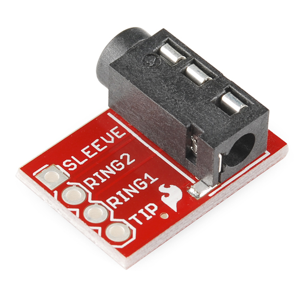
The NICS has a connector that looks like an audio jack on one end. It is a TRS (Tip-Ring-Sleeve) connector, shown on the left side of the diagram below. You may also have seen TRRS connectors (Tip-Ring-Ring-Sleeve, right side of diagram), which are commonly used for hands-free headsets. The TRRS breakout makes each of the pieces of a TRRS connector (the tip, each of the two rings and the sleeve) accessible. The TRRS breakout will allow us to easily connect to the tip and the sleeve of the current sensor's connector so we can read its values.
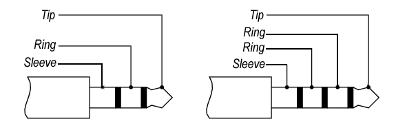
OK, now that we have figured out the new parts at the party, let's build the circuit!
Hardware Hookup
Ready to start hooking everything up? Check out the wiring diagram below to see how everything is connected.
Wiring Diagram for the Experiment
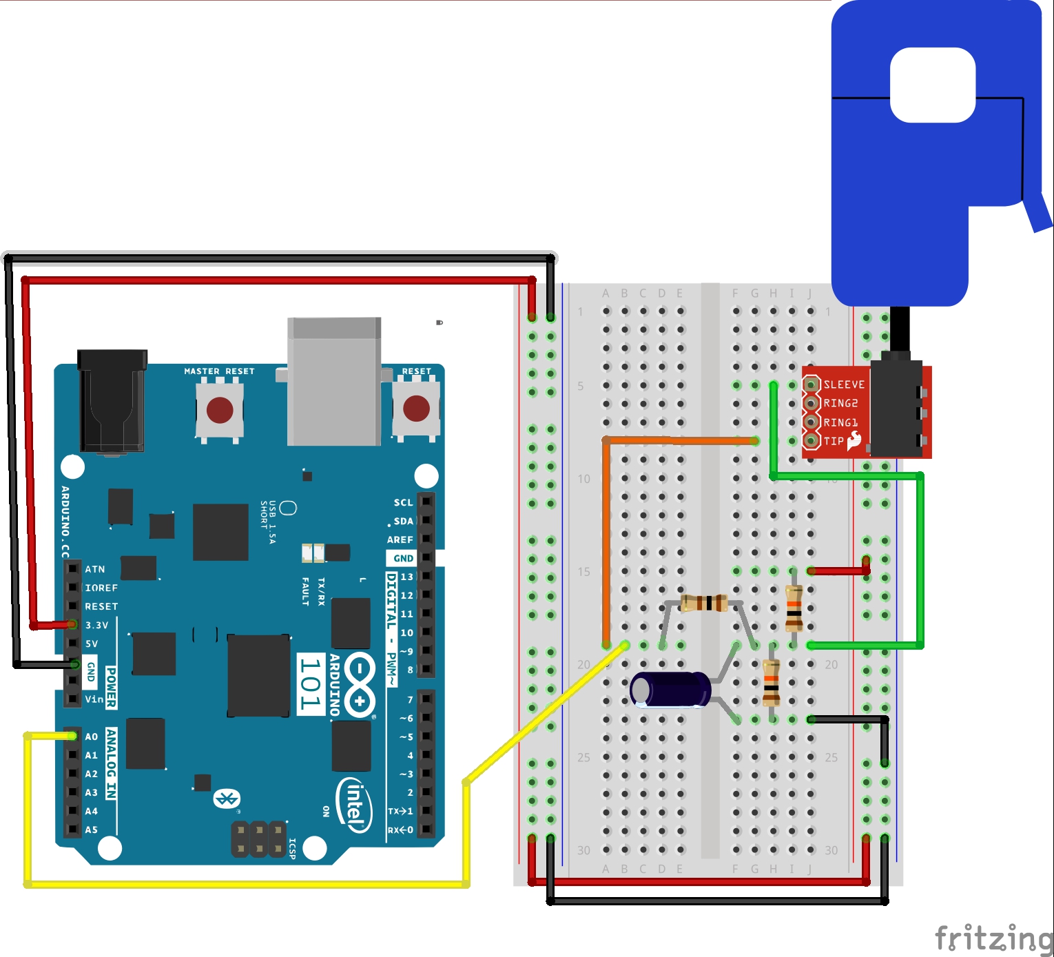
To hook the current sensor up to the extension cord you'll need a sharp utility knife and a safe, clean cutting surface. On your surface, lay the Air Conditioner Extension Cord flat, and use the utility knife to separate one of the three joined sections of wire. Make the cut approximately 3 to 4 inches long—just long enough to put the current sensor's top "jaw" through and safely clip it together.
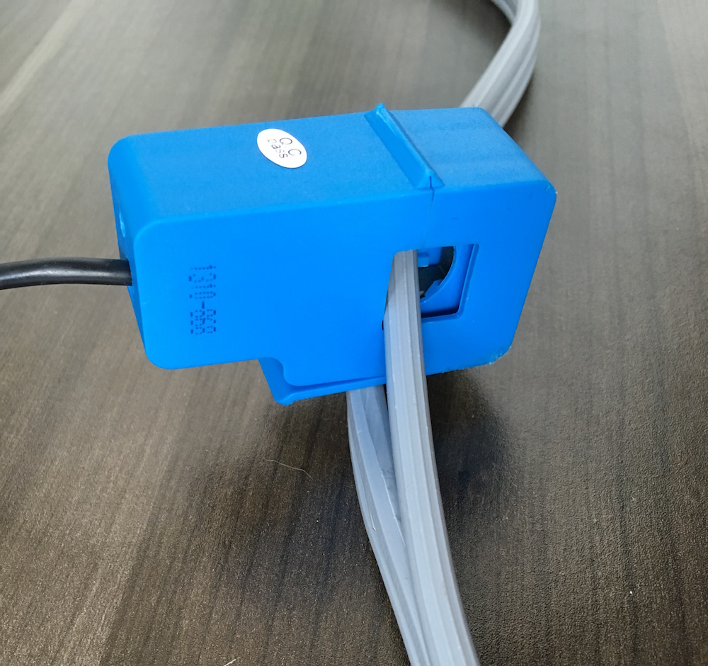
Build Your Blynk App
In creating this app you will build a gauge that will display the wattage of the device you are measuring in real time, as well as a graph of the time that your phone is connected to it. So, you can see where you are and where you have been (short term) --- and watch the wattage use over the time that you are watching.
As with all of the Blynk apps that use the Arduino 101 board, add the BLE widget and open the settings to connect your phone to the Arduino 101. Once you have added the BLE widget, you can start to add the other widgets for this app. We start out by bringing the gauge widget into your app and opening the widget settings. This gauge will display the wattage draw from the NICS, which we will be writing to pin V0.
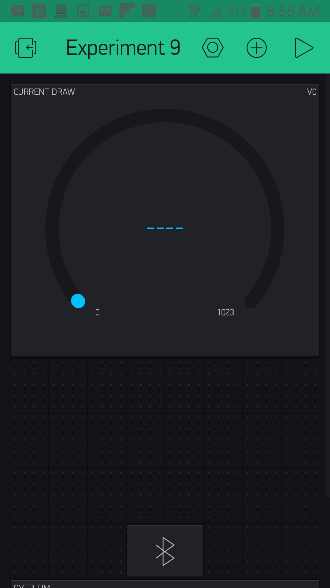
Open the settings of your gauge. Name your gauge (we labeled ours "Wattage") and set the pin to pin V0. For this we also changed the value range to 0--20, as we probably wouldn't be pulling 1023 amps from an appliance. The last setting is the Label for the gauge, which we set as "Wattage: /pin/ Watts". We placed the gauge and resized it so that it is the dominant view of the app. With that we are done with the gauge.
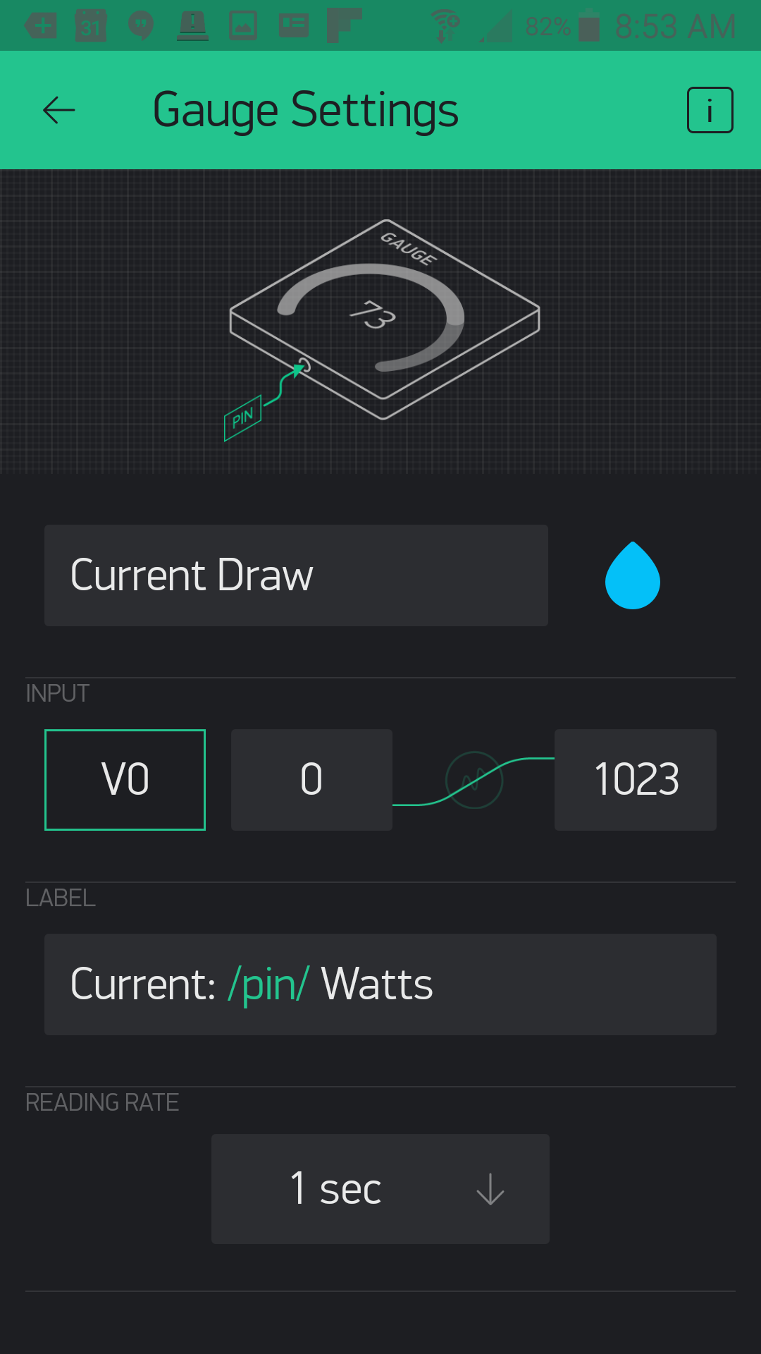
After adding the gauge, you can now add the graph widget and place it below the gauge as shown below.
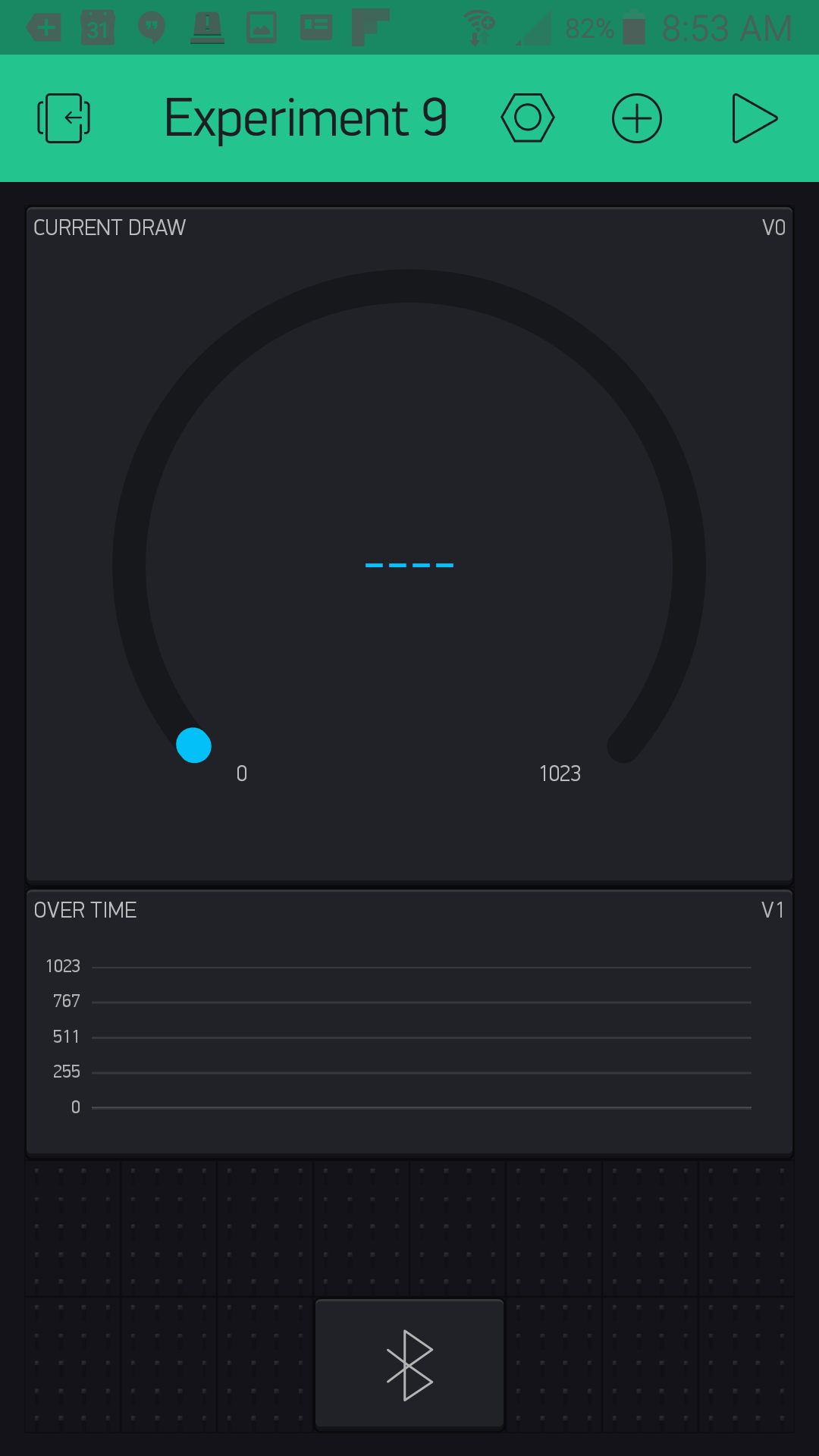
Now, open the graph widget settings. We named our graph "Over Time" as it will display the Wattage use over the time that you have the app opened. We set the pin to pin V1 as we cannot point two widgets at the same virtual pin at the same time; we will fix this in our sketch! In terms of the value range we changed the standard 0--1023 to 0--4000 since these values will be in watts and not a 10-bit (0--1023) number. After doing some extensive research (Google) we found that a dishwasher can consume around 3600 watts, so we aimed for a little higher than that. Finally, we changed the style to Line. With that we are done with the app!

Uploading Your Sketch
Open the Arduino IDE software on your computer. Coding in the Arduino language will control your circuit.
You can type out or copy and paste the following code into the Arduino IDE. Hit upload, and see what happens!
language:cpp
/********************************************************************************
SparkFun Around-The-Home SIK Expansion Kit, Experiment 9
SparkFun Electronics
Product URL

Build a device to measure the power useage of an applicance around your home and then display it in a Blynk app.

This example is written by: Derek Runberg, Educational Technologist

This sketch was written by SparkFun Electronics, with lots of help from the Arduino community.
This code is completely free for any use.

View circuit diagram and instructions at:https://learn.sparkfun.com/tutorials/around-the-home-expansion-kit

********************************************************************************/

/* Comment this out to disable prints and save space */
#define BLYNK_PRINT Serial
#include <BlynkSimpleCurieBLE.h>
#include <CurieBLE.h>
#include <math.h>

BLEPeripheral  blePeripheral;


// You should get Auth Token in the Blynk App.
// Go to the Project Settings (nut icon).
char auth[] = "YOUR_AUTH_TOKEN";


const int CURRENT_SENSOR_PIN = A1;
const int LED_PIN = 13;

int  currentWatts;
int calibratedWattage;

void setup()
{
  blePeripheral.setLocalName("Exp_09");
  blePeripheral.setDeviceName("Exp_09");
  blePeripheral.setAppearance(384);

  Blynk.begin(blePeripheral, auth);
  blePeripheral.begin();

  Serial.begin(9600);

// Setup notification button on pin 2  pinMode(REPLAY_PIN, OUTPUT);
  calibratedWattage = getWatts(CURRENT_SENSOR_PIN);
}

void loop()
{
  currentWatts = getWatts(CURRENT_SENSOR_PIN);
  Serial.println(currentWatts);

  if(currentWatts > calibratedWattage){
    digitalWrite(LED_PIN, HIGH);
  }
  else{
    digitalWrite(LED_PIN, LOW);
  }
  blePeripheral.poll();
  Blynk.run();
}

float getWatts(int pin) {

  // RMS voltage
  const double vRMS = 120.0;      // Assumed or measured

  // Parameters for measuring RMS current
  const double offset = 1.65;     // Half the ADC max voltage
  const int numTurns = 2000;      // 1:2000 transformer turns
  const int rBurden = 100;        // Burden resistor value
  const int numSamples = 1000;    // Number of samples before calculating RMS

  int sample;
  double voltage;
  double iPrimary;
  double acc = 0;
  double iRMS;
  double apparentPower;

  // Take a number of samples and calculate RMS current
  for ( int i = 0; i < numSamples; i++ ) {

  // Read ADC, convert to voltage, remove offset
  sample = analogRead(pin);
  voltage = (sample * 3.3) / 1023;
  voltage = voltage - offset;

  // Calculate the sensed current
  iPrimary = (voltage / rBurden) * numTurns;

  // Square current and add to accumulator
  acc += pow(iPrimary, 2);
  }

  // Calculate RMS from accumulated values
  iRMS = sqrt(acc / numSamples);

  // Calculate apparent power and return it
  apparentPower = vRMS * iRMS;
  return apparentPower;
}

//write the real time current draw of the fan when read from the app
BLYNK_READ(V0) {
  //read current sensor

  Blynk.virtualWrite(0, currentWatts);
}

BLYNK_READ(V1) {
  Blynk.virtualWrite(1, currentWatts);
}
Code to Note
This sketch is by far the heaviest sketch in terms of programming. The good thing is that most of it is collecting readings and calculating equations. We wrapped all of the complicated math into the getWatts() function to give you the option of taking a closer look at how we did it and changing it for your own situation...or just using it out of the box!
language:cpp
int  currentWatts;
int calibratedWattage;
We started out by creating two global variables: one stores the current watts calculated by the Arduino 101 board later in the sketch, and the other stores a calibration value, which is just a single wattage reading in the setup() --- that way we have a starting point to compare to.
calibratedWattage = getWatts(A0);
To get a calibration value we just call the getWatts(A0) function in setup() and store it in the callibrationWattage variable. This only happens once at power-up, so if you want to recalibrate you can use the RESET button on the Arduino 101 board, or power cycle the board.
language:cpp
// RMS voltage
const double vRMS = 120.0;      // Assumed or measured
const double offset = 1.65;     // Half the ADC max voltage
const int numTurns = 2000;      // 1:2000 transformer turns
const int rBurden = 100;        // Burden resistor value
const int numSamples = 1000;    // Number of samples before calculating RMS
Inside of the getWatts() function there are a number of variables that are used to calculate the wattage output of the function and using the NICS. A couple of them that you will need to manipulate depending on your use are:
const double vRMS = 120.0;--- If you are in Europe or measuring an outlet that is higher voltage, you will need to change this.const double offset = 1.65;--- If you are using a 5-volt board, this value should be 2.5.
language:cpp
// Take a number of samples and calculate RMS current
for ( int i = 0; i < numSamples; i++ ) {
// Read ADC, convert to voltage, remove offset
sample = analogRead(pin);
voltage = (sample * 3.3) / 1023;
voltage = voltage - offset;
// Calculate the sensed current
iPrimary = (voltage / rBurden) * numTurns;
// Square current and add to accumulator
acc += pow(iPrimary, 2);
}
// Calculate RMS from accumulated values
  iRMS = sqrt(acc / numSamples);
// Calculate apparent power and return it
apparentPower = vRMS * iRMS;
return apparentPower;
Here are the full calculations from taking the 10-bit analog value from reading pin A0 to calculating the voltage and so on. The comments in the code lead you through the full process. The main thing to note here is that when all is said and done, the function returns a float value using return apparentPower;
currentWatts = getWatts(A0);
In the loop we update the currentWatts variable using the getWatts() function.
language:cpp
BLYNK_READ(V0) {
  Blynk.virtualWrite(0, currentWatts);
}

BLYNK_READ(V1) {
  Blynk.virtualWrite(1, currentWatts);
}
Finally, we respond to the BYLNK_READ() event functions with the same response with a single change of what pin we write to since we cannot point both widgets at the single event...bummer!
Troubleshooting
Blynk Shortcut!
If you are having troubles duplicating the functionality above in the Blynk app, scan this QR code with Blynk to get a clone of this experiment!
Odd Numbers?
Make sure that you have hooked up the circuit correctly, especially the capacitors! Capacitors are highly polarized.
Still odd!
make sure the connection of the RTTS connector is fully inside of the breakout connector and that the sensor itself is correctly fastened around the wire to be read.