SIK Experiment Guide for the Arduino 101/Genuino 101 Board
 D___Run___
 Experiment 7: Reading a Photoresistor
Introduction
In Experiment 2, you got to use a potentiometer, which varies resistance based on the twisting of a knob and, in turn, changes the voltage being read by the analog input pin. In this circuit you’ll be using a photoresistor, which changes resistance based on how much light the sensor receives. You will read the light value of the room and have an LED turn on if it is dark and turn off if it is bright. That's right; you are going to build a night light!
Parts Needed
You will need the following parts:
- 1x Breadboard
- 1x Arduino 101 or Genuino 101 board
- 1x LED
- 1x 100Ω Resistor
- 7x Jumper Wires
- 1x Photoresistor
- 1x 10K Resistor
Didn't Get the SIK?
If you are conducting this experiment and didn't get the SIK, we suggest using these parts:


You will also need either an Arduino 101 OR Genuino 101 board.

Arduino 101
DEV-13787
Genuino 101
DEV-13984Introducing the Photoresistor
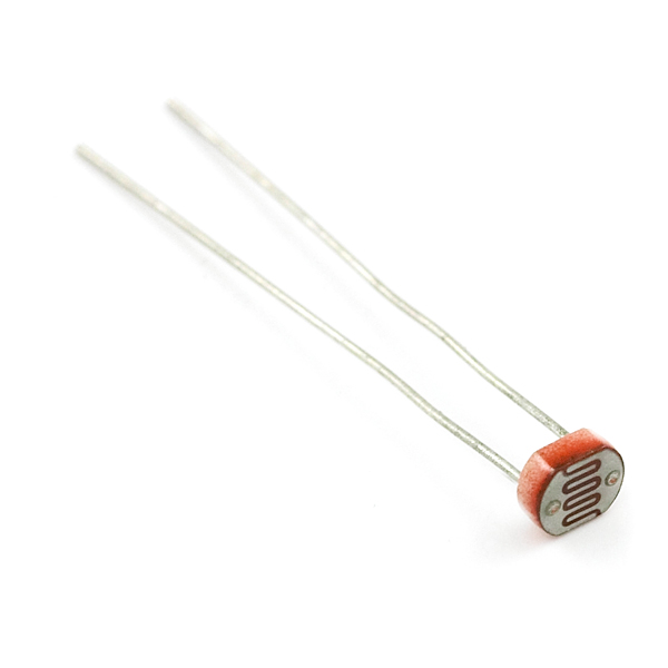
The photoresistor changes its resistance based on the light to which it is exposed. To use this with the 101 board, you will need to build a voltage divider with a 10K Ohm resistor as shown in the wiring diagram for this experiment. The 101 board cannot read a change in resistance, only a change in voltage. A voltage divider allows you to translate a change in resistance to a corresponding voltage value.
The voltage divider enables the use of resistance-based sensors like the photoresistor in a voltage-based system. As you explore different sensors, you will find more resistance-based sensors that only have two pins like the photoresistor. To use them with your 101 board you will need to build a voltage divider like the one in this experiment. To learn more about resistors in general, check out our tutorial on resistors and also our tutorial on voltage dividers.
Note: Make sure you are using the 10K Ohm resistor in your voltage divider with the sensors in this kit. Otherwise you will get odd and inconsistent results.
Hardware Hookup
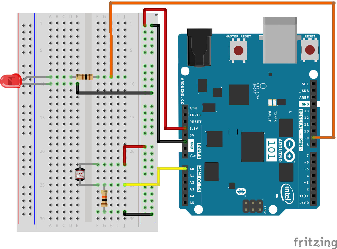
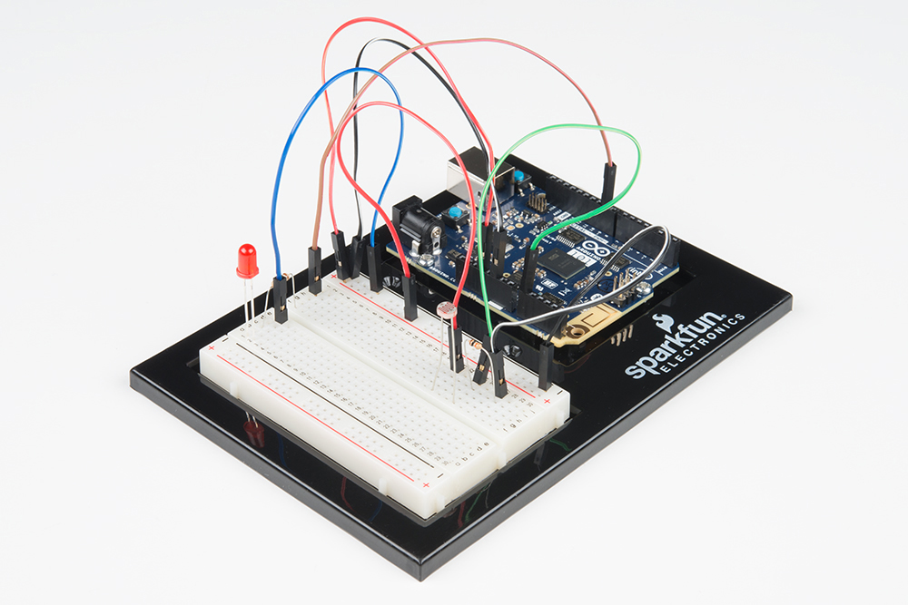
Ready to start hooking everything up? Check out the wiring diagram below to see how everything is connected.
| Polarized Components | Pay special attention to the component’s markings indicating how to place it on the breadboard. Polarized components can only be connected to a circuit in one direction. |
Wiring Diagram for the Experiment
Open the Sketch
Open the Arduino IDE software on your computer. Coding in the Arduino language will control your circuit. Open the code for Circuit 7 by accessing the “101 SIK Guide Code” you downloaded and placed into your “Examples” folder earlier.
To open the code go to: File > Examples > 101 SIK Guide Code > Circuit_07
You can also copy and paste the following code into the Arduino IDE. Hit upload, and see what happens!
language:cpp
/*
SparkFun Inventor's Kit
Example sketch 07

PHOTORESISTOR

  Read a photoresistor (light sensor) to detect "darkness" and turn on an LED when it is "dark" and turn back off again when it is "bright."

This sketch was written by SparkFun Electronics,
with lots of help from the Arduino community.
This code is completely free for any use.
Visit http://learn.sparkfun.com/products/2 for SIK information.
Visit http://www.arduino.cc to learn more about Arduino.
*/


// As usual, we'll create constants to name the pins we're using.
// This will make it easier to follow the code below.

const int sensorPin = 0;
const int ledPin = 9;

// We'll also set up some global variables for the light level a calibration value and     //and a raw light value
int lightCal;
int lightVal;


void setup()
{
  // We'll set up the LED pin to be an output.
  pinMode(ledPin, OUTPUT);
  lightCal = analogRead(sensorPin);
  //we will take a single reading from the light sensor and store it in the lightCal        //variable. This will give us a prelinary value to compare against in the loop
}


void loop()
{
  //Take a reading using analogRead() on sensor pin and store it in lightVal
  lightVal = analogRead(sensorPin);


  //if lightVal is less than our initial reading (lightCal) minus 50 it is dark and         //turn pin 9 HIGH. The (-50) part of the statement sets the sensitivity. The smaller       //the number the more sensitive the circuit will be to variances in light.
  if(lightVal < lightCal - 50)
  {
    digitalWrite(9,HIGH);
  }

  //else, it is bright, turn pin 9 LOW
  else
  {
    digitalWrite(9,LOW);
  }

}
Code to Note
lightCal = analogRead(sensorPin); lightCal is a calibration variable. Your 101 board takes a single reading of the light sensor in the setup and uses this value to compare against the lightVal in the loop. This value doesn't change in the loop, as it is set in the setup function. To update this value you can press the RESET button or power cycle the board.
if(lightVal < lightCal -50) If the light value variable that is constantly being updated in the loop is less than the calibration value set in the setup minus 50, it is dark and the LED should turn on. The (-50) portion of this statement is a sensitivity value. The higher the value, the less sensitive the circuit will be; the lower the value, the more sensitive it will be to lighting conditions.
What You Should See
You should see the LED turn on when it is darker and turn off when it is brighter. Try putting your hand over the sensor and then removing it. If it isn't working, make sure you have assembled the circuit correctly and verified and uploaded the code to your board, or see the Troubleshooting section.
Troubleshooting
LED Remains Dark
You may have been casting a shadow over the sensor when you uploaded your code. Make sure the sensor is exposed to the ambient light of the room and press the MASTER RESET button or re-upload your code. This will reset the calibration value in the setup.
Still Not Quite Working
You may have your logical statement wrong. Double check your code and try adjusting the sensitivity level a little lower or higher. Make sure there is no semicolon after the if() statement. This is a common error and a tricky one to find!