SIK Experiment Guide for the Arduino 101/Genuino 101 Board
 D___Run___
 Experiment 8: Color Mixing with the RGB
Introduction
In this circuit you’ll work with multiple potentiometers. You used a single potentiometer in Experiment 1. Now we are going to dial it up a few notches and use three of them! Why three of them? You are going to use each potentiometer to control the brightness of the three colors (Red, Green and Blue) of an RGB LED to make some more interesting colors than the basic ones you used in Experiment 3.
Get your paint brush out and be ready to paint the rainbow!
You will need the following parts:
- 1x Breadboard
- 1x Arduino 101 or Genuino 101 board
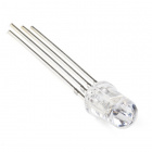
- 1x Common Cathode RGB LED
- 3x 100Ω Resistor
- 15x Jumper Wires
- 3x Potentiometer
Didn't Get the SIK?
If you are conducting this experiment and didn't get the SIK, we suggest using these parts:


You will also need either an Arduino 101 OR Genuino 101 board.

Arduino 101
DEV-13787
Genuino 101
DEV-13984Suggested Reading
Before continuing with this experiment, we recommend you be familiar with the concepts in the following tutorials:
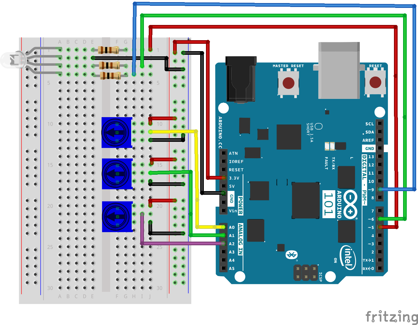
Hardware Hookup
Ready to start hooking everything up? Check out the wiring diagram and hookup table below to see how everything is connected.
| Polarized Components | Pay special attention to the component’s markings indicating how to place it on the breadboard. Polarized components can only be connected to a circuit in one direction. Polarized components are highlighted with a yellow warning triangle, in the table. |
Wiring Diagram for the Experiment
Open the Sketch
Open the Arduino IDE software on your computer. Coding in the Arduino language will control your circuit. Open the code for Circuit 8 by accessing the “SIK Guide Code” you downloaded and placed into your “Examples” folder earlier.
To open the code go to: File > Examples > SIK Guide Code > Circuit_08
**Copy and paste the following code into the Arduino IDE. Hit upload, and see what happens! **
language:cpp
/* SparkFun Inventor's Kit
Example sketch 08

POTENTIOMETER

  Measure the position of each potentiometer and map it to
  the red, green and blue values! Then write those values to the RGB LED.


This sketch was written by SparkFun Electronics,
with lots of help from the Arduino community.
This code is completely free for any use.
Visit http://learn.sparkfun.com/products/2 for SIK information.
Visit http://www.arduino.cc to learn more about Arduino.
*/

//create constants for the three analog input pins
const int redPot = 0;
const int greenPot = 1;
const int bluePot = 2;

//create constants for the three RGB pulse width pins
const int redPin = 5;
const int greenPin = 6;
const int bluePin = 9;

//create variables to store the red, green and blue values
int redVal;
int greenVal;
int blueVal;

void setup()
{
  //set the RGB pins as outputs
  pinMode(redPin, OUTPUT);
  pinMode(greenPin, OUTPUT);
  pinMode(bluePin, OUTPUT);
}

void loop()
{
  //read the three analog input pins and store their value to the color variables
  redVal = analogRead(redPot);
  greenVal = analogRead(greenPot);
  blueVal = analogRead(bluePot);

  //use the map() function to scale the 10 bit (0-1023) analog input value to an 8 bit
  //(0-255) PWM, or analogWrite() signal. Then store the new mapped value back in the
  //color variable

  redVal = map(redVal, 0, 1023, 0, 255);
  greenVal = map(greenVal, 0, 1023, 0, 255);
  blueVal = map(blueVal, 0, 1023, 0, 255);

  // use the analogWrite() function to write the color values to their respective
  // RGB pins.
  analogWrite(redPin, redVal);
  analogWrite(greenPin, greenVal);
  analogWrite(bluePin, blueVal);
}
Code to Note
analogWrite(6,233); The analogWrite function is used to control the PWM on pins 9, 6, 5 and 3 on the 101 board. You can write a value within the range of 0 - 255 with 255 being completely on and 0 being completely off.
lightLevel = map(lightLevel, 0, 1023, 0, 255);
Parameters
map(value, fromLow, fromHigh, toLow, toHigh)
value: the number to map
fromLow: the lower bound of the value's current range
fromHigh: the upper bound of the value's current range
toLow: the lower bound of the value's target range
toHigh: the upper bound of the value's target range
When we read an analog signal using analogRead(), it will be a number from 0 to 1023. But when we want to drive a PWM pin using analogWrite(), it wants a number from 0 to 255. We can "squeeze" the larger range into the smaller range using the map() function.
See Arduino's map reference page for more info.
What You Should See
You should see the RGB LED change colors when you turn the three potentiometers. Each potentiometer will control a specific color (red, green and blue). When all potentiometers are turned up to the maximum value, you should get a white light from the RGB. When they are all turned down, the RGB should be completely off. If not, see the Troubleshooting section below.
Troubleshooting
Sporadically Working
This is most likely due to a slightly dodgy connection with the potentiometers' pins. This can usually be conquered by holding the potentiometer down or moving the potentiometer circuit somewhere else on your breadboard.
Not Working
Make sure you haven’t accidentally connected the wiper (center pin), the resistive element in the potentiometer, to digital pin 0 rather than analog pin 0. (the row of pins beneath the power pins).
LED Not Lighting Up?
LEDs will only work in one direction. Double check your connections.