SIK Experiment Guide for the Arduino 101/Genuino 101 Board
 D___Run___
 Experiment 15: Using the Sound Detector Board
Introduction
You have used a couple of different analog inputs in previous experiments. In this experiment you will look at sound as an input and use the SparkFun Sound Detector Board. You will use the Envelope output on the board to measure how loud it is in the room, and then use some snazzy code called a switch case to change the color and RGB accordingly.
We call this the fun-o-meter! If things get out of control, you'll see red!
Parts Needed
You will need the following parts:
- 1x Breadboard
- 1x Arduino 101 or Genuino 101 board
- 3x 100Ω Resistor
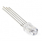
- 1x Common Cathode RGB LED
- 1x SparkFun Sound Detector Board
- 9x Jumper Wires
Didn't Get the SIK?
If you are conducting this experiment and didn't get the SIK, we suggest using these parts:


You will also need either an Arduino 101 OR Genuino 101 board.

Arduino 101
DEV-13787
Genuino 101
DEV-13984Suggested Reading
Before continuing with this experiment, we recommend you be familiar with the concepts in the following tutorials:
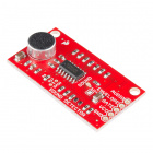
Introducing the Sound Detector Board

The Sound Detector Board is a nifty little sensor! It is a microphone circuit that saves you quite a bit of wiring. Once you attach the board to power (3.3V) on the VCC pin and ground to GND pin, there are three options for different signals to use as inputs for the 101.
The first signal, GATE, is a digital signal that turns on when the ambient sound passes a certain threshold. GATE also has an LED wired to it on the Sound Detector. Once you power it up correctly and make noise, you will see the red LED light up when it is "loud" and turn off when it is "quiet."
The second signal, ENVELOPE, scales the amplitude (how loud it is) to a 0-1023 10-bit value. In a quiet living room this level registers at about 10.
The final signal is the raw AUDIO signal. In a quiet room, the signal levels out around 512 and will produce a waveform curve based on the frequency of the ambient sound. The raw AUDIO signal would be something to use if you were looking to do some audio processing that is beyond the scope of this guide. To learn more about the specifics of the Sound Detector Board, please check out our hookup guide for it.
Hardware Hookup
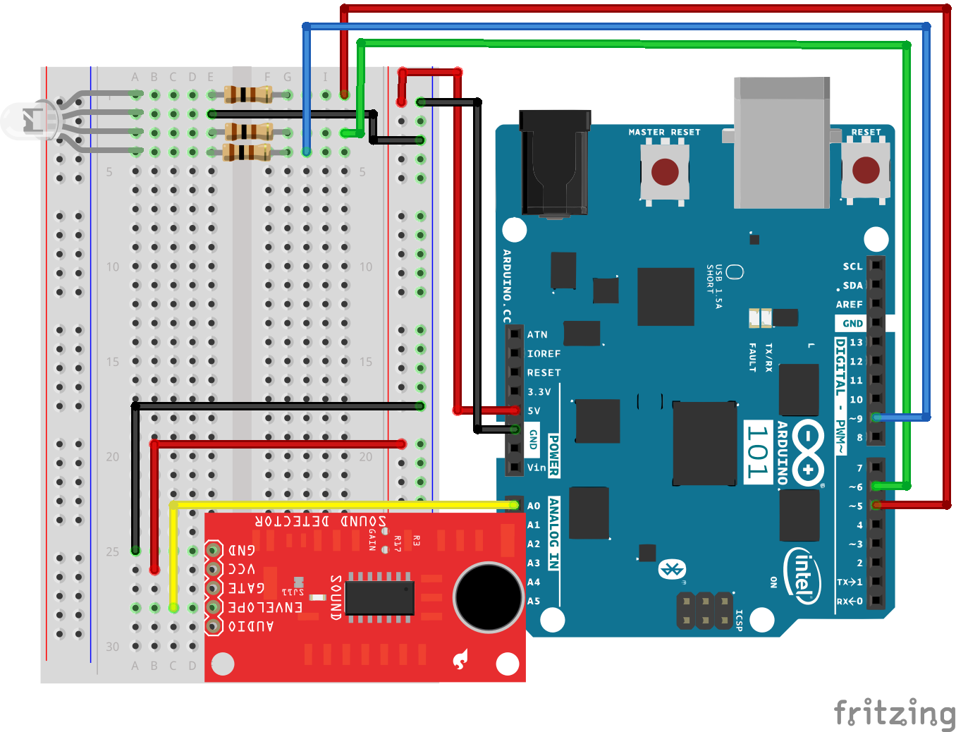
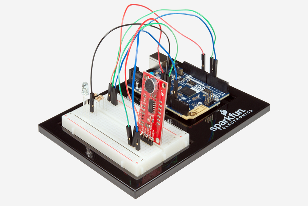
Ready to start hooking everything up? Check out the wiring diagram below to see how everything is connected.
| Polarized Components | Pay special attention to the component’s markings indicating how to place it on the breadboard. Polarized components can only be connected to a circuit in one direction. |
Wiring Diagram for the Experiment
Open the Sketch
Open the Arduino IDE software on your computer. Coding in the Arduino language will control your circuit. Open the code for Circuit 15 by accessing the “101 SIK Guide Code” you downloaded and placed into your “Examples” folder earlier.
To open the code go to: File > Examples >101 SIK Guide Code > Circuit_15
You can also copy and paste the following code into the Arduino IDE. Hit upload, and see what happens!
language:cpp
/*
SparkFun Inventor's Kit
Example sketch 15

SOUND DETECTOR

Use the sound detector to measure the volume of the surrounding area and change the
color of an RGB based on that volume.

 //pin variables
const int redPin = 5;
const int greenPin = 6;
const int bluePin = 9;
const int soundPin = 0;

//variables for storing raw sound and scaled value
int sound;
int scale;

void setup()
{
 //start the serial port a@ 9600bps
 Serial.begin(9600);
 //set RGB pins to OUTPUT
 pinMode(redPin, OUTPUT);
 pinMode(greenPin, OUTPUT);
 pinMode(bluePin, OUTPUT);
}

void loop()
{
 //read and store the audio from Envelope pin
 sound = analogRead(soundPin);
 //map sound which in a quiet room a clap is 300
 //from 0 to 3 to be used with switch case
 scale = map(sound, 0, 300, 0, 3);

 //print values over the serial port for debugging
 Serial.print(sound);
 Serial.print("   ");
 Serial.println(scale);

 //switch case on scaled value
switch (scale)
{
//if 0 RGB = Blue
case 0:
  digitalWrite(redPin, LOW);
  digitalWrite(greenPin, LOW);
  digitalWrite(bluePin, HIGH);
  break;
//if 1 RGB = Green
case 1:
  digitalWrite(redPin, LOW);
  digitalWrite(greenPin, HIGH);
  digitalWrite(bluePin, LOW);
  break;
//if 2 RGB = Yellow
case 2:
  digitalWrite(redPin, HIGH);
  digitalWrite(greenPin, HIGH);
  digitalWrite(bluePin, LOW);
  break;
//if 3 RGB = Red
case 3:
  digitalWrite(redPin, HIGH);
  digitalWrite(greenPin, LOW);
  digitalWrite(bluePin, LOW);
  break;
//default off
default:
  digitalWrite(redPin, LOW);
  digitalWrite(greenPin, LOW);
  digitalWrite(bluePin, LOW);
  break;
 }
}
Code to Note
scale = map(sound,0,300,0,3
This may seem like an odd mapping of values. This is a setup for using the switch case, and we need to map a large set of values down to three to four choices. The map function works both ways, but it comes in most handy to build ranges of values paired with a switch case.
switch(value)
{
 case(0):
 //do something
 break;
 case(1):
 //do something else
 break;
 default:
 //do another thing
 break;
}
Switch case comes in really handy when you think you are going to need a really long chain of if else() statements where you are trying to do something based on a range of values. Switch() looks at a variable and then looks for its match within a list of cases. If the match is not available it uses a default setting. Each case also has its own break command, which allows Arduino to escape out of the switch case and continue on its way.
What You Should See
Once the code is uploaded and the sketch starts, the RGB should turn blue. Make a lot of noise, and the RGB should change from blue to green and then to yellow ... if you get really loud it may turn red! Don't worry; we won't call the cops!
Troubleshooting
Not Getting Yellow or Red
Open up your serial monitor to do some debugging. Check your quiet value and then make a bunch of noise. Adjust your map function to make sure your range is the same.
Odd Values Coming from the Sound Detector
Make sure you have the sound detector board hooked up to 3.3V and you are reading the Envelope pin.
Still Not Working
Sometimes the Arduino 101 board will disconnect from the computer. Try unplugging and then replugging it into your USB port.