SIK Experiment Guide for the Arduino 101/Genuino 101 Board
 D___Run___
 Experiment 6: Reading a SPDT Switch
Introduction
In the previous experiment you used a button as a digital input. In this experiment you are going to explore another digital input, the SPDT (Single Pole - Double Throw) switch. You will use that switch to select which of the two LEDs will blink.
Parts Needed
You will need the following parts:
- 1x Breadboard
- 1x Arduino 101 or Genuino 101 board
- 2x LED (1 Red, 1 Yellow)
- 2x 100Ω Resistor
- 8x Jumper Wires
- 1x SPDT Switch
Didn't Get the SIK?
If you are conducting this experiment and didn't get the SIK, we suggest using these parts:


You will also need either an Arduino 101 OR Genuino 101 board.

Arduino 101
DEV-13787
Genuino 101
DEV-13984Suggested Reading
Before continuing with this tutorial, we recommend you be somewhat familiar with the concepts in these tutorials:
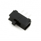
Introducing the Single Pole - Double Throw (SPDT) Switch

The Single Pole - Double Throw (SPDT) switch has a common pin in the middle and then two other pins that, depending on the location of the switch, are either connected to the common (center) pin or not. To read the switch in a similar way to a button, you connected the common pin to a digital General Purpose Input/Output (GPIO) pin on your 101 board and the other pins to 3.3V and ground. It doesn’t matter which pin is which. When you move the switch, the common pin will either be HIGH (connected to 3.3V) or LOW (connected to ground).
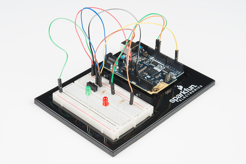
Hardware Hookup
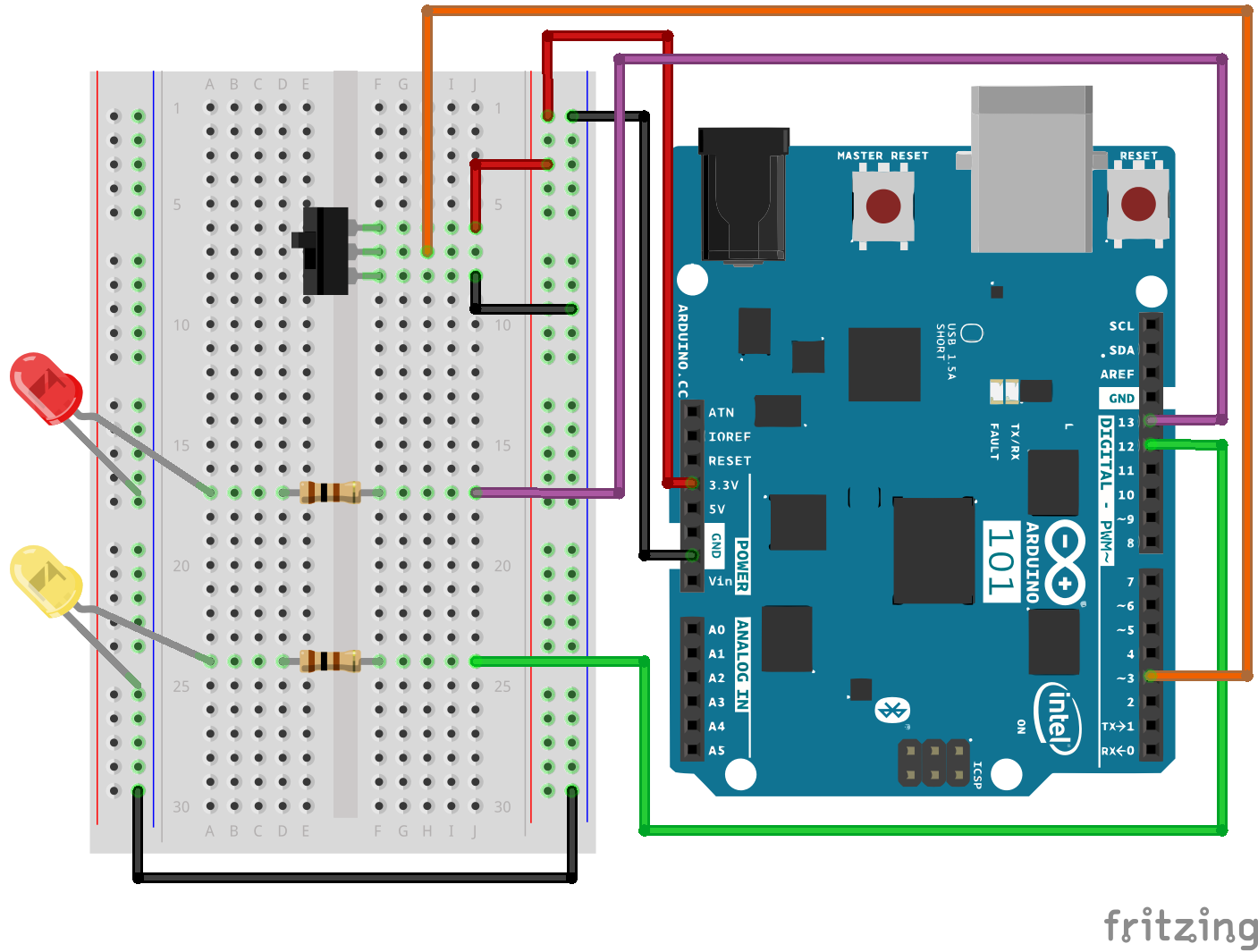
Ready to start hooking everything up? Check out the wiring diagram and hookup table below, to see how everything is connected.
| Polarized Components | Pay special attention to the component’s markings indicating how to place it on the breadboard. Polarized components can only be connected to a circuit in one direction. |
Wiring Diagram for the Experiment
Open the Sketch
Open the Arduino IDE software on your computer. Coding in the Arduino language will control your circuit. Open the code for Circuit 6 by accessing the “101 SIK Guide Code” you downloaded and placed into your “Examples” folder earlier.
To open the code go to: File > Examples > 101 SIK Guide Code > Circuit_06
You can also copy and paste the following code into the Arduino IDE. Hit upload, and see what happens!
language:cpp
/*
SparkFun Inventor's Kit
Example sketch 06

SPDT Switch

Use a Single Pole - Double Throw Switch (SPDT) to select an LED to blink

This sketch was written by SparkFun Electronics,
with lots of help from the Arduino community.
This code is completely free for any use.
Visit http://learn.sparkfun.com/products/2 for SIK information.
Visit http://www.arduino.cc to learn more about Arduino.
*/


// Create constants for the pins we will be using
const int switchPin = 3;
const int led1Pin = 12;
const int led2Pin =  13;


void setup()
{
  // Set up the switch pins to be an input:
  pinMode(switchPin, INPUT);

  // Set up the LED pins to be an output:
  pinMode(led1Pin,OUTPUT);
  pinMode(led2Pin,OUTPUT);
}


void loop()
{
  // variables to hold the switch state
  int switchVal;

  // Since a switch has only two states, either HIGH (3.3V)
  // or LOW (GND) there is no way for you to have a floating point situation so there       //is no need for a pulldown resistor.

  //store the switch value to the switchVal variable
  switchVal = digitalRead(switchPin);

 //if switchVal is HIGH blink led1Pin
 if(switchVal == HIGH)
 {
   digitalWrite(led1Pin,HIGH);
   delay(500);
   digitalWrite(led1Pin,LOW);
   delay(500);
 }
 //else blink led2Pin
 else
 {
   digitalWrite(led2Pin,HIGH);
   delay(500);
   digitalWrite(led2Pin,LOW);
   delay(500);
 }
}
Code to Note
pinMode(switchPin, INPUT);
The digital pins can be used as inputs as well as outputs. Before you do either, you need to tell the Arduino 101 which direction you're going.
switchVal = digitalRead(switchPin);
To read a digital input, you use the digitalRead() function. It will return HIGH if there's 3.3V present at the pin, or LOW if there's 0V present at the pin.
if (switchVal == LOW)
Because we've connected the button to GND, it will read LOW when it's being pressed. Here we're using the "equivalence" operator ("==") to see if the button is being pressed.
What You Should See
Depending on the state of the switch, a different LED will blink. If you move the switch to connect the signal pin to 3.3V (HIGH) then LED 1 will blink. If you flip the switch and ground the signal pin then LED 2 will start blinking and LED 1 will turn off.
Troubleshooting
Light Not Turning On
The wires for the switch are right next to each other. Make sure that signal is in the center with voltage and ground on the outside pins. If you connect ground and voltage your board will short out and shut down.
Make sure your power LED is on. If it is off, pull the signal wire from pin 3 and see if that changes anything. If you short circuit your 101 board it will turn itself off to protect the circuitry. You may also have to restart your computer to regain access to your serial port.
Underwhelmed
No worries; these circuits are all super stripped-down to make playing with the components easy, but once you throw them together the sky is the limit.