Soil Moisture Sensor Hookup Guide
 Sarah Al-Mutlaq,
  Joel_E_B, Ell C
 Introduction
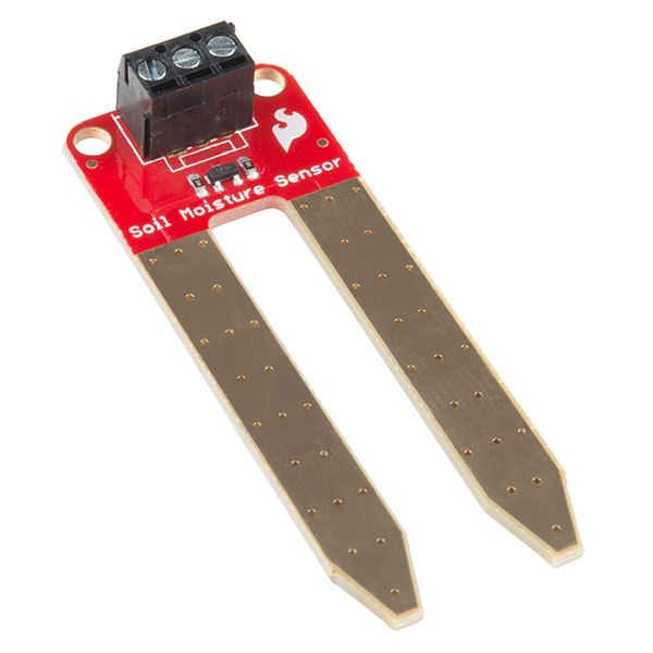
Have you ever wanted your plants to tell you when they need watered? Or know how saturated the soil in your garden is? With the SparkFun Soil Moisture Sensor, you can do just that! This tutorial will show you how to get started using the Soil Moisture Sensor as well as how to build your own soil moisture sensing project. If you prefer not to solder, you can purchase the sensor with a 3-pin screw terminal pre-soldered onto the board.
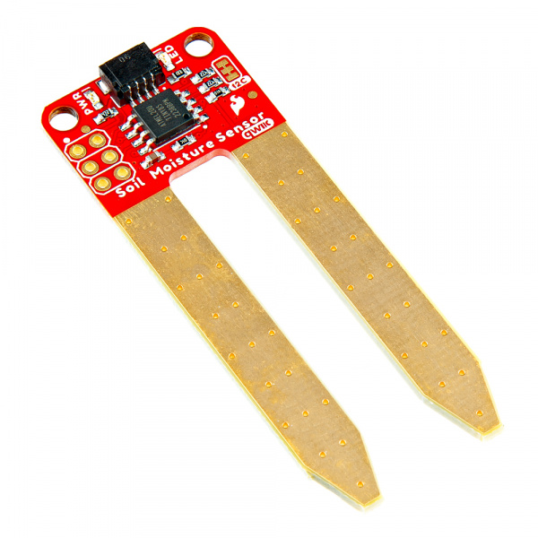
And if you're really in a hurry, use our plug-and-play Qwiic Soil Moisture Sensor!
Required Materials
To follow along with the project at the end of this tutorial, you will need the following. You may not need everything, though, depending on what you already have and which sensor you prefer. Add it all to your cart with the button below and modify as necessary.
Suggested Readings
There isn't much to learning how to use the Soil Moisture Sensor. However, you may find the following concepts useful along the way.
How to Solder: Through-Hole Soldering
Voltage, Current, Resistance, and Ohm's Law
Analog to Digital Conversion
Resistors
Soil moisture-sensing by hacking a solar light
If you aren't familiar with the Qwiic system, we recommend reading here for an overview should you decide to use the Qwiic version.
| Qwiic Connect System |
Hardware Overview and Assembly
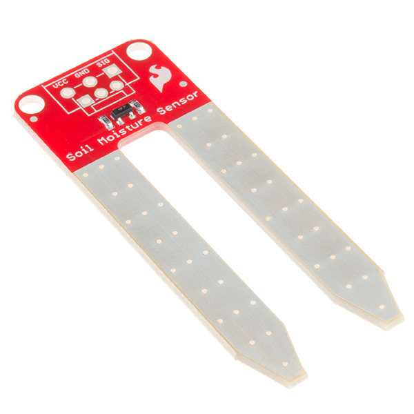
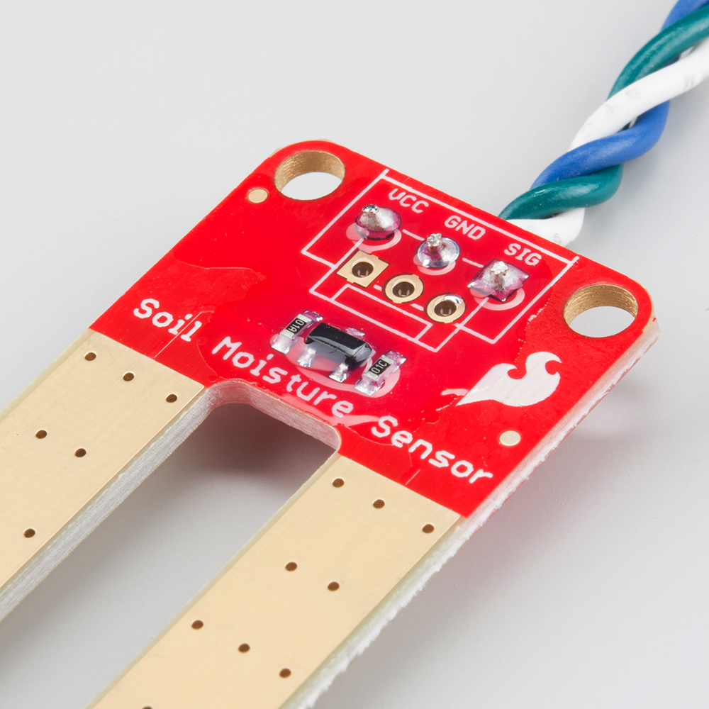
Our original Soil Moisture Sensor is pretty straightforward when it comes to hookup. There are only three pins to connect: VCC, GND, and SIG.
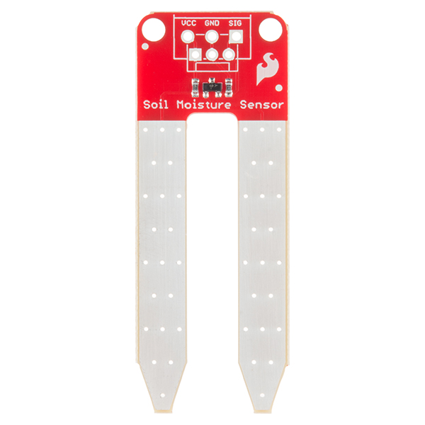
You need to supply power to VCC and GND. We recommend not powering the sensor constantly to prevent corrosion of the probes (more on this in a bit). SIG provides an analog signal out that can be attached to the ADC pin on any microcontroller. The value read on SIG will vary depending on the voltage with which you power the sensor.
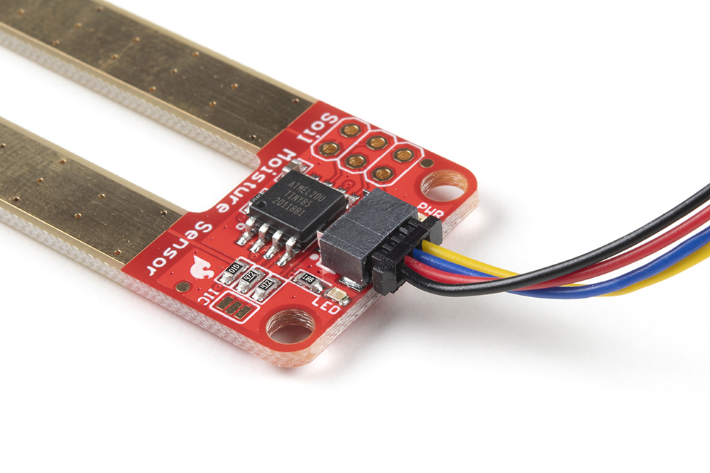
Qwiic Enabled Soil Moisture Sensor
Our Qwiic Soil Moisture Sensor utilizes the I2C protocol with the existing signals and the ATtiny85 MCU as the I2C gateway, which does all the nitty gritty stuff for you. The default I2C address is 0x28. The Qwiic connector should be self-evident, and this board also has pins broken out for SPI programming.
Note: Like our other Qwiic boards, the Qwiic Soil Moisture Sensor comes equipped with pull-up resistors for normal operation. If you are running multiple Qwiic devices on the same circuit, you will want to disable the pull up resistors by using an X-acto knife to cut the joint between the highlighted I2C jumper pads.
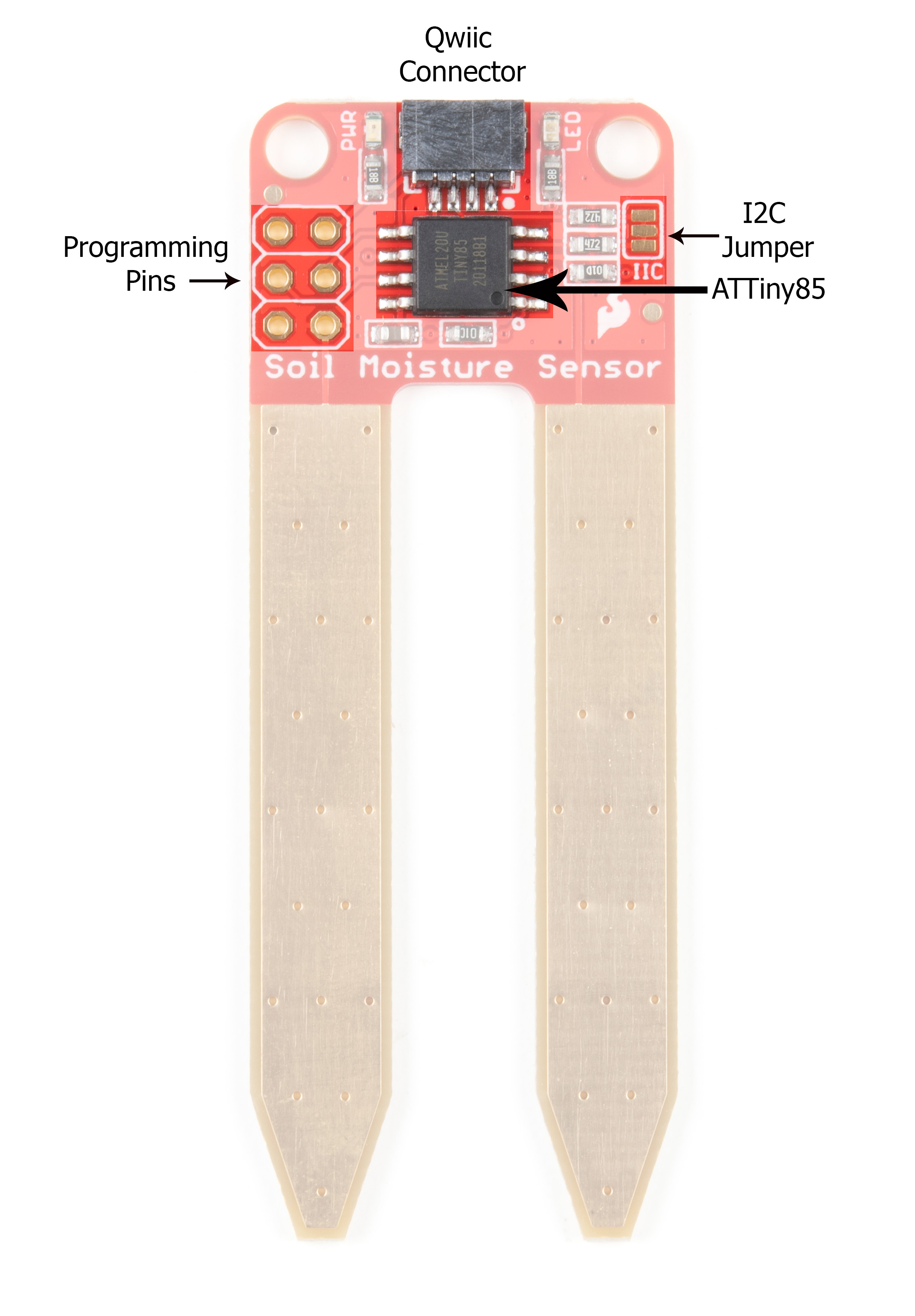
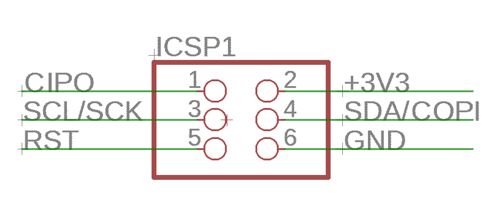
Programming Pins
For those of you who are interested in the Qwiic system but aren't quite set up yet, there are pins broken out such that you can use I2C or SPI protocols. See the image below for pin functionality.
Theory of Operation
The two probes are acting as a variable resistor – more water in the soil means better conductivity and results in a lower resistance and a higher SIG out. Your analog readings will vary depending on what voltage you use for Vcc as well as the resolution of your ADC pins.
Powering the Soil Moisture Sensor
If you're using Qwiic to power your board, then you're good to go. Otherwise, we recommend powering the Soil Moisture Sensor with between 3.3V - 5V. Please note that the analog value returned will vary depending on what voltage is provided for the sensor.
One commonly known issue with soil moisture sensors is their short lifespan when exposed to a moist environment. To combat this, we've had the PCB coated in Gold Finishing (Electroless Nickel Immersion Gold).
Another way to extend the lifespan of your sensor is to only power it when you take a reading. Using a digital pin set to HIGH on an Arduino, for example, is an easy way to accomplish this. If you wish to power the sensor with more than a digital pin on your microcontroller can provide, you could always use a transistor.
Assembly
If you bought the Soil Moisture Sensor that already has the 3-pin screw terminal attached, you may skip this section. Likewise, if you are using the Qwiic connector!
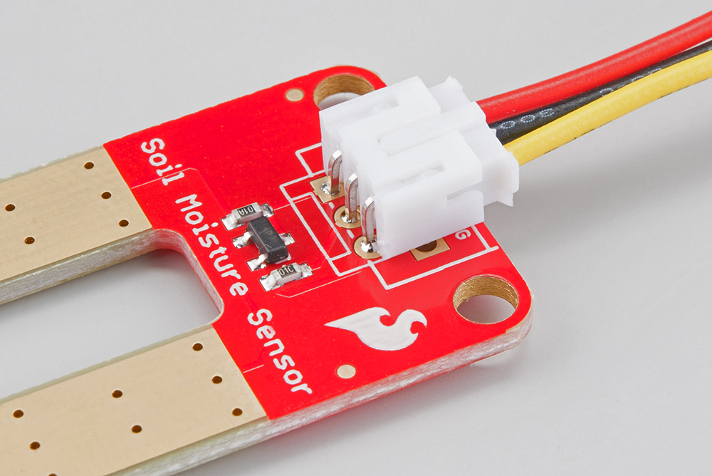
There are a few different options for connecting the sensor to your circuit. You can solder on a 3-pin JST Jumper Wire Assembly if you need to easily switch sensors on your project. This pairs nicely with our JST to Breadboard Jumper connector.
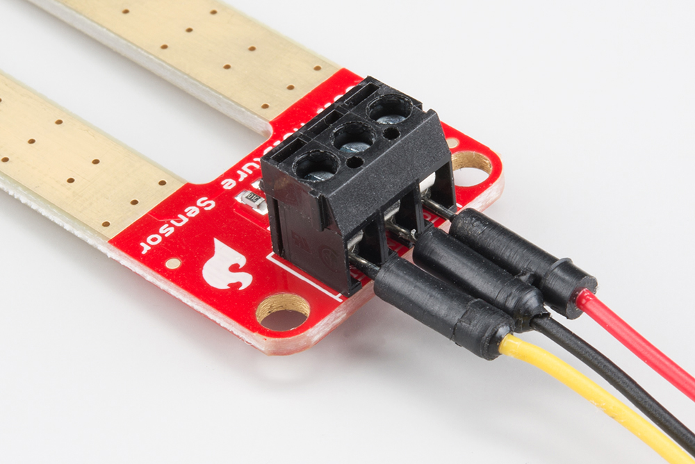
Another option is to solder on a 3-pin 3.5mm Screw Pin Terminal for a slightly more robust connection.
Of course, you can always solder some hookup wire straight to the sensor.
If you've opted for the Qwiic version of this board, assembly is a breeze.
Weatherproofing
If you intend to use this sensor outdoors, we recommend adding a little protection to the PCB to extend its lifespan. You could always use good ol' fashioned hot glue. However, hot glue does not hold up well in the sun and is only recommended for projects that will not be exposed to high temperatures. For projects that need to be able to withstand all the elements, you could use a conformal coating to cover the SMD parts on the PCB as well as your solder connections.
Soil Moisture Sensing Basic Example
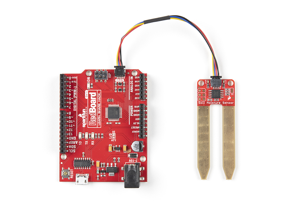
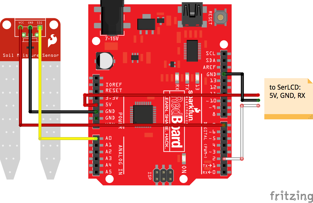
For this first example, we will connect the sensor to a RedBoard or other Arduino-compatible board in a minimalist fashion to show its output over the serial terminal.
Connect your Soil Moisture Sensor to your board as shown in the diagram below.
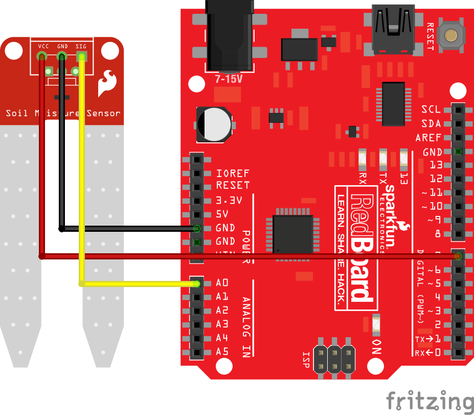
Once the circuit is built, upload the following code to your RedBoard or Arduino.
language:c
/*  Soil Moisture Basic Example
    This sketch was written by SparkFun Electronics
    Joel Bartlett
    August 31, 2015

    Basic skecth to print out soil moisture values to the Serial Monitor

    Released under the MIT License(http://opensource.org/licenses/MIT)
*/

int val = 0; //value for storing moisture value
int soilPin = A0;//Declare a variable for the soil moisture sensor
int soilPower = 7;//Variable for Soil moisture Power

//Rather than powering the sensor through the 3.3V or 5V pins,
//we'll use a digital pin to power the sensor. This will
//prevent corrosion of the sensor as it sits in the soil.

void setup()
{
  Serial.begin(9600);   // open serial over USB

  pinMode(soilPower, OUTPUT);//Set D7 as an OUTPUT
  digitalWrite(soilPower, LOW);//Set to LOW so no power is flowing through the sensor
}

void loop()
{
Serial.print("Soil Moisture = ");
//get soil moisture value from the function below and print it
Serial.println(readSoil());

//This 1 second timefrme is used so you can test the sensor and see it change in real-time.
//For in-plant applications, you will want to take readings much less frequently.
delay(1000);//take a reading every second
}
//This is a function used to get the soil moisture content
int readSoil()
{

    digitalWrite(soilPower, HIGH);//turn D7 "On"
    delay(10);//wait 10 milliseconds
    val = analogRead(soilPin);//Read the SIG value form sensor
    digitalWrite(soilPower, LOW);//turn D7 "Off"
    return val;//send current moisture value
}
Note that in the code, we are powering the soil moisture sensor with a digital pin on the RedBoard, not directly from 3.3V or 5V. Since this is a 5V device, the digital IO pins have a HIGH voltage of ~5V.
Once the sketch is uploaded, open a Serial Monitor window to see the output from the RedBoard. You should see a value at or close to 0 when the sensor is not touching anything. To see it sense moisture, you can grab both probes with your hand. The moisture from your body will be enough for the sensor to detect.
Further Examples
The Qwiic version of this board was built in cooperation with Zio Smart Prototyping. They've got some great examples in their Qwiic Soil Sensor GitHub Repository, which we've forked here.
The Qwiic Soil Moisture Sensor can be connected to a Qwiic Redboard as shown here:
Additional Projects
To connect your plant monitor to the Internet of Things, check out this experiment from our SparkFun Inventor's Kit for Photon. In it, we show how to connect the soil moisture sensor to an Internet connected device such as the Photon or the SparkFun Photon RedBoard.
You can also learn how to use the soil moisture sensor with the Blynk app in the Blynk Experiment Guide. Get plant watering notifications right on your phone or other mobile device!
Check out this great Instructables project from Circuito.io that uses the SparkFun Soil Moisture Sensor:
Calibration
System Calibration
To get any sort of useful data out of your Soil Moisture Sensor, it is advised that you calibrate it to whatever soil you plan to monitor. Different types of soil can affect the sensor, and you may get different readings from one composition tot he next. Before you start storing moisture data or triggering events based on that value, you should see what values you are actually getting from your sensor. Using the sketch above, note what values your sensor outputs when the sensor is completely dry vs when the sensor is completely submerged in a shallow cup of water. Depending on what microcontoller you're using, the operating voltage of that microcontoller, and the resolution of its analog-to-digital converter, you're results will vary.
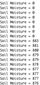
For example, using the same circuit above, if I detach the VCC pin from D7 and attach it directly to the 5V supply on the RedBoard, you'll see the close to the following values in the serial monitor when the sensor is dry (~0) and when it is completely saturated with moisture (~880).
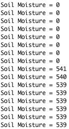
But, if I take the VCC pin and connect it to the 3.3V supply on the RedBoard, the values change. As expected, they get lower since there is less resolution between 0V and 3.3V than there is between 0V and 5V.
Thus, it is difficult to write an example sketch that works for all platforms. It really depends on the operating voltage and ADC resolution of the board you're using.
Soil Calibration
Once you have an idea what values your sensor is outputting in completely dry and completely wet situations, it's time to calibrate your sensor for the specific soil you want to monitor. Do the same test above, only this time test your soil when it is as dry as possible, then measure it when the soil is completely saturated with moisture. Getting these values and comparing them to the ones from the previous calibration will give you the best insight into what values mean for your specific plant and soil. This test may take some trial and error and patience. Be careful not to over-water (or under-water) your plants during these tests.
Once you have a good handle on the values you can expect, you can use the map() function to adjust your code accordingly.
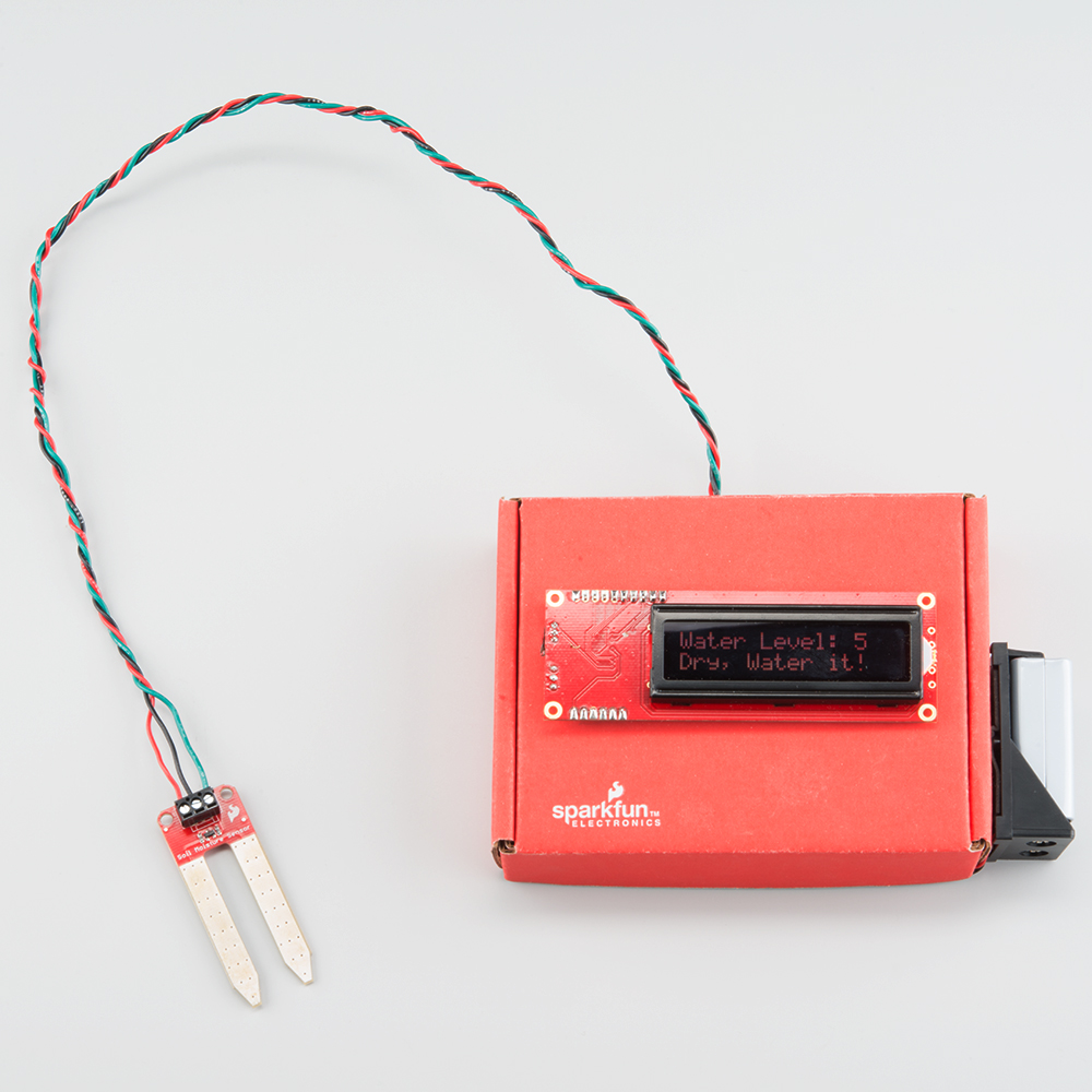
Soil Moisture Sensing Project
For this next example, we're going to make a portable soil moisture sensor that will print the current moisture value to an LCD screen. We'll use the circuit from the previous example. This time we just need to add a Serial Enabled LCD Screen and portable power.
Hook up your circuit as pictured below:
Along with the soil moisture sensor, we have connected the LCD screen to 5V, GND, and digital pin 2 (D2) for serial communication (also can be changed in the code).
Feel free to put your circuit in an enclosure of some sort. A SparkFun red box makes for a great project box. For this project, we are powering the ReadBoard with a 9V battery and 9V battery holder to make it portable.
The code for this is fairly straightforward. You will need the Software Serial library to interact with the serial LCD screen. If you do not have this library you can get it from the Arduino GitHub here. If you have never uploaded a library or want a quick refresher on how to do that, check out our tutorial here. Installation should not be necessary, as this library now comes with the Arduino IDE by default.
For more specific information about the code, you can read the comments in the code itself:
language:c
// SparkFun Soil Moisture Sensor and Serial LCD example 1
// By Sarah Al-Mutlaq 2015
// Sketch reads sensor and desplays level and whether soil is wet or dry

// Use the softwareserial library to create a new "soft" serial port
// for the display. This prevents display corruption when uploading code.
#include <SoftwareSerial.h>

// Attach the serial display's RX line to digital pin 2
SoftwareSerial mySerial(3,2); // pin 2 = TX, pin 3 = RX (unused)


// Here we are setting up some water thersholds that we will
// use later. Note that you will need to change these to match
// your soil type and environment.

/********************************************************
 * Change these values based on your calibration values
 *******************************************************/
int thresholdUp = 400;
int thresholdDown = 250;

// We are setting up the pin A0 on the redboard to be our sensor
// pin input:

int soilPin = A0;
int soilPower = 7;//Variable for Soil moisture Power

void setup(){
  mySerial.begin(9600); // set up serial port for 9600 baud (speed)
  delay(500); // wait for display to boot up

  pinMode(soilPower, OUTPUT);//Set D7 as an OUTPUT
  digitalWrite(soilPower, LOW);//Set to LOW so no power is flowing through the sensor
}

void loop(){
  // Here we are declaring a string, which are lines of words,
  // and we want DisplayWords to be the words displayed on
  // the LCD screen, which will change based on whether the soil
  // wet or dry based on our threshold values above.
  String DisplayWords;

  // We need to set up a pin to get the value that the soil
  // moisture sensor is outputting, so sensorValue will get the
  // analog value from the sensor pin A0 on the redboard that we
  // set up earlier.

  int sensorValue;
  sensorValue = readSoil();

  // move cursor to beginning of first line on LCD:
  mySerial.write(254);
  mySerial.write(128);

  // clear display:
  mySerial.write("                ");
  mySerial.write("                ");

  // move cursor to beginning of first line of the LCD screen:
  mySerial.write(254);
  mySerial.write(128);

  //Write what we want to desplay on the screen:
  mySerial.write("Water Level: ");
  mySerial.print(sensorValue); //Using .print instead of .write for values

  // Now we are going to check if the water level is below a
  // out thresholdDown value we set earlier, and if it is have
  // words "Dry, Water it!" display one column over on the first
  // row:

  if (sensorValue <= thresholdDown){
    // move cursor to beginning of second line on LCD:
    mySerial.write(254);
    mySerial.write(192);

    DisplayWords = "Dry, Water it!";
    mySerial.print(DisplayWords);

  // If the value is not below our thresholdDown value we want to
  // check if it is above our thresholdUp value, and if it is
  // change the display words to "Wet, Leave it!":


  } else if (sensorValue >= thresholdUp){
    // move cursor to beginning of second line on LCD:
    mySerial.write(254);
    mySerial.write(192);

    DisplayWords = "Wet, Leave it!";
    mySerial.print(DisplayWords);

  // Otherwise if it is inbetween the two values we want it to
  // the display it had, so if our soil was really wet and drying
  // the words would only change to "Dry, Water it!" when it got to the lower threshold
  // (thresholdDown), but if it was dry and getting wetter the words
  // would only change to "Wet, Leave it!" when it got to the upper
  // threshold (thresholdUp_):

  } else {
    // move cursor to beginning of second line on LCD:
    mySerial.write(254);
    mySerial.write(192);

    mySerial.print(DisplayWords);
  }

  delay(500); //wait for half a second, so it is easier to read
}

//This is a function used to get the soil moisture content
int readSoil()
{
    digitalWrite(soilPower, HIGH);//turn D7 "On"
    delay(10);//wait 10 milliseconds
    int val = analogRead(soilPin);//Read the SIG value form sensor
    digitalWrite(soilPower, LOW);//turn D7 "Off"
    return val;//send current moisture value
}
This code has different values for an upper threshold and a lower one, so you have a middle zone that could either be wet or dry depending on whether the soil is drying out (coming down from being wet) or getting wet (coming up from being dry). If you don't want this middle zone, you can set both thresholds to the same value, but I have found that having this middle area is more similar to how soil actually works; there really isn't a point at which soil goes from being wet to dry. If you are interested in soil and how it reacts to water, you should read up on it; it can be very complicated and interesting.
You will need to adjust the code variables anyway, since this will be unique to your setup, soil type, and how wet you actually want your soil to be. Using the calibration techniques mentioned above, test out the reading and play around with the values until you find some that fit your needs.
Troubleshooting
If you need technical assistance and more information on a product that is not working as you expected, we recommend heading on over to the SparkFun Technical Assistance page for some initial troubleshooting.
If you don't find what you need there, the SparkFun Forums are a great place to find and ask for help. If this is your first visit, you'll need to create a Forum Account to search product forums and post questions.
Resources and Going Further
For more information, check out the links below:
SparkFun Soil Moisture Sensor (13322):
SparkFun Soil Moisture Sensor with Screw Terminals (13637):
SparkFun Qwiic Soil Moisture Sensor(17731):
- Schematic (PDF)
- Eagle Files (ZIP)
- Qwiic Soil Moisture Sensor GitHub
- Atmel ATTiny Datasheet
- Qwiic Resource Page
Zio:
Still want more? Check out these other great SparkFun tutorials for more soil moisture sensing fun!