Smart Home Expansion Kit for Arduino 101
Experiment 9: Using a Current Sensor
Introduction
In Experiment 1 you gained ultimate control over being able to turn on and off appliances that plug into the wall through the use of the IoT Relay. But you didn't have a way to determine if the appliance was on, off or even plugged in, let alone the ability to track how much current it was using. Well, that is all going to change with this experiment!
In this experiment you are going to learn about the Non-Invasive Current Sensor (NICS). The NICS clips around a single wire of an extension cord that is plugged into the power cord of any appliance and, with some basic wiring, will enable you to track the amount of current a given appliance is consuming at that moment without having to mess with exposed AC high-voltage wiring. You will be building a device that you can plug a device or appliance into to measure the number of watts that it uses. This is great for figuring out what appliances are using how much power, and later this circuit is a great way to detect if a device is on or off by way of monitoring how many watts it pulls.
Parts Needed
You will need the following parts:
- 1x Breadboard (From your Arduino 101 SIK)
- 1x Arduino 101 Board (From your Arduino 101 SIK)
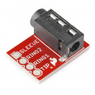
- 1x TRRS Connector Breakout
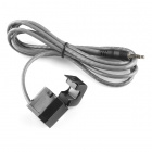
- 1x Passive Current Sensor
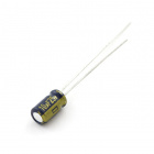
- 1x 10 uF Capacitor
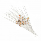
- 2x 10k Ohm Resistor (From your Arduino 101 SIK)
- 1x 100 Ohm Resistor (From your Arduino 101 SIK)
- 7x Jumper Wires (From your Arduino 101 SIK)
- 1x Air Conditioner Extension Cord, 3' (Amazon)
Didn't Get the Around-the-Home Expansion Kit?
If you are conducting this experiment and didn't get the Around-the-Home Expansion Kit, we suggest using these parts:
Headers or No Headers?
Note:If you are buying the breakout boards (TRRS Breakout) seperate from this kit you will also need to buy female breakaway pins and assemble (solder) the pins to your board yourself.Arduino 101
DEV-13787Suggested Reading
Before continuing with this experiment, we recommend you be familiar with the concepts in the following tutorials:
- Light-Emitting Diodes --- Learn more about LEDs
- Switch Basics --- Learn more about buttons and switches
Introducing the Current Sensor
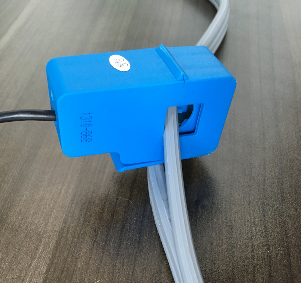
The Non-Invasive Current Sensor (NICS) has a "jaw" that clamps around a wire. It can read the amount of current flowing through the wire without the wire itself having to be modified (ergo, non-invasive). By an appliance into an extension cord and then using the current sensor to detect how much current is going through the extension cord, we'll be able to tell when the AC is running.
The current sensor's output is a current much lower than, but linearly related to, the current it's sensing.
TRRS Breakout
The NICS has a connector that looks like an audio jack on one end. It is a TRS (Tip-Ring-Sleeve) connector, shown on the left side of the diagram below. You may also have seen TRRS connectors (Tip-Ring-Ring-Sleeve, right side of diagram), which are commonly used for hands-free headsets. The TRRS breakout makes each of the pieces of a TRRS connector (the tip, each of the two rings and the sleeve) accessible. The TRRS breakout will allow us to easily connect to the tip and the sleeve of the current sensor's connector so we can read its values.
OK, now that we have figured out the new parts at the party, let's build the circuit!
Hardware Hookup
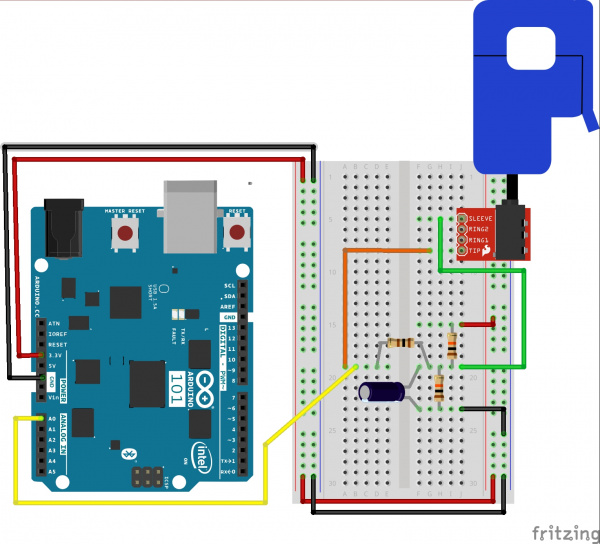
Ready to start hooking everything up? Check out the wiring diagram below to see how everything is connected.
Wiring Diagram for the Experiment
To hook the current sensor up to the extension cord you'll need a sharp utility knife and a safe, clean cutting surface. On your surface, lay the Air Conditioner Extension Cord flat, and use the utility knife to separate one of the three joined sections of wire. Make the cut approximately 3 to 4 inches long—just long enough to put the current sensor's top "jaw" through and safely clip it together.
Build Your Blynk App
In creating this app you will build a gauge that will display the wattage of the device you are measuring in real time, as well as a graph of the time that your phone is connected to it. So, you can see where you are and where you have been (short term) --- and watch the wattage use over the time that you are watching.
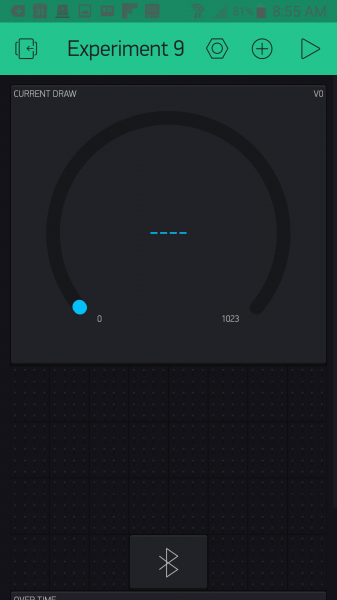
As with all of the Blynk apps that use the Arduino 101 board, add the BLE widget and open the settings to connect your phone to the Arduino 101. Once you have added the BLE widget, you can start to add the other widgets for this app. We start out by bringing the gauge widget into your app and opening the widget settings. This gauge will display the wattage draw from the NICS, which we will be writing to pin V0.
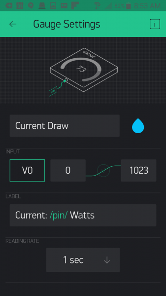
Open the settings of your gauge. Name your gauge (we labeled ours "Wattage") and set the pin to pin V0. For this we also changed the value range to 0--20, as we probably wouldn't be pulling 1023 amps from an appliance. The last setting is the Label for the gauge, which we set as "Wattage: /pin/ Watts". We placed the gauge and resized it so that it is the dominant view of the app. With that we are done with the gauge.
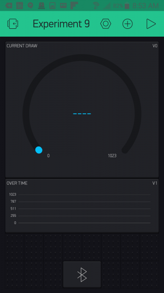
After adding the gauge, you can now add the graph widget and place it below the gauge as shown below.
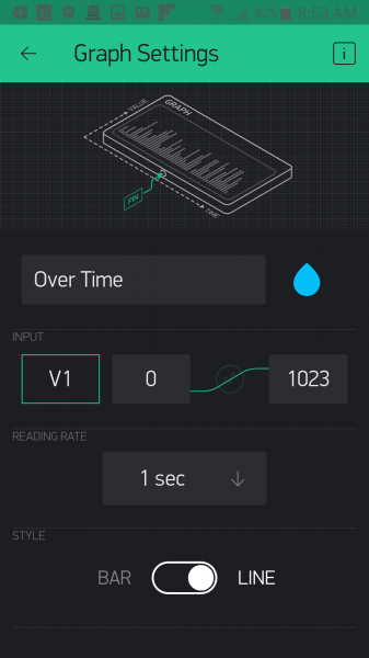
Now, open the graph widget settings. We named our graph "Over Time" as it will display the Wattage use over the time that you have the app opened. We set the pin to pin V1 as we cannot point two widgets at the same virtual pin at the same time; we will fix this in our sketch! In terms of the value range we changed the standard 0--1023 to 0--4000 since these values will be in watts and not a 10-bit (0--1023) number. After doing some extensive research (Google) we found that a dishwasher can consume around 3600 watts, so we aimed for a little higher than that. Finally, we changed the style to Line. With that we are done with the app!
Uploading Your Sketch
Open the Arduino IDE software on your computer. Coding in the Arduino language will control your circuit.
You can type out or copy and paste the following code into the Arduino IDE. Hit upload, and see what happens!
language:cpp
/********************************************************************************
SparkFun Around-The-Home SIK Expansion Kit, Experiment 9
SparkFun Electronics
Product URL

Build a device to measure the power useage of an applicance around your home and then display it in a Blynk app.

This example is written by: Derek Runberg, Educational Technologist

This sketch was written by SparkFun Electronics, with lots of help from the Arduino community.
This code is completely free for any use.

View circuit diagram and instructions at:https://learn.sparkfun.com/tutorials/around-the-home-expansion-kit

********************************************************************************/

/* Comment this out to disable prints and save space */
#define BLYNK_PRINT Serial
#include <BlynkSimpleCurieBLE.h>
#include <CurieBLE.h>
#include <math.h>

BLEPeripheral  blePeripheral;


// You should get Auth Token in the Blynk App.
// Go to the Project Settings (nut icon).
char auth[] = "YOUR_AUTH_TOKEN";


const int CURRENT_SENSOR_PIN = A1;
const int LED_PIN = 13;

int  currentWatts;
int calibratedWattage;

void setup()
{
  blePeripheral.setLocalName("Exp_09");
  blePeripheral.setDeviceName("Exp_09");
  blePeripheral.setAppearance(384);

  Blynk.begin(blePeripheral, auth);
  blePeripheral.begin();

  Serial.begin(9600);

// Setup notification button on pin 2  pinMode(REPLAY_PIN, OUTPUT);
  calibratedWattage = getWatts(CURRENT_SENSOR_PIN);
}

void loop()
{
  currentWatts = getWatts(CURRENT_SENSOR_PIN);
  Serial.println(currentWatts);

  if(currentWatts > calibratedWattage){
    digitalWrite(LED_PIN, HIGH);
  }
  else{
    digitalWrite(LED_PIN, LOW);
  }
  blePeripheral.poll();
  Blynk.run();
}

float getWatts(int pin) {

  // RMS voltage
  const double vRMS = 120.0;      // Assumed or measured

  // Parameters for measuring RMS current
  const double offset = 1.65;     // Half the ADC max voltage
  const int numTurns = 2000;      // 1:2000 transformer turns
  const int rBurden = 100;        // Burden resistor value
  const int numSamples = 1000;    // Number of samples before calculating RMS

  int sample;
  double voltage;
  double iPrimary;
  double acc = 0;
  double iRMS;
  double apparentPower;

  // Take a number of samples and calculate RMS current
  for ( int i = 0; i < numSamples; i++ ) {

  // Read ADC, convert to voltage, remove offset
  sample = analogRead(pin);
  voltage = (sample * 3.3) / 1023;
  voltage = voltage - offset;

  // Calculate the sensed current
  iPrimary = (voltage / rBurden) * numTurns;

  // Square current and add to accumulator
  acc += pow(iPrimary, 2);
  }

  // Calculate RMS from accumulated values
  iRMS = sqrt(acc / numSamples);

  // Calculate apparent power and return it
  apparentPower = vRMS * iRMS;
  return apparentPower;
}

//write the real time current draw of the fan when read from the app
BLYNK_READ(V0) {
  //read current sensor

  Blynk.virtualWrite(0, currentWatts);
}

BLYNK_READ(V1) {
  Blynk.virtualWrite(1, currentWatts);
}
Code to Note
This sketch is by far the heaviest sketch in terms of programming. The good thing is that most of it is collecting readings and calculating equations. We wrapped all of the complicated math into the getWatts() function to give you the option of taking a closer look at how we did it and changing it for your own situation...or just using it out of the box!
language:cpp
int  currentWatts;
int calibratedWattage;
We started out by creating two global variables: one stores the current watts calculated by the Arduino 101 board later in the sketch, and the other stores a calibration value, which is just a single wattage reading in the setup() --- that way we have a starting point to compare to.
calibratedWattage = getWatts(A0);
To get a calibration value we just call the getWatts(A0) function in setup() and store it in the callibrationWattage variable. This only happens once at power-up, so if you want to recalibrate you can use the RESET button on the Arduino 101 board, or power cycle the board.
language:cpp
// RMS voltage
const double vRMS = 120.0;      // Assumed or measured
const double offset = 1.65;     // Half the ADC max voltage
const int numTurns = 2000;      // 1:2000 transformer turns
const int rBurden = 100;        // Burden resistor value
const int numSamples = 1000;    // Number of samples before calculating RMS
Inside of the getWatts() function there are a number of variables that are used to calculate the wattage output of the function and using the NICS. A couple of them that you will need to manipulate depending on your use are:
const double vRMS = 120.0;--- If you are in Europe or measuring an outlet that is higher voltage, you will need to change this.const double offset = 1.65;--- If you are using a 5-volt board, this value should be 2.5.
language:cpp
// Take a number of samples and calculate RMS current
for ( int i = 0; i < numSamples; i++ ) {
// Read ADC, convert to voltage, remove offset
sample = analogRead(pin);
voltage = (sample * 3.3) / 1023;
voltage = voltage - offset;
// Calculate the sensed current
iPrimary = (voltage / rBurden) * numTurns;
// Square current and add to accumulator
acc += pow(iPrimary, 2);
}
// Calculate RMS from accumulated values
  iRMS = sqrt(acc / numSamples);
// Calculate apparent power and return it
apparentPower = vRMS * iRMS;
return apparentPower;
Here are the full calculations from taking the 10-bit analog value from reading pin A0 to calculating the voltage and so on. The comments in the code lead you through the full process. The main thing to note here is that when all is said and done, the function returns a float value using return apparentPower;
currentWatts = getWatts(A0);
In the loop we update the currentWatts variable using the getWatts() function.
language:cpp
BLYNK_READ(V0) {
  Blynk.virtualWrite(0, currentWatts);
}

BLYNK_READ(V1) {
  Blynk.virtualWrite(1, currentWatts);
}
Finally, we respond to the BYLNK_READ() event functions with the same response with a single change of what pin we write to since we cannot point both widgets at the single event...bummer!
Troubleshooting
Blynk Shortcut!
If you are having troubles duplicating the functionality above in the Blynk app, scan this QR code with Blynk to get a clone of this experiment!
Odd Numbers?
Make sure that you have hooked up the circuit correctly, especially the capacitors! Capacitors are highly polarized.
Still odd!
make sure the connection of the RTTS connector is fully inside of the breakout connector and that the sensor itself is correctly fastened around the wire to be read.


