Smart Home Expansion Kit for Arduino 101
 D___Run___
 Experiment 1: Hello, World...Again
Introduction
This experiment assumes that you have already gone through the SparkFun Inventor's Kit for the Arduino 101 Board. If you have not, we recommend at least going through the first few experiments here. But, we realize that it may have been awhile for you, so we are going to make sure that everything is up and running and that you can upload code to your Arduino 101 board. Yep, you guessed it: Hello, World...Again! But this time it's with a twist. Let's get blinking!
Parts Needed
You will need the following parts:
- 1x Arduino 101 Board (From your Arduino 101 SIK)
- 1x Breadboard (From your Arduino 101 SIK)
- 1x IoT Relay
- 2x Jumper Wires (From your Arduino 101 SIK)
Didn't Get the Around-the-Home Expansion Kit?
If you are conducting this experiment and didn't get the Around-the-Home Expansion Kit, we suggest using these parts:


Arduino 101
DEV-13787Suggested Reading
Before continuing with this experiment, we recommend you be familiar with the concepts in the following tutorial:
- Light-Emitting Diodes --- Learn more about LEDs
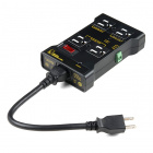
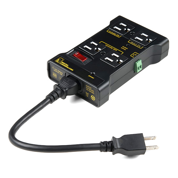
Introducing the IoT Relay
You have turned LEDs on and off, but have you ever wondered how you could use your Arduino 101 to turn bigger things --- like lamps, fans and even your refrigerator --- on and off? Enter the IoT relay!
The IoT relay looks like a simple power strip you would find around your home, but it has a few tricks up its sleeve. First of all you will notice that the plug receptacles are labeled. One is labeled "Normally On," and the other is "Normally Off." This allows you to do a couple of different things. First, you can control whether your GPIO logic from your Arduino is reverse (HIGH = OFF). Or, a little less apparent, is the ability to toggle two different appliances by toggling a GPIO pin. For example, if you plug two lamps in and leave both on, you can toggle which one is on and which one is off by toggling a GPIO pin.
You may ask yourself, "What GPIO pin?" The IoT relay has a screw terminal connection that you supply a signal wire that you can connect to any GPIO pin on your Arduino board, as well as a ground pin connected to the Ground pin on your Arduino. That's it! You can now control any appliance plugged into your IoT relay with an Arduino.
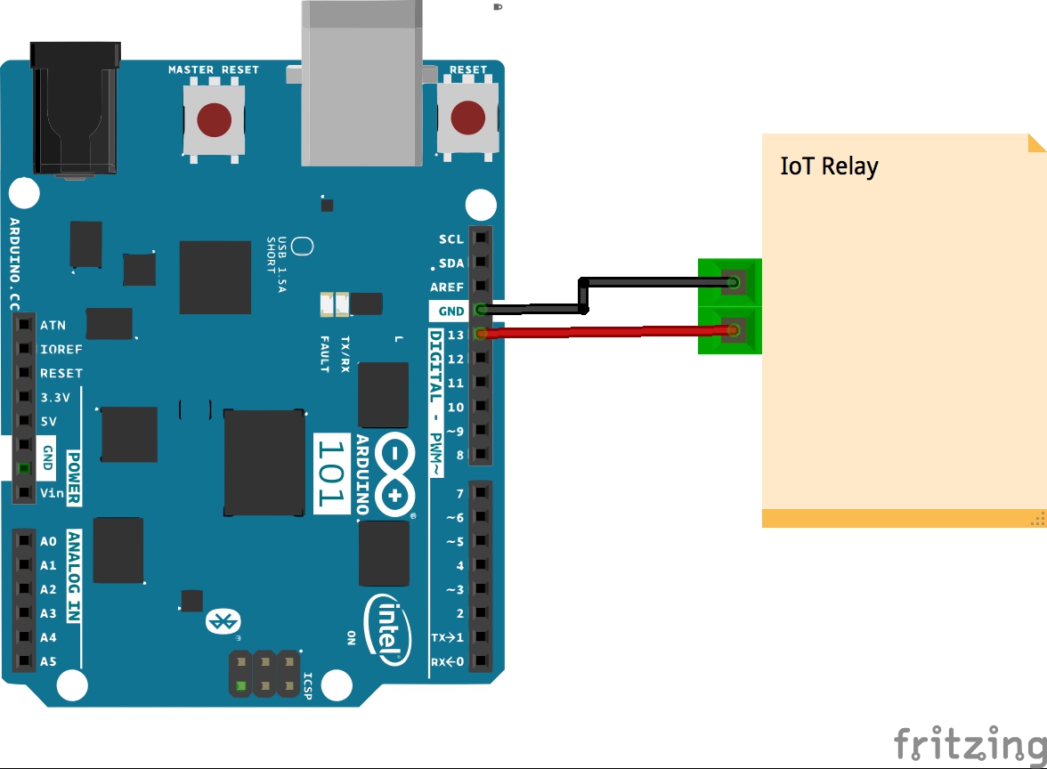
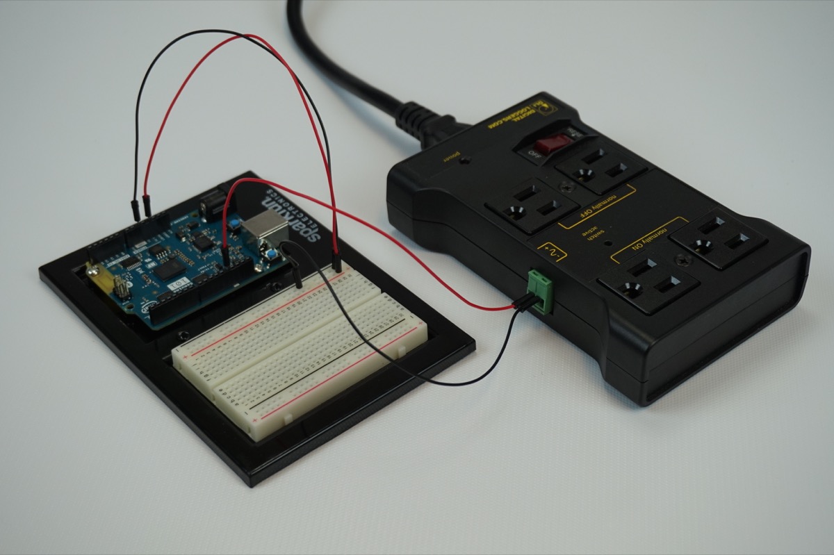
Hardware Hookup
Ready to start hooking everything up? Check out the wiring diagram below to see how everything is connected.
Wiring Diagram for the Experiment
Build Your Blynk App
The last part of this experiment is to build the app itself. You created it earlier to get an authorization token, but now you need to add widgets to be able to control your Arduino 101 board.
Open your Blynk app and navigate to the blank project that you created for this experiment.
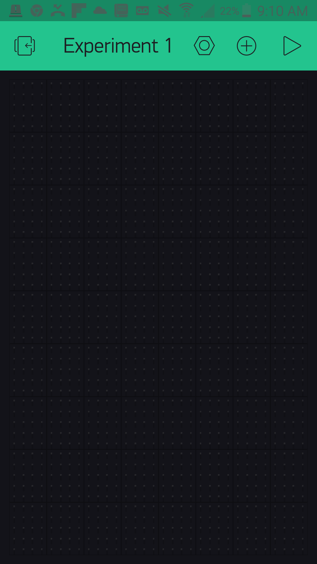
To control the IoT relay, which you have connected to pin 13, you are going to use the button widget in your app. To add the button widget press the (+) logo in the upper right-hand corner of the app. This will bring up a list of widgets as shown below.
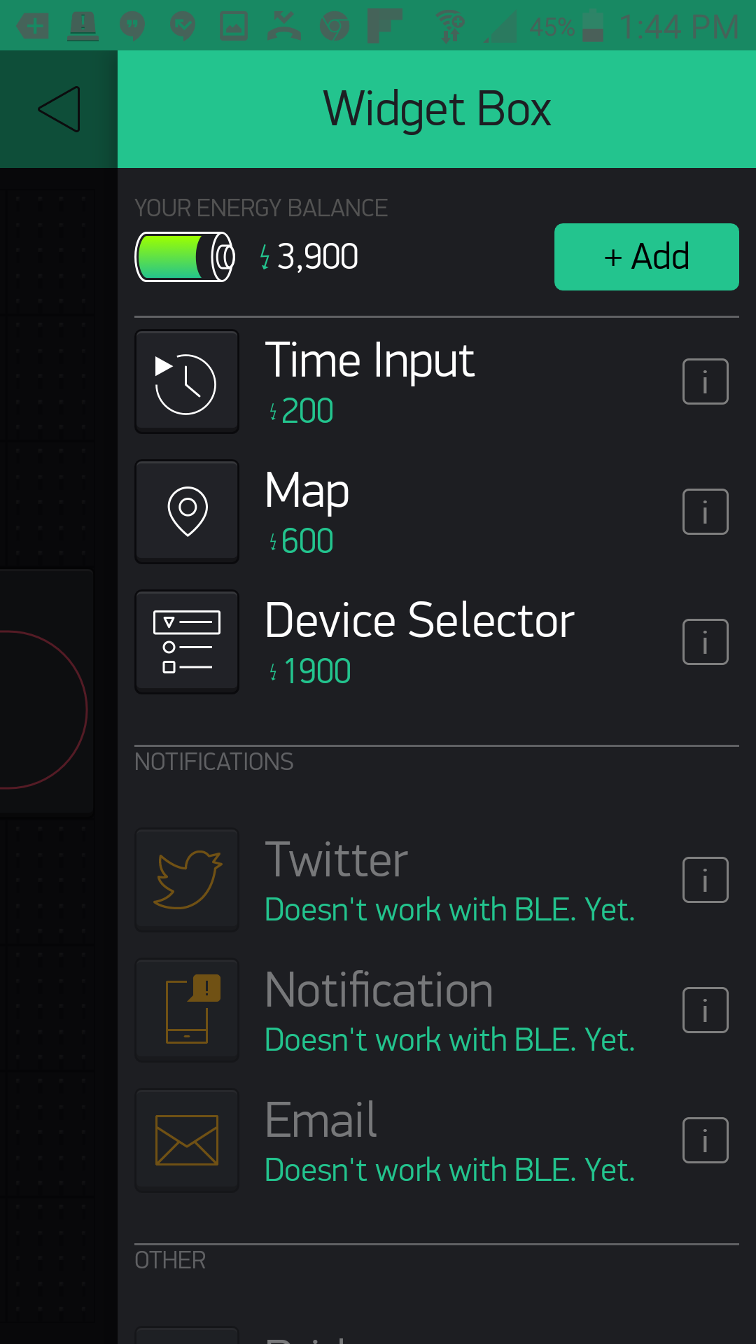
Select the Button widget, which will add it to your app. From there you can press and hold to drag the button around your app. Once you have placed it, you can also resize it to fit. We centered ours and made it full width.
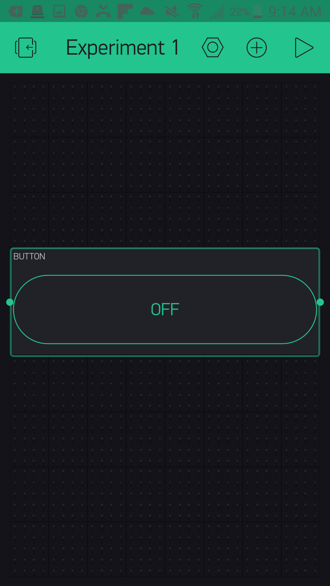
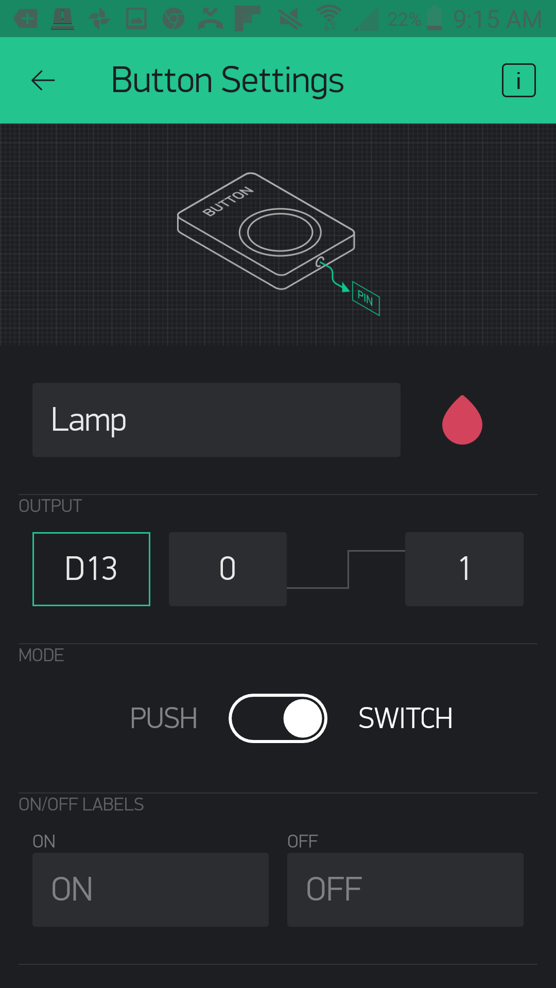
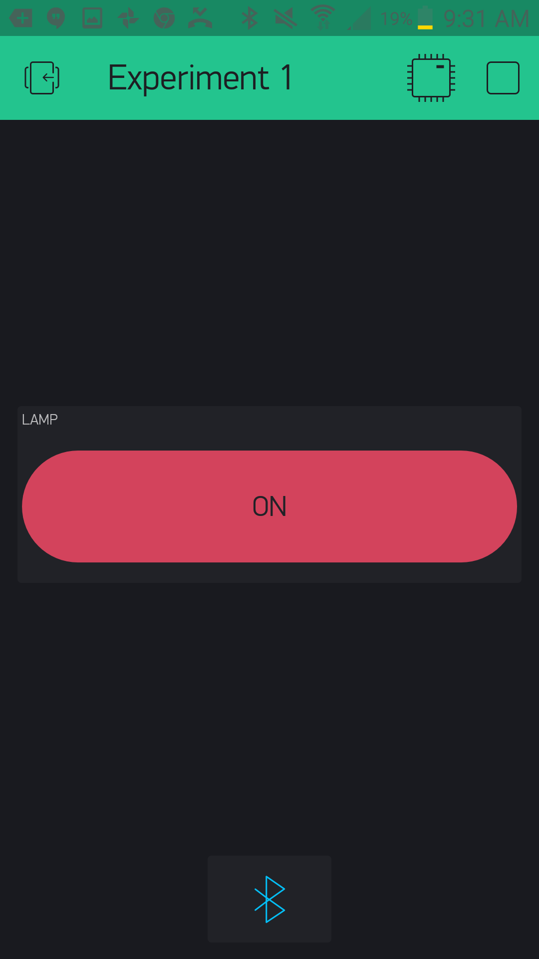
Now to make your button functional! Tapping on the button once will bring up the settings menu for that button. From here you can label the button --- we named ours "Lamp." You then assign the pin that you want it to control --- we chose "D13," or digital pin 13. There are a number of other pins you can use, and we will explore their types in later experiments. Lastly, we selected "switch" as out button functionality so that it stays on or off when we press the button.
With that you are done with the button! Click the back arrow in the upper left-hand corner.
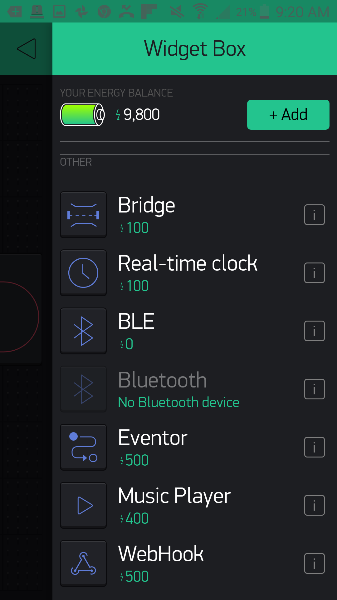
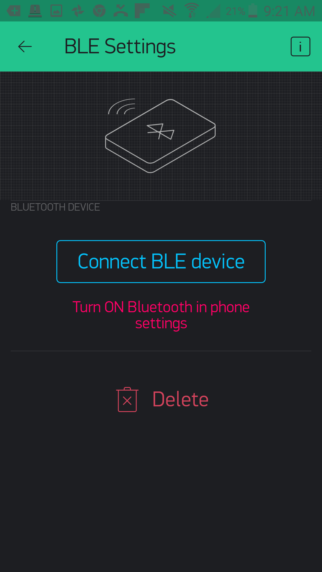
The last thing we need to do --- and something we will have to do with all of our Bynk apps that use the Arduino 101 with BLE --- will be to add the BLE widget to our app. Click the (+) button again and scroll down to find the BLE widget
Once you have placed it in your app, go ahead and tap it to open up the BLE settings. You will need to turn Bluetooth and location on in your device for this to work. Click "Connect BLE Device," and Blynk will search for your Arduino 101 board with the name you gave it in the sketch.
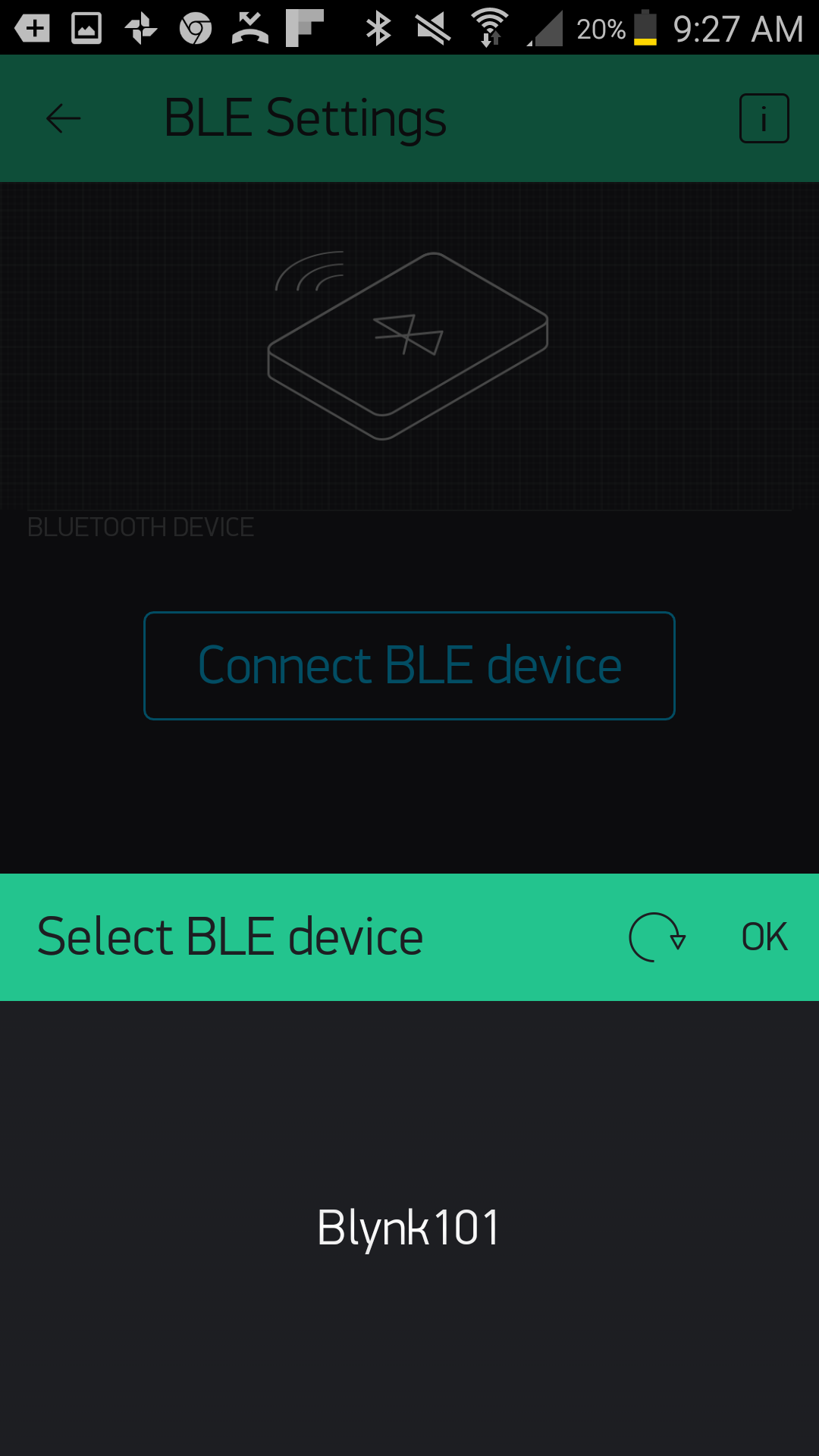
If everything works to plan, your Arduino 101 will show up in a list. Go ahead and select it. Your device will connect to your 101 board, and you should get confirmation of connection in the app.
You can now go back to your main app window and run your app by clicking on the play button in the upper right-hand corner. Once the app starts, you can click on the "Lamp" button, and the LED on the Arduino 101 board will turn on and off. But more importantly, whatever you have plugged into your IoT relay will turn on and off!
Before you go ahead and launch your app, be sure to upload the sketch to your Arduino 101 board first!
Upload Your First Sketch
Open the Arduino IDE software on your computer. To find this example/basic sketch to control circuits with Blynk in Arduino, navigate to File > Examples > Blynk > Boards_Bluetooth > Arduino_101_BLE
When you created your app in the previous section, an authorization token was automatically emailed to you. Check your inbox and have the token on hand; you will need to add it to your Arduino sketch before you upload it to your Arduino 101 board.
Replace "YourAuthToken" with your token. Make sure you keep it in quotes as a String; otherwise you will get an error when you try to compile your sketch.
You can also type out or copy and paste the following code into the Arduino IDE. Hit upload, and see what happens!
language:cpp
/********************************************************************************
SparkFun Around-The-Home SIK Expansion Kit, Experiment 1
SparkFun Electronics
Product URL

Controls the IoT relay with the Arduino 101 board through the use of the Blynk app.

This example is written by: Derek Runberg, Educational Technologist

This sketch was written by SparkFun Electronics, with lots of help from the Arduino community.
This code is completely free for any use.

View circuit diagram and instructions at:https://learn.sparkfun.com/tutorials/around-the-home-expansion-kit

********************************************************************************/


//#define BLYNK_USE_DIRECT_CONNECT

#define BLYNK_PRINT Serial

#include <BlynkSimpleCurieBLE.h>
#include <CurieBLE.h>

// You should get Auth Token in the Blynk App.
// Go to the Project Settings (nut icon).
char auth[] = "YourAuthToken";

//create a BLE peripheral object
BLEPeripheral  blePeripheral;

void setup() {
 //start the Serial port at 9600 baud
 Serial.begin(9600);
 //wait 1 second
 delay(1000);

 //give your project a local and device name
 blePeripheral.setLocalName("Exp_01");
 blePeripheral.setDeviceName("Exp_01");
 //set the BLE appearance
 blePeripheral.setAppearance(384);

 //start Blynk
 Blynk.begin(blePeripheral, auth);

 //start the BLE service
 blePeripheral.begin();

 Serial.println("Waiting for connections...");
}

void loop() {
 Blynk.run();
 blePeripheral.poll();
}
Code to Note
The basic blocks of this sketch focus on enabling the Bluetooth on your Arduino 101 board and setting up and running the Blynk firmware. This is the basic example sketch for using the Arduino 101 and BLE with Blynk, and throughout this experiment guide we will be using this as the foundation for other Blynk-based sketches to come. For the sake of reference, here are a few commands that you should have a solid understanding of for use with the experiments:
#define BLYNK_PRINT Serial
This define statement points the Blynk debug console to the Serial port on the Arduino 101. To see this feedback information, hook your Arduino 101 up to your computer using your USB cable and open your Serial monitor. You can all turn this off by commenting this statement out using // in front of the statement. This will help to speed up your sketch and save room.
char auth[] = "YourAuthToken";
When you build a Blynk app, it is assigned an authorization token that gets emailed to the email account attached to the Blynk app. To make sure your Arduino 101 board talks to your app and only your app, you need to replace "YourAuthToken" with your token inside quotes.
language:cpp
blePeripheral.setLocalName("Exp_01");
blePeripheral.setDeviceName("Exp_01");
These commands enable you to give your Arduino 101 board a name that it broadcasts to all BLE-enabled devices around it. As a default throughout this guide we will be using the experiment number, for this experiment it is named "Exp_01", but you can change it to whatever string you would like. We recommend changing both the local name and device name to the same name.
language:cpp
 Blynk.begin(blePeripheral, auth);
 blePeripheral.begin();
On the Arduino 101 board you need to start Blynk first and pass it the blePeripheral object and your authorization token. You then can start the BLE service on your Arduino 101 board.
language:cpp
void loop() {
 Blynk.run();
 blePeripheral.poll();
}
After all of that setup, the loop of this sketch is almost comically short. It contains two methods. The first one runs Blynk, which polls the app on your device and makes sure that it is in sync with what's happening on your board.
The second method does a similar action, but manages your BLE connection between the Arduino 101 and your phone or tablet.
That's it! Like we said, this is the foundation we will be using and adding to over the course of the next eight experiments.
What You Should See
Your lamp that you plugged in to the IoT Relay's "Normally On" plug should turn on and off when you press the button in your Blynk app! Try different appliances or add another lamp to the "Normally Off" plug and use the button to switch between the two different lamps.
Troubleshooting
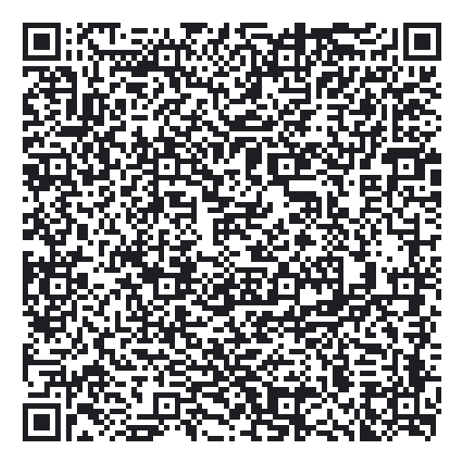
Blynk Shortcut!
If you are having troubles duplicating the functionality above in the Blynk app, scan this QR code with Blynk to get a clone of this experiment!
Program Not Uploading
This happens sometimes; the most likely cause is a confused serial port. You can change this in Tools > Serial Port >
Also, if you get a Timeout error or the IDE could not find your 101 board, try pressing the Master Reset button on the 101, wait about 10 seconds and try re-uploading your sketch.
Still No Success
A broken circuit is no fun. Send us an email, and we will get back to you as soon as we can: techsupport@sparkfun.com