RedBoard Plus Hookup Guide
 bboyho, santaimpersonator
 Introduction
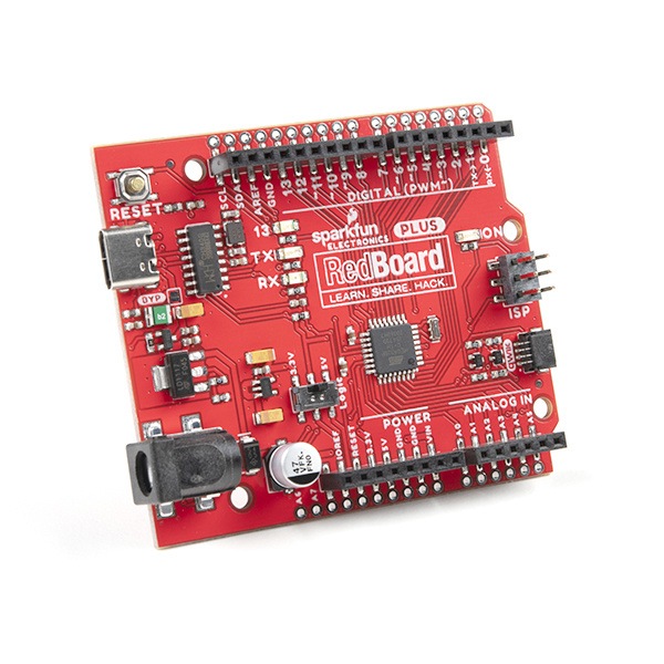
The SparkFun RedBoard Plus is an Arduino-compatible development board that combines the design from the classic RedBoard and RedBoard Qwiic. The RedBoard Plus incorporates a few key improvements over its predecessors (see Hardware Overview). However, like the original RedBoard, it is designed to be an easy-to-use learning platform for coding, physical computing, and project prototyping. These skills are becoming increasingly significant in today's education and the technological community.
This tutorial aims to familiarize you with the RedBoard Plus and help you get started using it. To begin, we'll guide you through the installation of the Arduino IDE (Integrated Development Environment) software, the main user interface for programming the board. Next, we will go over the hardware and features of the board. Finally, we will walk you through a few examples using the Arduino IDE.
The RedBoard Plus can interact with real-world sensors, control motors, display information, and perform near-instantaneous calculations. It enables anyone to create unique, nifty projects from something as simple as displaying characters on an LCD display or detecting changes in light to vastly more complicated projects like an IoT cellular device (Not recommend for beginners... start with something simpler and work your way up.). If you're familiar with how the original RedBoard and RedBoard Qwiic worked, you may want to skim over parts of this tutorial.
Required Materials
To get started, all you need is a few things. You may not need everything though depending on what you have. Add it to your cart, read through the guide, and adjust the cart as necessary.
- RedBoard Plus - You'll definitely need this; otherwise, you might be on the wrong tutorial (wink-wink).
- Reversible USB A to C Cable - 2m - The USB interface serves two purposes: it powers the board and allows you to upload programs to it.


Required Software
You will also need a computer with the Arduino IDE installed on it - That is how we will program the board and interface with it.
Suggested Tools and Peripherals
That is ALL... pretty simple right? Now you won't be able to do much since there are no additional sensors to interact with the physical world. However, you can at least blink an LED and do some math calculations.
Jumper Modification Qwiic Example
wish to perform. Feel free to modify the items in your cart to fit your needs.
Jumper Modification
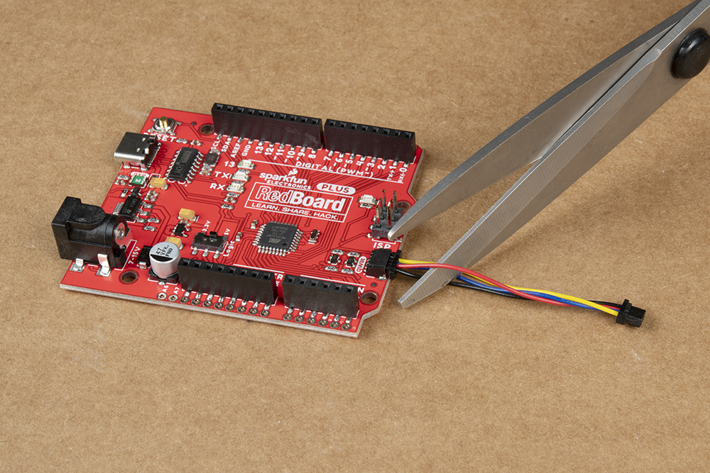
If you would like to modify the A4/A5 Qwiic connector jumpers, you will need soldering equipment and/or a knife.


Weller WLC100 Soldering Station
TOL-14228Qwiic Example
If you would like to follow along with the examples below to interact with the physical world, you will also need the following items: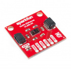

Qwiic Cable - 100mm
PRT-14427Suggested Reading
The RedBoard Plus aims to be a beginner-friendly microcontroller platform. You can get started without an innate knowledge of Ohm's Law or How Electricity Works (but a little understanding wouldn't hurt!). The following are some subjects you should be familiar with; however, to use the more advanced features of the board, it is recommended that you read up on the Logic Levels and I2C tutorials.
What is a Circuit?
What is an Arduino?
Logic Levels
I2C
One of the new, advanced features of the board is that it takes advantage of the Qwiic connect system. We recommend familiarizing yourself with the Logic Levels and I2C tutorials (above) before using it, as all Qwiic sensors utilize an I2C communication protocol. Click on the banner above to learn more about Qwiic products.
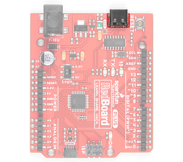
Hardware Overview
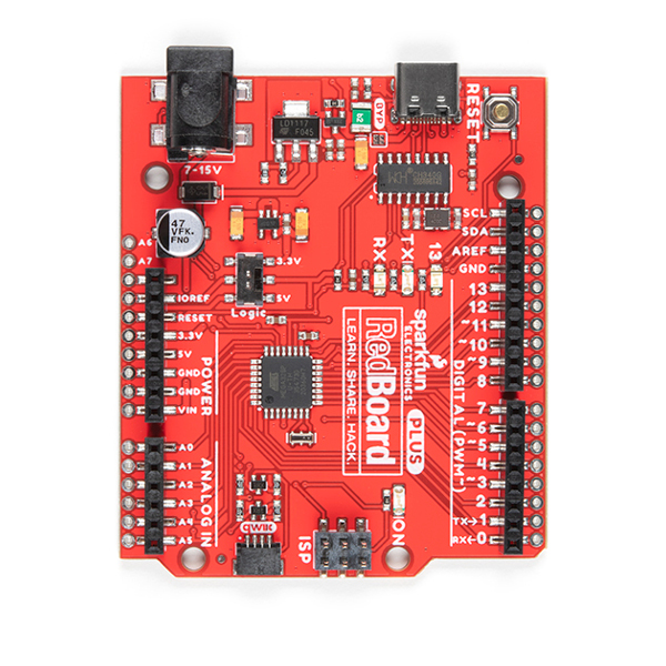
Below is the graphical datasheet of the board and an overview of all of the important features for the RedBoard Plus. All of the RedBoard Plus pins are broken out to 0.1" spaced female headers (i.e. connectors) on the outer edges of the board. The pins are grouped together for power inputs/outputs, analog inputs, and digital inputs.
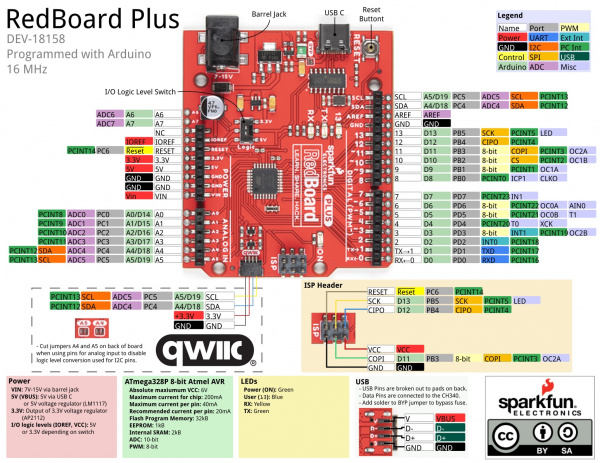
New Features
Building off the RedBoard Qwiic, the RedBoard Plus includes the following changes.
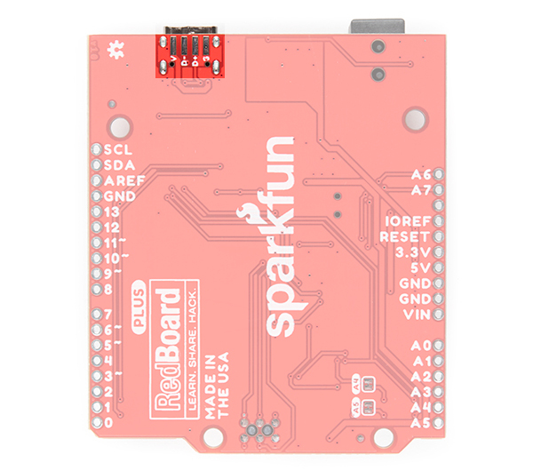
- USB Type C Connector - The RedBoard has seen many types of USB connectors. The RedBoard Plus takes advantange of the USB C connector. The pins are also broken out on the back of the board!
- Bypass Jumper - The board includes a jumper to bypass the resettable fuse.
- I/O Logic Switch - Instead of cutting a jumper pad and adding solder to the board, you can now flip the switch to adjust the logic level for the system voltage.
- Two More Analog Pins - Two additional analog pins are included for A6 and A7. Previous designs of the Uno R3 footprint on the RedBoard did not include the pins. These analog pins are included by the power pins as PTH pads.
- PTH Pads - All of the edge pins on the RedBoard Plus now include an additional PTH pad by each female header. This makes the board slightly wider but you have the advantage of soldering wires or additional header pins to the board.
 |
 |
| RedBoard Qwiic | RedBoard Plus |
Power
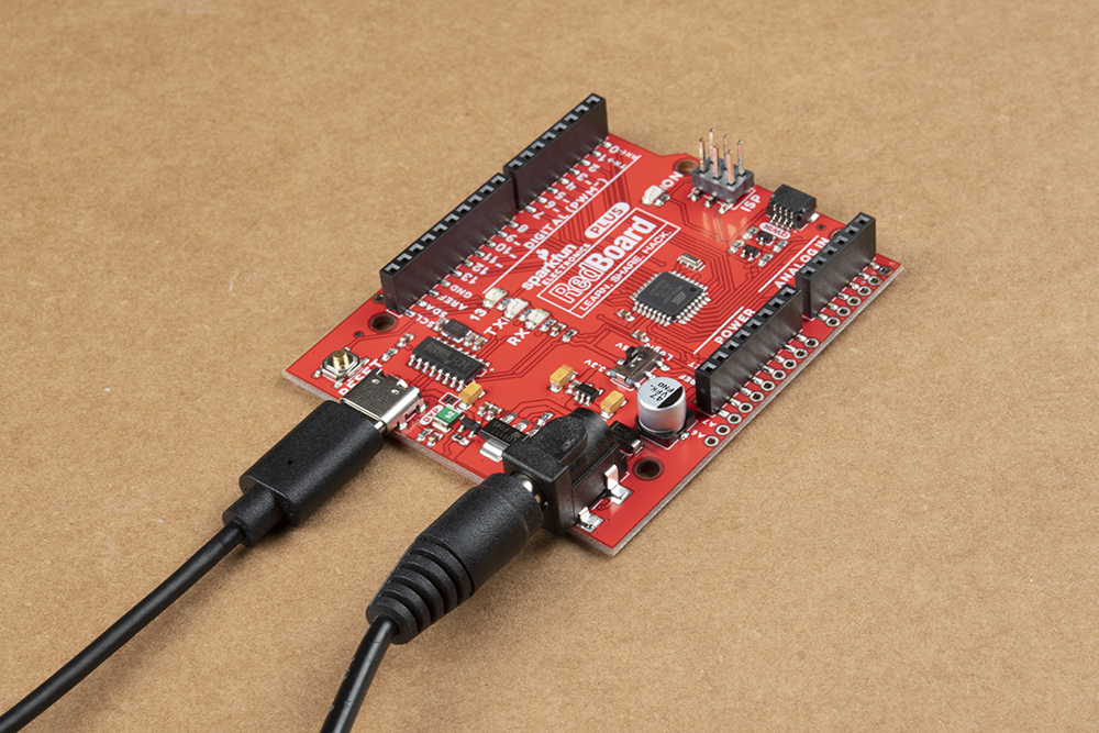
The RedBoard Plus can be powered via the USB and/or barrel jack connectors. If you choose to power it via USB, the other end of the USB cable can be connected to either a computer or a 5V (regulated) USB wall charger. Otherwise, should you choose to use the barrel jack, any wall adapter connected to this jack should supply a DC voltage between 7 and 15V. You could also power the board via the header pins.
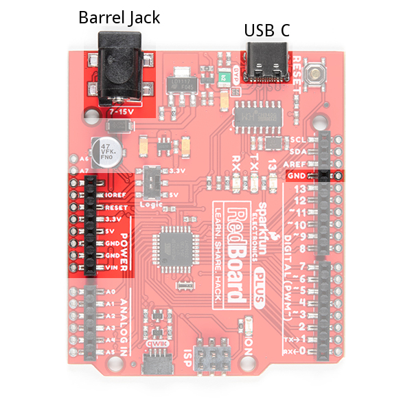
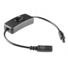
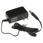
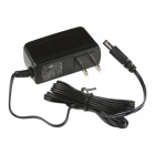
Barrel Jack
The barrel jack accepts a male, center-positive connector with a 5.5mm outer diameter and 2.1mm inner diameter. Check out this tutorial for more information on power connectors.
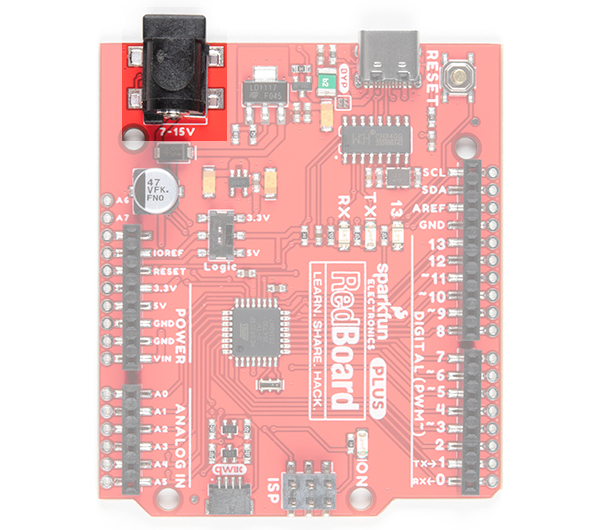
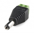
Our 9V and 12V power adapters are good choices if you're looking to power the board through the barrel jack. Any wall adapter connected to this jack should supply a DC voltage between 7 and 15V as specified by the electrical characteristics of the LM1117 voltage regulator used on the board. The input voltage pin VIN on the power headers is directly connected to the input voltage of the barrel jack. Depending on your project, you can also wire your own power supply with the DC barrel jack adapter or add a switch between your power supply and RedBoard Plus.
For more technical details about voltage regulators and thermal dissipation, I suggest taking a look at these blog posts and tutorial:
USB Power
A USB C cable is usually the easiest way to power the board, especially when you're programming it because the USB interface is required for uploading code too. The pins are broken out on the back of the board.
- V - USB input voltage. This should be 5V.
- D− and D+ - USB data pins. These are connected to the CH340 USB-to-serial converter.
- G - Ground pin
 |
 |
A traditional USB port supplies a regulated 5V, but is limited to about 500mA (USB 2.0). Additionally, there is a resettable fuse that protects your computer from shorts and overcurrent. If more than ~750mA is drawn through the USB port, it automatically throttles the current draw or disconnects power until the short/overload is removed. If you need more than that a barrel jack wall adapter is the best choice.
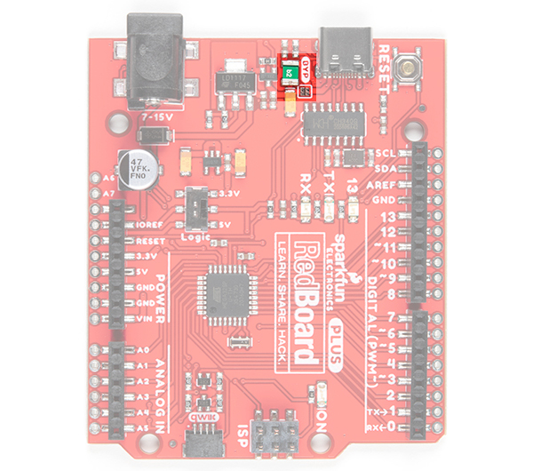
BYP Jumper
Next to the USB C connector is a bypass jumper (labeled as BYP). If you need to bypass the PTC fuse (rated for 6V max, 4A trip current) for any reason, you can add some solder to connect the jumper. This is recommended for advanced users that know what they are doing.
USB Programming
There are two ways to program the RedBoard Plus. As stated in the previous section, the most common way for users is through the USB connection. The other slightly less common method is through the ISP headers or pins.
The USB C connector is the most convenient way to power and program the board. To program the board through the USB connection, you will need a USB Type C cable and there must be a bootloader flashed to the microcontroller (factory "installed"). For the RedBoard Plus, this is the same Optiboot bootloader from the Arduino Uno R3. For most users, the board will be programmed through a USB connection using the Arduino IDE.
Dual Power
It is fine to connect both a barrel jack and a USB connector at the same time. The RedBoard Plus has power-control circuitry to automatically select the best power source.
AP2112 Voltage Regulator
The AP2112 uses a robust 3.3V regulator to provide more power to daisy chain multiple Qwiic (I2C) devices. Unlike the MIC5205 on the original RedBoard, which could only source about 150mA of current; the AP2112 can source up to 600mA of current and should be able to handle the needs of your Qwiic devices.
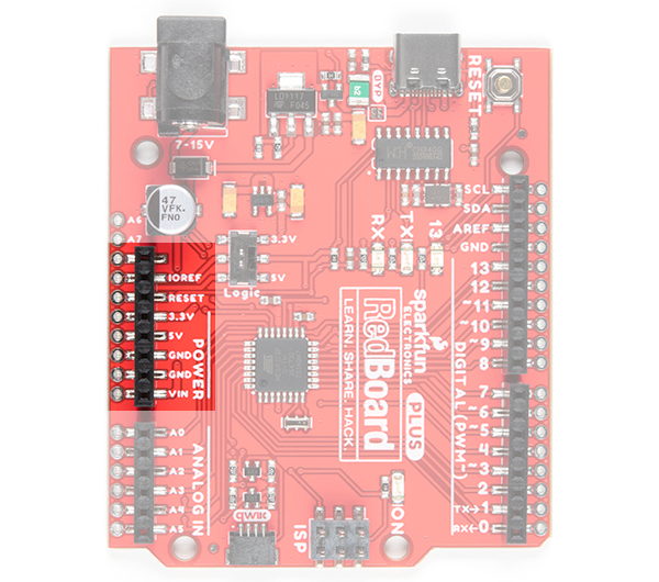
The Power Header
The power headers provides all your reference, input, and output voltages.
- IOREF - This pin is connected to the I/O logic level switch. The voltage will either be 3.3V or 5V depending on what voltage is selected. This pin provides the voltage reference for the microcontroller's I/O pins. A properly configured shield can read the IOREF pin voltage and select the appropriate power source, or enable voltage translators on the outputs to work with 5V or 3.3V. We recommend selecting 5V as most Arduino Uno boards and shields expect 5V. However, depending on your needs, you can select 3.3V.
- RESET - This pin is tied to the Reset pin of the microcontroller and reset Button. If this pin is toggled low or shorted to the GND pin, it will trigger a reset of the microcontroller.
- 3.3V - A 3.3V supply generated by the on-board regulator. Maximum current draw is 600 mA.
- 5V - This pin outputs a regulated 5V from the regulator on the board. The board can be supplied with power either from the DC power jack (7 - 12V), the USB connector (5V), or the VIN pin of the board (7-12V). Supplying voltage via the 5V or 3.3V pins bypasses the regulator, and can damage your board. We don't advise it.
- GND - Ground pins.
- VIN - The input voltage to the Arduino board when it's using an external power source. You can provide an external supply voltage through this pin or access the external supply voltage from the power jack through this pin. If only powered through a USB connection, voltage will be around 5V.
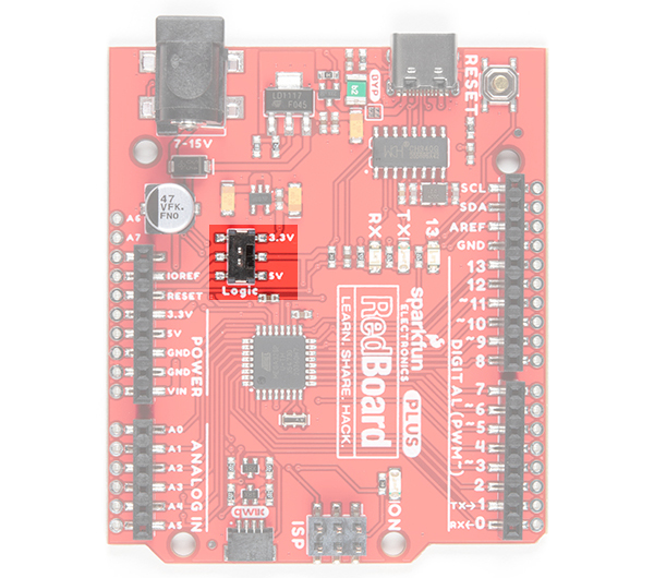
I/O Logic Level Switch
For more advanced users, we've added an I/O voltage switch also known as the "Red Squirrel" switch (because they are the one who petitioned for the mod). Now you can easily select the GPIO voltage between 3.3V or 5V with just your finger. This is extremely handy if you have a shield or 3.3V sensitive devices, such as an SPI interface, that needs protecting. Worried about accidentally flipping the switch? A piece of tape will lock it in place!
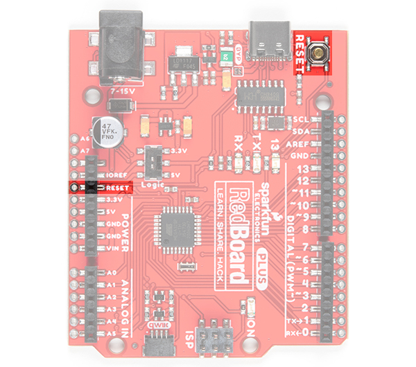
Reset
Pushing the reset button will temporarily connect the reset pin to ground and restart any code that is loaded on the Arduino. This can be very useful if your code doesn’t repeat, but you want to test it multiple times. You can also use a jumper wire to connect the RESET pin to ground as another option. Certain shields may utilize this pin and reroute it to the top of the shield as well.
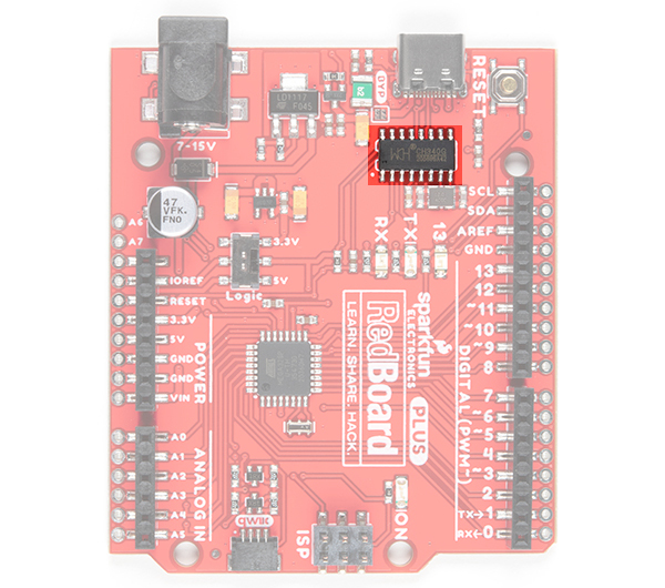
CH340C USB-to-Serial Converter
Unlike the classic RedBoard, that uses an FTDI IC; this board uses the CH340C IC for USB-to-serial conversion. One advantage is that it does not need a driver since most operating systems will have the drivers already installed. The chip is used to convert USB data coming to and from your computer into a serial protocol for the microcontroller.
- Whenever you upload to your board or send serial data, you should seen the RX and/or TX LEDs flashing. The best way to test the functionality of this part is to send serial data between your computer and the board.
- For more details on what happens in the Arduino IDE when code is uploaded through the bootloader, check out this great forum post.
For more tips and details on serial communication, read our Serial Communication and Terminal Basics tutorials. There are also good examples of using the serial communication with Arduino in the SparkFun Inventor's Kit v4.1.
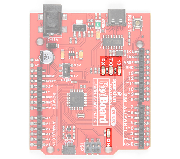
Status LEDs
There are 4 status LEDs on the RedBoard Plus.
- ON - The first LED is the power LED. This LED indicates that there is a potential between the VCC and GND pins. A good secondary test for this status indicator is to use a multimeter to test the VIN, 5V, and 3.3V pins against the GND pin.
- RX/TX - The next two status LEDs are the serial communication LEDs. These LEDs indicate that there is data moving between the serial UART RX/TX pins and the USB-to-Serial Converter. A good secondary test for this status indicator is to make sure that these LEDs are flashing during upload or any other serial communication.
- 13 - The last indicator is the pin 13 LED. This is typically only used as a test LED to make sure that a board is working or for basic debugging. However, for the RedBoard Plus, this LED can also indicate if there is presence of the bootloader. Usually the board is flashed with the bootloader . If the board was properly flashed, the LED should blink when powered up.
- New boards will come programmed with a test sketch that cycles between the RX and TX LEDs.
- Pin 13 is difficult to use as a digital input because of the voltage drop from status LED and resistor soldered in series to it. If the pin is enabled as an input with the internal 20k pullup resistor, it will always read a LOW state; an expected 5V (HIGH) signal will instead read around 1.7V (LOW).
If you must use pin 13 as a digital input, it is recommended that you set the pinMode() as an INPUT and use an external pulldown resistor.
pinMode(13, INPUT);
Microcontroller
The microcontroller (ATmega328P IC) is the work horse of the RedBoard Plus. The ATmega328 is an 8-bit AVR microcontroller manufactured by Atmel, now Microchip. Once an Arduino sketch is uploaded to the board, the program is stored in the memory of the ATmega328. The microcontroller will then run/execute the program while the RedBoard Plus is powered.
Clock
An external 16MHz crystal is used as the clock for the ATmega328P. When setting the system voltage to 3.3V using the I/O logic level switch, technically you will be overclocking the ATmega328P. We've done this on other designs and have not seen any issues so your mileage may vary. If this is a concern, we recommend setting the system voltage to 5V.
Memory
The ATmega328 has Flash, SRAM (Static Random Access Memory), and EEPROM (Electrically Erasable Programmable Read-Only Memory) memory.
- 32KB Flash Memory - where the Arduino sketch/program is stored (including the 512 byte Optiboot bootloader).
- 2KB SRAM - where the sketch/program creates and manipulates variables when it runs.
- 1KB EEPROM - is available for stable long-term storage (read/written with the EEPROM library).
The Flash and EEPROM memory are non-volatile; the data is still stored even when the board is no longer powered. The SRAM, on the other hand, is volatile and the data is only available while the board is powered.
- The EEPROM can be corrupted with low power/brown out issues.
- When you run out of SRAM, the sketch may fail or act strangely after it is uploaded. If you suspect this is the issue, try to comment out any long strings or large data structures. If the sketch starts to run normally, then you may need to modify your data requirements.
Bootloader
The Optiboot bootloader is a unique piece of firmware (512 bytes) at the end of the address space of the flash memory. The Optiboot bootloader is specifically configured for the ATmega328P to interface with the Arduino IDE, through a serial interface, to upload code. Without a bootloader, you would need an external programmer and program the microcontroller through the SPI interface (specifically, the ISP/ICSP headers).
For more details on the ATmega328, memory, and the bootloader check out these tutorials:
- Arduino Memory Tutorial
- SparkFun EEPROM Tutorial
- Arduino Bootloader Page
- Arduino as ISP and Arduino Bootloaders
- StackExchange Forum Post on Bootloaders
You can also find the datasheet for the ATmega328 from the Microchip product page.
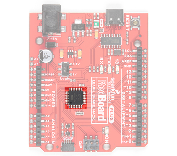
Microcontroller I/O Pins
All of the I/O pins on this board are digital inputs or outputs for the microcontroller (ATmega328P). There are select pins, like the Analog pins, which have additional capabilities.
Digital I/O
There are 22x I/O pins on this board that can be used as digital inputs or outputs for the microcontroller (ATmega328P). This includes the pins labeled as Analog, which may be configured and used in the same manner as the Digital pins. These are what you connect to buttons, LEDs, sensors, etc. to interface the Arduino with other pieces of hardware.
Input
By default, all digital I/O pins are configured as inputs. It is best practice to define the pinMode() in the setup of each sketch (programs written in the Arduino IDE) for the pins used. When configured properly, an input pin will be looking for a HIGH or LOW state. Input pins are High Impedance and takes very little current to move the input pin from one state to another.
- If an input pin is read and that is floating (with nothing connected to it), you will see random data/states. In practice, it may be useful to tie an input pin to a known state with a pullup resistor (to VCC), or a pulldown resistor (to GND).
- There are 20K pullup resistors built into the ATmega328 chip that can be configured by setting the pinMode() as INPUT_PULLUP.
- Pin 13 is difficult to use as a digital input because of the voltage drop from status LED and resistor soldered in series to it. If the pin is enabled as an input with the internal 20k pullup resistor, it will always read a LOW state; an expected 5V (HIGH) signal will instead read around 1.7V (LOW). If you must use pin 13 as a digital input, it is recommended that you set the pinMode() as an INPUT and use an external pulldown resistor.
Output
When configured as an output the pin will be at a HIGH or LOW voltage. Output pins are Low Impedance: This means that they can provide a substantial amount of current to other circuits.
Additional Functions
There are several pins that have special functionality in addition to general digital I/O. These pins and their additional functions are listed in the tabs below. For more technical specifications on the I/O pins, you can refer to the ATmega328P datasheet.
Analog Input Pins
There are 6x analog inputs on the analog header and 2x additional analog pins next to the power header. These pins all have 10-bit (10-bit = 1024 different values) analog to digital converter (ADC), which can be used to read in an analog voltage between 0 and VCC. These are useful if you need to read the output of a potentiometer or other analog sensors.
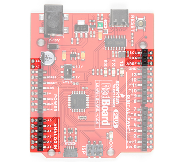
Analog pins 4 and 5 also support I2C (TWI) communication using the Wire library.
For more details on the analog inputs, check out these tutorials:
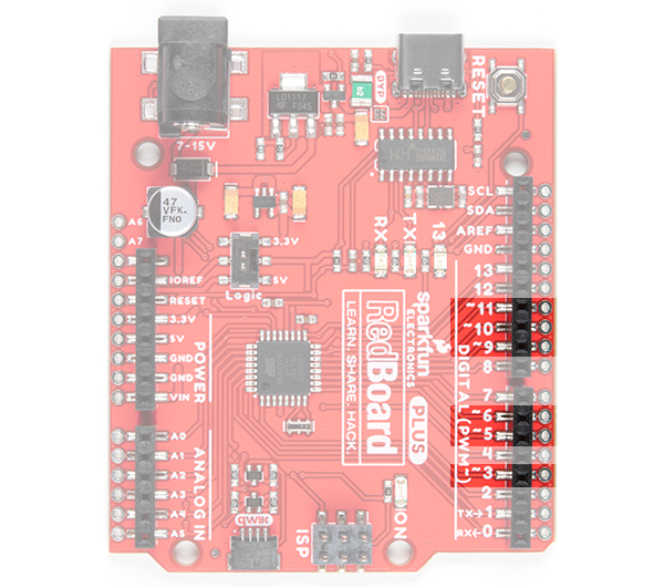
Pulse Width Modulation (PWM) Output Pins
Digital pins (3, 5, 6, 9, 10, and 11) marked with a tilde (~) are 8-bit PWM capable outputs, which you can use to dim LEDs or run servo motors.
For more details on pulse width modulation, check out these tutorials:
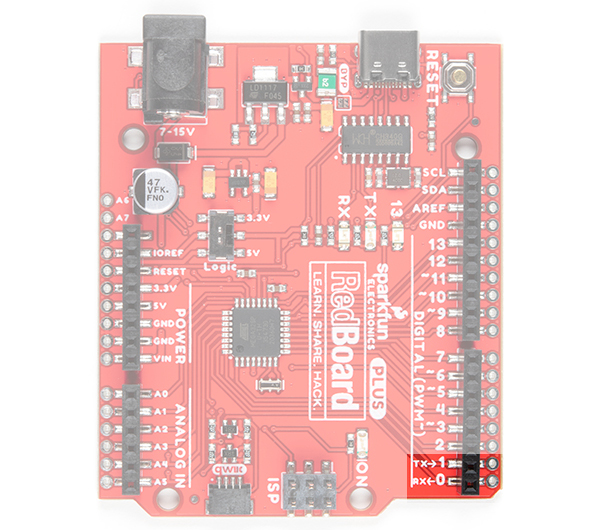
Serial Communication Pins
Digital pins 0 (RX) and 1 (TX) are also dedicated serial communication pins ties to the USB-to-serial converter (CH340C). These pins are used to receive (RX) and transmit (TX) TTL serial data as well as program the microcontroller. Other digital pins can be use to emulate serial communication with SoftwareSerial().
For more details on serial communication, check out these tutorials:
- SparkFun Serial Communication Tutorial
- Arduino Serial Reference Page
- Arduino SoftwareSerial Reference Page
- Arduino SoftwareSerial Tutorial
SPI Communication Pins
Digital pins 10 (CS), 11 (COPI), 12 (CIPO), and 13 (SCK) support Serial Peripheral Interface (SPI) communication.
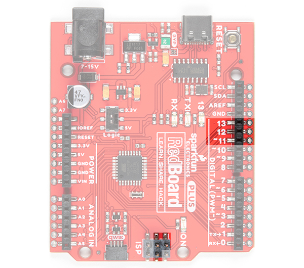
Executing "
SPI.end();" allows those pins 11 and 13 to be used as general I/O again.
For more details on the serial peripheral interface, check out these tutorials:
- SparkFun SPI Tutorial
- Arduino SPI Tutorial
- Arduino SPI Reference Page
- Arduino SPI Settings Reference Page
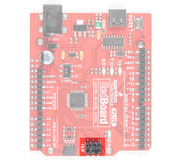
ISP or ICSP Connector
A less common way for most users to program the microcontroller on their board, is to use the ISP header. This method programs a microcontroller directly through the SPI pins. A more experienced user, with a firm grasp on digital electronics and the microcontroller (datasheet), will probably use a software package like Atmel studio, which is easier to debug.
The most common reasons for programming an AVR via an in-system programmer (ISP) are:
- ISP is faster and more reliable - We use this method in our QC process for most boards.
- There is no bootloader on the microcontroller or your board wasn't flashed properly:
- This is probably the only way to program the microcontroller without a bootloader.
- You want to use your own, custom bootloader.
- Configure fuse bits for various settings.
- Program without bootloader, when you need just a little bit more space for your program to load.
Most AVRs are programmed through a Serial Peripheral Interface (SPI). There are six unique signals required for communication between ISP and AVR.
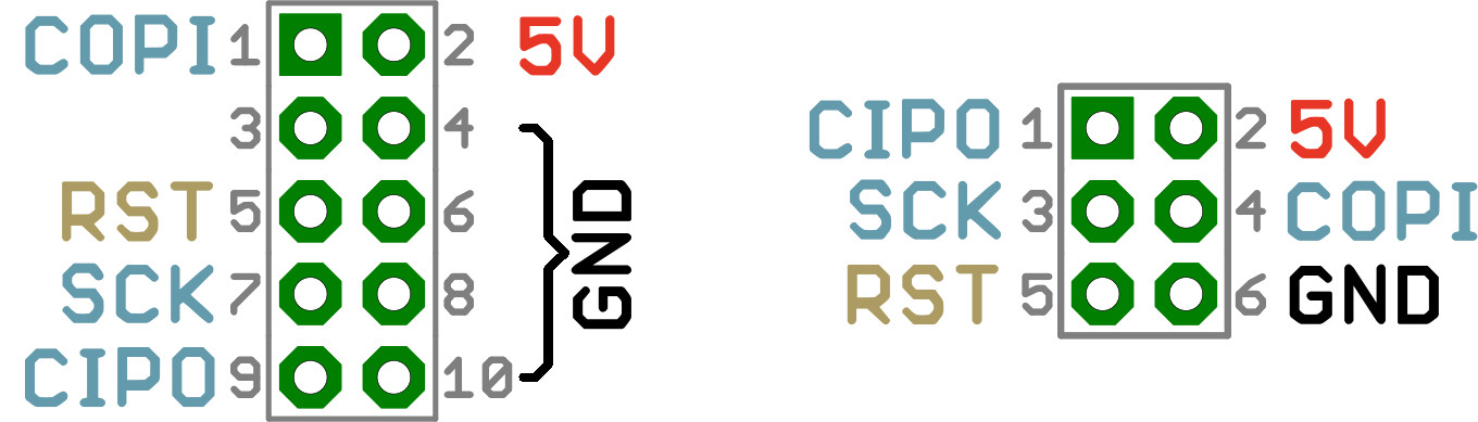
On the RedBoard Plus the COPI and D11 pins, CIPO and D12 pins, and SCK and D13 pins are tied together. To program the RedBoard Plus through the ISP pins, you will want to set the I/O jumper to 5V. This will tie the VCC of the microcontroller to the 5V rail//pin of the ISP header. Otherwise, you will probably run into issues and likely damage the I/O pins and/or the microcontoller chipset.
Often, this method is used as a last ditch effort, when after all else has failed to revive a board (do not attempt, unless you know what you are doing). Most likely your board isn’t bricked unless you have done something drastic like modified the fuses. In which case, reflashing the board probably won’t help you. However, if you have no options left and want to try to reflash the bootloader with an Uno or RedBoard. Here are links to some tutorials to get you started:
- SparkFun's Installing an Arduino Bootloader Tutorial
- Arduino as ISP and Arduino Bootloaders
- Arduino Programming a Microcontroller Tutorial
- Pi AVR Programmer Hookup Guide
Back then, it wasn't as easy to get into programming or processing. Without a USB-to Serial Converter or Bootloader, you needed an external ISP programmer to flash a microcontroller. You needed to use a lower level language and complex development platform to create and compile code for your microcontroller. Before flash memory, you could only program chips once.
I2C Communication Pins
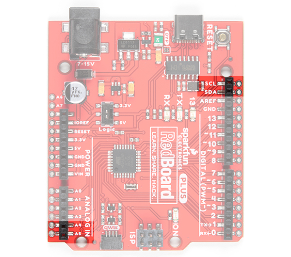
Analog pins 4 (SDA) and 5 (SCL) support I2C (TWI) communication. These are connected to a few locations.
Be sure to double check that you are not trying to use and I2C device while you are trying use analog pin 4 or 5 to read analog data, you will run into issues. You can only do one or the other.
For more details on the serial peripheral interface, check out these tutorials:
I2C and Qwiic
The most convenient feature of the board is the Qwiic connector that allows the RedBoard Plus to seamlessly interface I2C devices with the SparkFun's Qwiic Ecosystem. Simply connect a Qwiic cable between your Qwiic enabled device and the RedBoard Plus's Qwiic connector and you are good to go! There are logic level converters by the Qwiic connector to safely convert the logic levels to 3.3V if the logic switch is on the 5V side. These I2C pins are connected to A4 and A5.
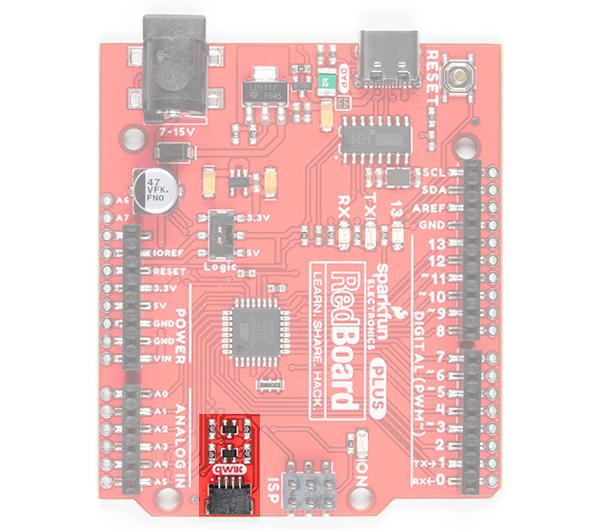
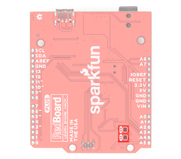
Analog Input (A4/A5) Jumpers
The back of the board includes jumpers on the back of the board in case you need to disconnect the logic level converters from A4/SDA and A5/SCL pins. This is if you need to use the pins to take analog readings. To modify, you will need a hobby knife to modify the A4/A5 jumpers. To modify the jumper, located on the back of the board next to the analog pins, you need to cut the trace between the two pads. Once you have cut the trace, the Qwiic connector and logic level conveters will be disconnected. To repair the connection, you just need to solder a jumper between the pads of both jumpers. Be sure to test the jumper with a multimeter to make sure you have a good soldered connection.
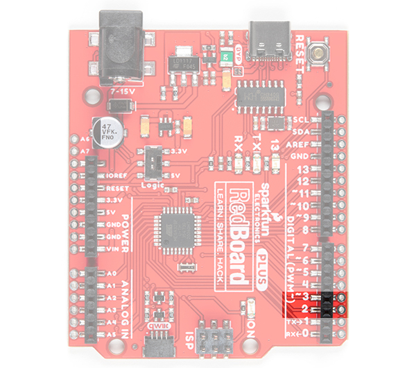
Interrupt Pins
Interrupts allow you to interrupt the code running in your main loop and execute another set of instructions (also known as interrupt handler or interrupt service routine) before returning back to the main loop. Digital pins 2 and 3 can be configured to trigger an interrupt on a low value, a rising or falling edge, or a change in value.
For more details on the interrupts, check out these tutorials:
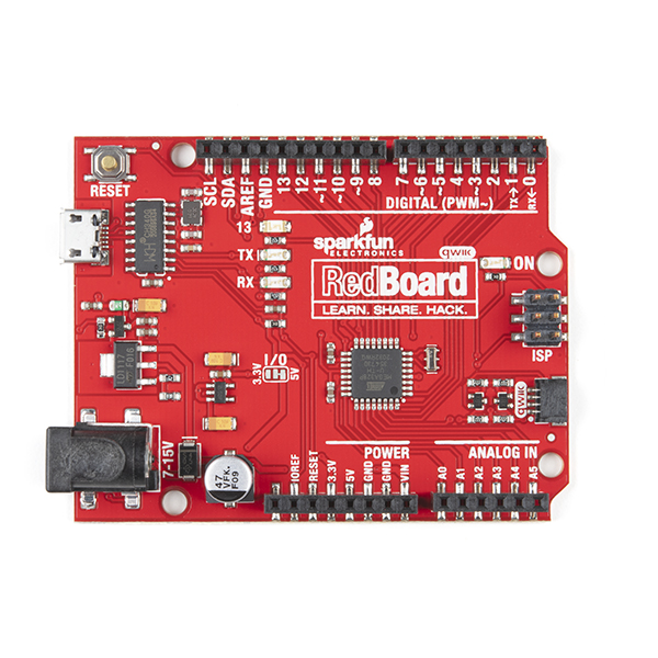
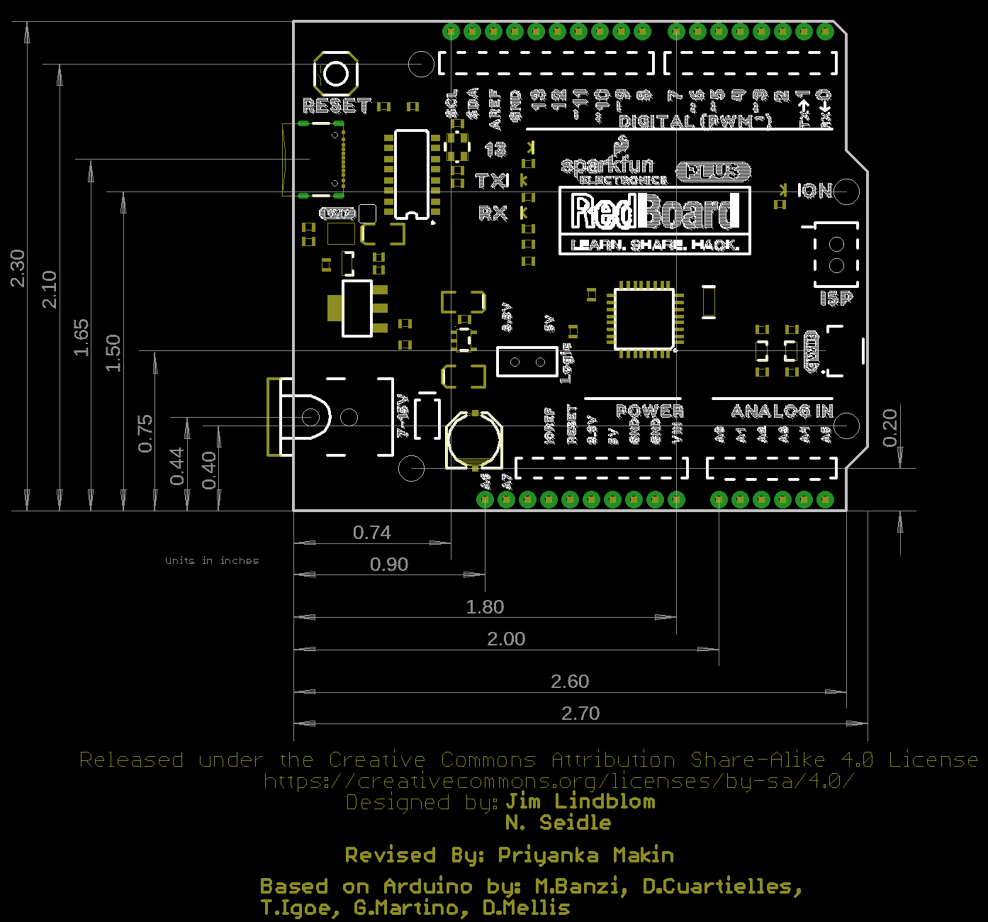
Board Dimensions
The board dimension is approximately 2.7" x 2.3". The board includes four mounting holes and female headers laid out in a standard Arduino Uno R3 footprint for Arduino shields. For the more details on the board sizing and component placement please refer to the Eagle files provided.
Hardware Assembly
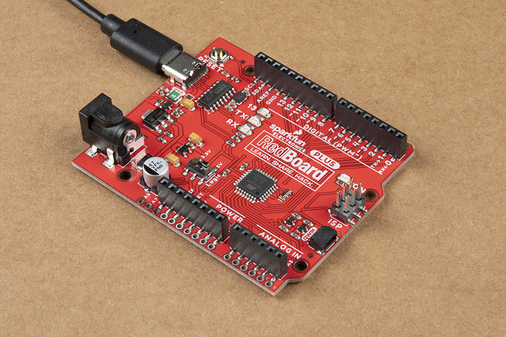
To power and program the board, all you need is a USB C cable. Hold down on the connector with your index finger and thumb on one hand. Using your other hand's index finger and thumb, insert the USB cable into the connector.
At a minimum, your board should look like the image below.
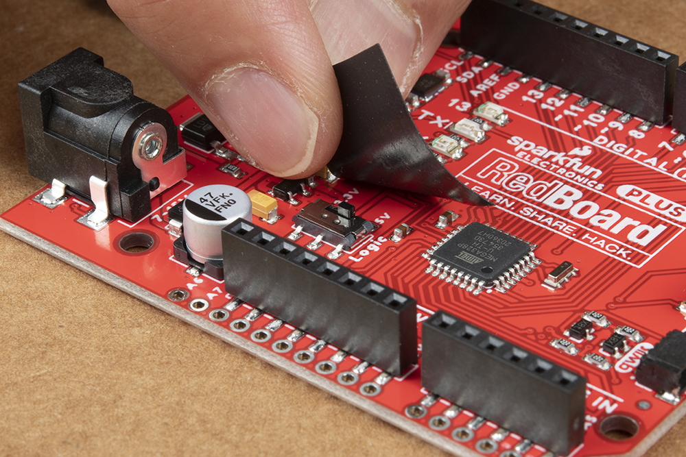
I/O Logic Level Voltage
We recommend having the board set to 5V for the system voltage. Once set, we recommend adding a piece of tape to hold the switch down to avoid accidentally damaging any 3.3V sensitive devices connected to the board or any peripherals expecting 5V logic when prototyping.
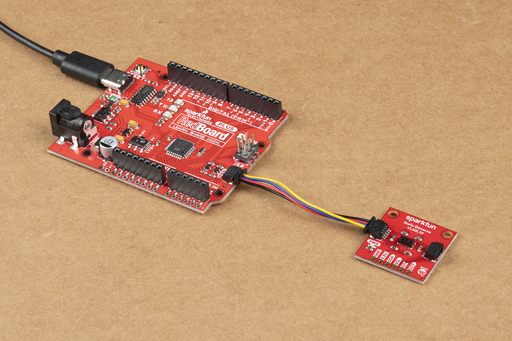
Qwiic Device
If you decide to connect a Qwiic-enabled device to the board, simply plug in a Qwiic cable between the RedBoard Plus and your chosen Qwiic device. The Qwiic connect system makes it easy to add additional functionality to the board. If you're going to be soldering to the through hole pins for I2C functionality, then just attach lines to power, ground, and the I2C data lines on the header pins or PTH pads.
3.3V Power Injection
The 3.3V voltage regulator should provide sufficient power to your Qwiic enabled devices. In special cases, you may need to disconnect the 3.3V line and inject a separate 3.3V regulated voltage down the line if you have several daisy chained Qwiic devices. You can leave the GND line alone, as that ground loops your system, providing a consistent reference voltage for your I2C signals.
By cutting the 3.3V line, this allows you to power all your devices without straining the 3.3V regulator on the board. Since, all voltage regulators are slightly different and don't maintain a perfect 3.3 voltage, the 3.3V AP2112 regulator would be constantly battling the voltage regulator of your separate power supply to regulate its version of 3.3V. For more details on voltage regulators, check out this According to Pete blog post. Or check out the How to Power a Project: Voltage/Current Considerations for some ideas on adding power to your daisy chained Qwiic devices.
Jumper Wire
All of the pins are broken out to 0.1"-spaced female headers (i.e. connectors) on the outer edges of the board. Additionally, there are PTH pads adjacent to each pin. There are a variety of wires, connectors, and other items that can be inserted into these headers to interface with the Arduino. Jumper wires are a good option if you want to connect the RedBoard Plus up to other pieces of circuitry that may live on a breadboard. Below is an example circuit taken from the SparkFun Inventor's Kit V4.1.
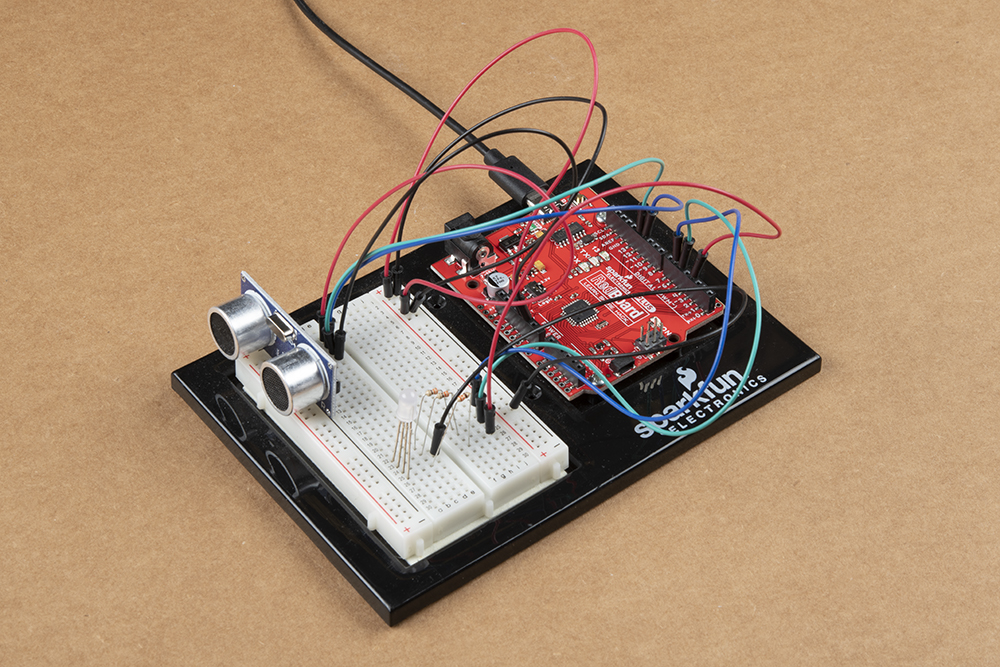
When connecting to the headers, be sure you are aware of the functionality of the pins you are using.
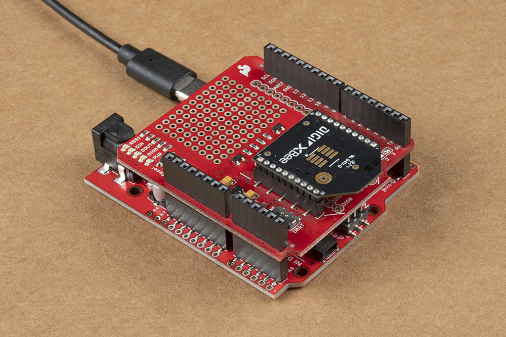
Arduino Shields
Shields are another popular way to interface with the headers. These Arduino-shaped boards are stackable and connect to all four headers of the RedBoard Plus at once. Shields exist in hundreds of forms, they can add GPS, WiFi, MP3 decoding, and all sorts of other functionality to your Arduino. For more details on Arduino shields and shield assembly, please refer to this Arduino Shields tutorial.
Installing Drivers
The RedBoard Plus uses a CH340G USB-to-Serial adapter made by WCH. The driver for the CH340G chip will need to be installed on your computer. We have tested and confirmed that the driver works on Windows 7, Windows 10, Mac OSX High Sierra, and Raspbian Stretch (11-13-2018 release) for the Raspberry Pi. On all operating systems, if you have previously installed the CH340G drivers, you will need to uninstall those drivers first before updating to the new CH340G driver. For more information, check out our How to Install CH340 Drivers Tutorial.
How to Install CH340 Drivers
Installing the CH340G driver allows your computer to recognize the RedBoard Plus as a device and lets it communicate with the board over the USB connection. You can also find the latest version of the CH340 drivers from WCH here. (Most of their pages are in Mandarin, but if you use a Chrome web browser, you should have the option to have the web page translated.)
Installing the Arduino IDE
Download/Install Arduino
You can download the Arduino IDE from their website. They have installation instructions, but we will also go over the installation process as well. Make sure you download the version that matches your operating system.
The installation procedure is fairly straightforward, but it does vary by OS. Here are some tips to help you along. We've also written a separate Installing Arduino tutorial in case you get stuck.
- We recommend using a computer with a full desktop operating system like Windows 7/10 (avoid Windows 8 if you can), Mac OSX, and certain flavors Linux (check the Arduino FAQ page for compatibility).
- If you are not a technical or computer savy individual and you have your choice of computers, I highly recommend using a Windows 7 or 10 computer. You will usually run into the the least issues, if any, with these operating systems.
- We do NOT recommend using a Chromebook, Netbook, tablet, phone, or the Arduino Web IDE in general. You will be responsible for troubleshooting any driver or Arduino Web IDE issues.
- As of writing this tutorial (12-14-2018), the most recent and stable release of the Arduino IDE is version 1.8.5. We recommend using that version of the Arduino IDE; you can download the previous releases here.
- On Windows 10, we do NOT recommend installing the Arduino IDE from the app store. You may run into issues because the OS will automatically update to the most recent release of the Arduino IDE, which may have unknown bugs (like the compiler errors in versions 1.8.6 and 1.8.7).
- Raspberry Pi users with Raspbian installed should use the Linux ARM download. We do not recommend using the command line installation. It will install the oldest release of Arduino, which is useless when it comes to installing new boards definitions or libraries.
- For additional troubleshooting tips, here is a troubleshooting guide from Arduino.
Windows Install Tips
The Windows version of Arduino is offered in two options: an installer or a zip file. The installer is the easier of the two options, just download that, and run the executable file to begin the installation.
Windows install steps. Click the image to get a bigger view.
When you're prompted to install a driver during installation, select "Install". This will install drivers for Arduino specific boards (like the Uno, Nano, etc.) that you may use in the future.
- If you choose to download the zip file version of Arduino, you'll need to extract the files yourself. Don't forget which folder you extract the files into! You will need to run the executable Arduino file in the folder to start the Arduino IDE.
- On Windows 10, there is an option to install Arduino through their app store. we do not recommend installing the Arduino IDE from the app store. You may run into issues because the OS will automatically update to the most recent release of the Arduino IDE, which may have unknown bugs.
Mac Install Tips
The Mac download of Arduino is only offered in a zip file version. After the download is finished, simply double-click the .zip file to unzip it.
Mac OSX Arduino.app
Following that, you'll need to copy the Arduino application into your applications folder to complete the installation.
Linux Install Tips
As Linux users are no doubt aware, there are many flavors of Linux out there, each with unique installation routines. Check out the FAQ section of the Arduino webpage for more details. Otherwise, you can also use the Linux section of our Installing Arduino tutorial for some helpful links for an assortment of Linux distributions.Raspbian Stretch
Raspberry Pi users with Raspbian installed should use the Linux ARM download. Do not use the command line installation process. For more information, please refer to this blog post from Arduino.Ubuntu and Debian
For Ubuntu and Debian users, installing Arduino should only need a simple "apt-get" command like:sudo apt-get update && sudo apt-get install arduino arduino-core
Other Distributions
Other Linux distros aren't too dissimilar from the Ubuntu and Debian instructions.
With Arduino downloaded and installed, the next step is to plug the board in and test it out! Pretty soon you'll be blinking LEDs, reading buttons, and doing some physical computing!
Arduino Examples
Example 1: Uploading Blink
In this example we will go over the basics of the Arduino IDE and upload a sample code. This is a great way to test the basic functionality of any board to make sure it is working.The Arduino IDE
Now it's finally time to open up the Arduino software. You'll be presented with a window that looks a little something like this: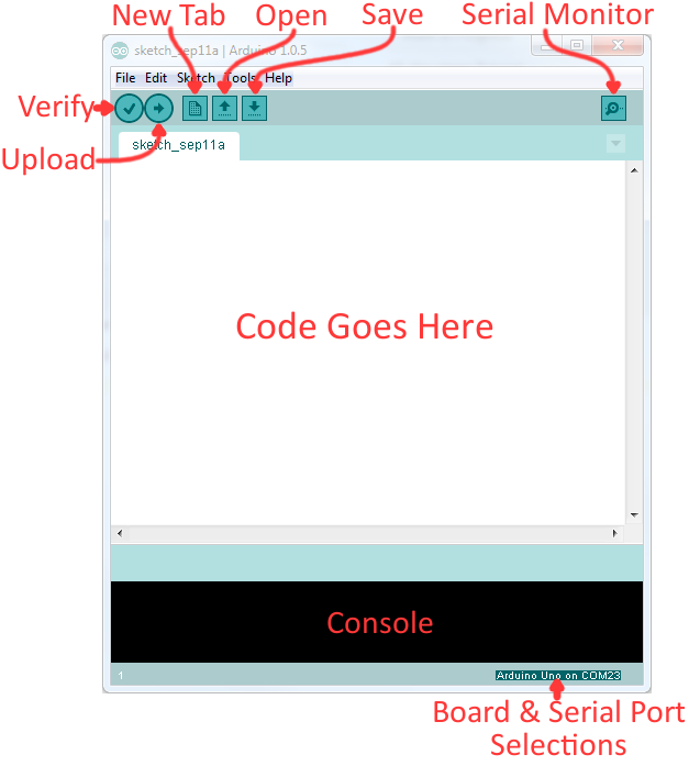
Layout of the Arduino IDE.
Before we can send the code over to the RedBoard, there are a couple of adjustments we need to make.
Select a Board
This step is required to tell the Arduino IDE which of the available Arduino boards, we are using. Go up to the Tools menu. Then hover over Board and make sure Arduino/Genuino Uno is selected.
Screen shot of Board selection.
Select a Serial Port
Next up we need to tell the Arduino IDE which of our computer's serial ports the RedBoard is connected to. For this, again go up to Tools, then hover over Serial Port and select your RedBoard's COM port.
Screen shot of COM Port selection.
If you've got more than one port, and you're not sure which of the serial ports is your RedBoard, unplug it for a moment and check the menu to see which one disappears.
Blink Sketch
Code written for the Arduino IDE are referred to as sketches. All code in Arduino is C based. Let us upload a Blink sketch to make sure our new RedBoard setup is totally functional. Go up to the File menu in Arduino, then go to Examples > 01.Basics > Blink to open it up.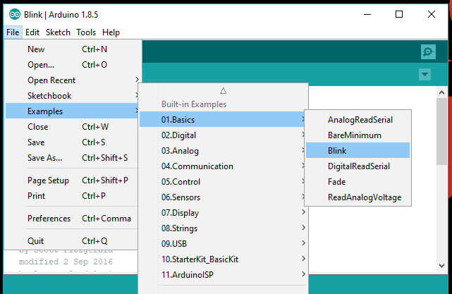
Screen shot of Blink sketch selection.
Upload!
With all of those settings adjusted, you're finally ready to upload some code! Click the Upload button (the right-pointing arrow) and allow the IDE some time to compile and upload your code. It should take around 10-20 seconds for the process to complete. When the code has uploaded, you should see something like this in your console window: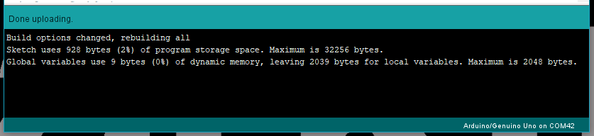
Screen shot of upload complete.
And if you look over to the RedBoard, you should see the blue LED turn on for a second, off for a second, on for a second, off for a second...ad infinitum (at least until it loses power).
If you want to adjust the blink speed, try messing with the "1000" value in the delay(1000); lines. You're well on your way to becoming an Arduino programmer!
Something Wrong?
Uh oh! If you didn't get a "Done Uploading" message, and instead got an error, there are a few things we can double-check.If you got an avrdude: stk500_getsync(): not in sync: resp=0x00 error in your console window.
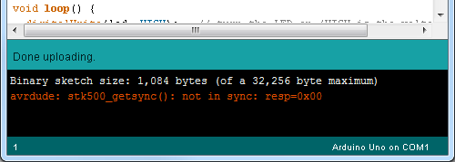
Screen shot of Error Message in the Console.
Either your serial port or board may be incorrectly set. Again, make sure Arduino/Genuino Uno is the board selection (under the "Tools > Board" menu). The serial port is usually the more common culprit here. Is the Serial Port correctly set (under the "Tools > Serial Port" menu)? Did the drivers successfully install? To double check your RedBoard's serial port, look at the menu when the board is plugged in, then unplug it and look for the missing port. If none of the ports are missing, you may need to go back to driver installation.
Example 2: Qwiic Connector
One of the great features of the RedBoard (Qwiic) is its ability to interface with I2C devices using our Qwiic system. The Qwiic system is a solderless connection system that allows users to seamlessly daisy chain multiple I2C devices with ease.The Qwiic Distance Sensor
For this example, we will be running a basic sketch using the SparkFun 4m Distance Sensor (VL53L1X). For more examples with this sensor, please refer to the complete hookup guide.Hardware Assembly
The wiring for this is simple. Use the Qwiic cable and connect the distance sensor to the board. That is it! The connections are polarized, so you don't have to worry about which side or connector you are using. Let's run an example for our distance sensor to see how it behaves.
Install the Arduino Library
Note: If you have not previously installed an Arduino library, please check out our Arduino library installation guide.
First, you'll need the Sparkfun VL53L1X Arduino library. You can obtain these libraries through the Arduino Library Manager. Search for Sparkfun VL53L1X Arduino Library to install the latest version. If you prefer downloading the libraries from the GitHub repository and manually installing it, you can grab them here:
Example 1 - Read Distance
To get started with this example, open up File > Examples > SparkFun VL53L1x 4M Laser Distance Sensor > Example1_ReadDistance. In this example, we begin by creating aSFEVL53L1X object called distanceSensor with our wire port, Wire, and then our shutdown and interrupt pins. Then we initialize our sensor object in the setup() loop. The code to do this is shown below.
language:c
#include <Wire.h>
#include "SparkFun_VL53L1X.h"

//Optional interrupt and shutdown pins.
#define SHUTDOWN_PIN 2
#define INTERRUPT_PIN 3

SFEVL53L1X distanceSensor(Wire, SHUTDOWN_PIN, INTERRUPT_PIN);

void setup(void)
{
  Wire.begin();

  Serial.begin(9600);
  Serial.println("VL53L1X Qwiic Test");

  if (distanceSensor.init() == false)
    Serial.println("Sensor online!");

}
Once we've initialized our sensor, we can start grabbing measurements from it. To do this, we send some configuration bytes to our sensor using distanceSensor.startRanging() to initiate the measurement. We then wait for data to become available and when it does, we read it in, convert it from millimeters to feet, and print it out over serial. The void loop() function that does this is shown below.
language:c
void loop(void)
{
  distanceSensor.startRanging(); //Write configuration bytes to initiate measurement
  int distance = distanceSensor.getDistance(); //Get the result of the measurement from the sensor
  distanceSensor.stopRanging();

  Serial.print("Distance(mm): ");
  Serial.print(distance);

  float distanceInches = distance * 0.0393701;
  float distanceFeet = distanceInches / 12.0;

  Serial.print("\tDistance(ft): ");
  Serial.print(distanceFeet, 2);

  Serial.println();
}
Opening your serial monitor to a baud rate of 9600 should show the distance between the sensor and the object it's pointed at in both millimeters and feet. The output should look something like the below image.
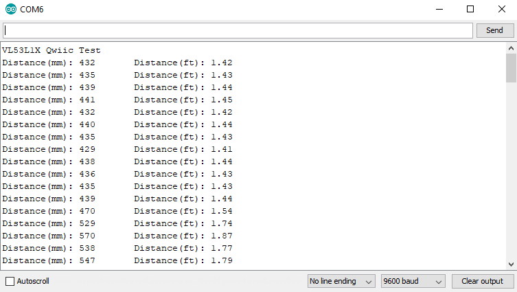
Distance readings in mm and ft
Troubleshooting
Below, we have also included some additional troubleshooting tips for issues that you may come across with the new RedBoard Plus.
- One of our employees compiled a great list of troubleshooting tips based on the most common customer issues. This is the perfect place to start.
- For any Arduino IDE specific issues, I recommend starting with their troubleshooting guide.
If neither of the troubleshooting guides above were able to help, here are some tips you might have missed. (Most of this material is summarized from the tutorial.):
Are You Using a Recommended Computer OS?
This board is not tested using the Arduino Web IDE. We do NOT recommend using a Chromebook, Netbook, tablet, phone, or the Arduino Web IDE in general. If you are here, try a RECOMMENDED operating system (see Installing the Arduino IDE).My Board Isn't Working:
Every board that we manufacture gets tested. If you didn't buy the board from us or one of our authorized distributors, it could be a knock-off. That being said, let's try a basic test to see if just the board is working. Disconnect everything that you have attached to the board; we just want to test the board.- Inspect the board:
Check the board to make sure everything looks about right. Use the pictures on the product page to verify component placement or alignment, and bad solder joints, or damage. - Power and check the status LEDs:
Using a known good USB C cable, plug your board in to the computer. Do any of the status LEDs turn on (see Hardware Overview)?- New boards will come programmed with a test sketch that cycles between the RX and TX LEDs.
- Upload the Blink sketch:
Try to upload a blink sketch. Why blink? It is simple, known to work (from the example files), and you have an indicator LED.- Double check that you have the proper Board and Serial Port selected.
- For boards that are already running the blink example, I recommend changing the timing parameters to check for a change in the board's response.
I Don't See My Board on a Serial/COM Port:
If you don't see your board as an available COM port on the Arduino IDE:- Try to re-open the Arduino IDE.
- Check the Device Manager to verify that your computer recognizes the board. Click the Driver Verification button in the Installing Drivers section of the tutorial.
- If you have previously installed the older CH340G drivers, you may need to update your drivers. Particularly on Macs, you will need to delete the previous drivers and install the updated drivers.
- If that is not the case, you issue might be related to your USB cable. Check that you are using a USB cable capable of data transfers. Some cables only have the power pins connected for charging. A good way to test this is to plug in a device to your USB cable (like a phone). If it doesn't show up as a device or drive, then try a new USB micro-B cable.
- This rarely happens, but it is easy to check. If you are using a USB 3.0 port (you will see a blue "tongue" in the USB jack or bad USB port, try a different USB port. You can also try to test the board on a different computer to double check for a hardware incompatibility (usually with expansion boards).
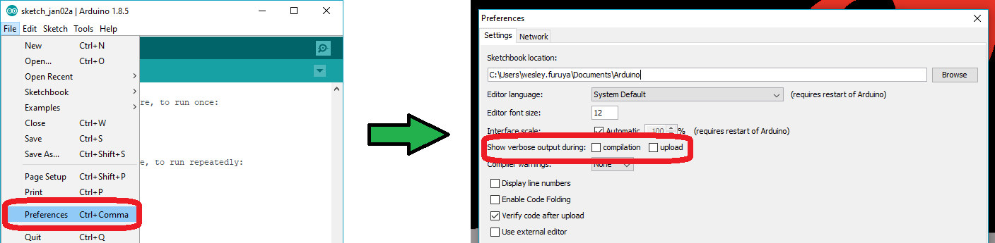
Errors Uploading to the Board:
There are two types of issues that you will usually see in the console of the Arduino IDE, compile errors or upload errors. The easiest way to see where to start is by clicking the Verify button (check mark); the Arduino IDE will try to compile your code. A failure here is a compile error.It takes a some experience, but if you enable the verbose output from the Arduino IDE preferences, it may give you more clues to where the issue is.
- Compile Errors:
With compile errors, there are several things that could be causing issues. However, 99% of the time, it is user error. Usually something wrong with your code or the library you are using. Once in a while you will have a file structure issue if you manually added a file/folder in any of the Arduino folders (still user error). - Upload Errors:
Upload errors get a little more tricky. You will usually just see the Arduino IDE trying to upload to the board multiple times. There are usually several different causes for this, often without specific errors in the console. Here are a few common examples:- Wrong Board Selection:
Double check you board selection options. If you uploaded with the wrong board selection, there is a small chance that you may have overwritten the bootloader on the board or damaged the microcontroller. - Missing Bootloader:
If your board has the bootloader flashed, pin 13 will flash several times on power up. - Serial Port Interference:
If a device is communicating to the microcontroller over digital pins 0 and 1, while you are trying to upload code. - Bad USB cable or port (see Serial Port section above).
- Wrong Board Selection:
Additional Tips:
If an input pin is read and that is floating (with nothing connected to it), you will see random data/states. In practice, it may be useful to tie an input pin to a known state with a pullup resistor (to VCC), or a pulldown resistor (to GND).
Pin 13 is difficult to use as a digital input because of the voltage drop from status LED and resistor soldered in series to it. If you must use pin 13 as a digital input, it is recommended that you set the pinMode() as an INPUT and use an external pulldown resistor.
The maximum current an I/O pin can source (provide positive current) or sink (provide negative current) is 40 mA (milliamps). You can power small sections of LED strips or small motors, but will run into issue with high power devices.
Be sure to double check that you are not trying to use an I2C device while you are trying use analog pins A4 or A5 to read analog data. You will run into issues where the analog read will appear to be at a constant value. As a result, the analog readings will not reflect the changes seen from the sensor output. You can only do one or the other.
Using the Serial Peripheral Interface, configures the SCK and MOSI pins to be directly managed by the SPI hardware. Therefore, while in use, pins 11 and 13 can't be used (i.e. the LED on pin 13 can no longer be used as a debug/status indicator.) Executing "SPI.end();" allows those pins 11 and 13 to be used as general I/O again.
This issue doesn't happen too often, but it can be arbitrarily, common: If your mouse pointer begins to move erratically, your mouse becomes unresponsive to your inputs, and your board is sending a lot of serial data, there is a chance that your computer thinks your board as a serial mouse. The fix is to unplug your board and the plug it back in while holding the reset button down, giving your computer a chance enumerate the COM port.
Resources and Going Further
Now that you've successfully got started with your RedBoard Plus, it's time to incorporate it into your own project! For more information, check out the resources below:
- Schematic (PDF)
- Eagle Files (ZIP)
- Board Dimensions (PNG)
- Graphical Datasheet (PDF)
- How to Install CH340 Drivers
- Qwiic Landing Page
- GitHub Hardware Repo
Need some inspiration for your next project? Check out some of these related tutorials:
SparkFun Tutorials
Installing an Arduino Library
What is an Arduino?
Installing Arduino IDE
Arduino Tutorials
Arduino Board Comparison Guides
Choosing an Arduino for Your Project
Standard Arduino Comparison Guide
RedBoard vs. Uno
Arduino Shields
Arduino Shields v2
Click the buttons above for tutorials relating to the board functionality based on topic difficulty.