Processor Interrupts with Arduino
 JordanDee, Ell C
 Introduction
Interrupts - what are they? They are people that intermittently prevent you from doing your current work. Ha! Well maybe... but what we really want to know is what they are in the context of embedded electronics and microprocessors.
So let's ask that again - what is an interrupt? In a nutshell, there is a method by which a processor can execute its normal program while continuously monitoring for some kind of event, or interrupt. There are two types of interrupts:
Hardware Interrupts - These occur in response to an external event, like a pin going high or low.
Software Interrupts - These occur in response to a software instruction.
Generally speaking, most 8-bit AVR microcontrollers (i.e. Arduinos) aren't innately capable of software interrupts, so for the purposes of this tutorial, we will focus on hardware interrupts.
Suggested Reading
If you aren’t familiar with the following concepts, we recommend checking out these tutorials before continuing.
What is an Arduino?
Installing Arduino IDE
How to Install FTDI Drivers
How Does It Work?
When the event or interrupt happens, the processor takes immediate notice, saves its execution state, runs a small chunk of code (often called the interrupt handler or interrupt service routine), and then returns back to whatever it was doing before.
The programmer defines the code that is to be executed when a particular interrupt occurs within the program itself. In Arduino, we use a function called attachInterrupt() to do this and the recommended syntax looks similar to the output below.
language:c
attachInterrupt(digitalPinToInterrupt(pin), ISR, mode)
This function takes three parameters:
First Parameter (i.e.
digitalPinToInterrupt(pin)) - Pin number of the interrupt, which tells the microprocessor which pin to monitor. The pin depends on the microcontroller being used.Second Parameter (i.e.
ISR) - The location of code we want to execute if this interrupt is triggered.Third Parameter (i.e.
mode) - Tells it what type of trigger to look for: a logic high, a logic low or a transition between the two.
For more information what pins are reserved for interrupts and some example code, check out Arduino's attachInterrupt() page.
Hardware Hookup
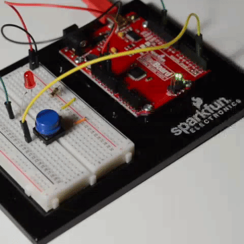
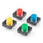
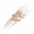
In the following sections, we'll look at a simple example to make more sense of interrupts and how they work. If you'd like to follow along, grab a Sparkfun RedBoard, an LED, a button, 330Ω resistor, jumper wires, and a cable to power it all.


Connect the LED to pin 13 and the button to pin 2 as you see in the Fritzing diagram below:
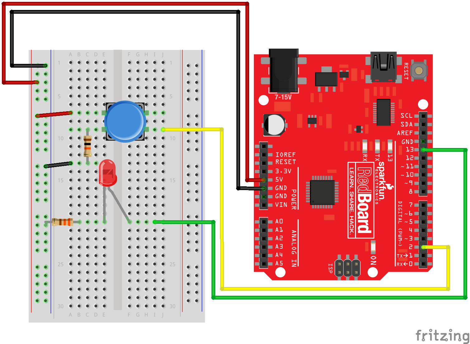
If you take a good look at what you've just hooked up, you'll notice that the LED is actually redundant. We could just use the built-in LED on pin 13, but for visual purposes, we added the external LED.
Example: Simple Interrupt
Now that we've got our hardware hooked up, let's look at a simple example that continuously sends an "Off" signal to an LED. We'll attach an interrupt to pin 2; this pin will monitor a button that will send an "On" signal to the LED when pressed and increment a counter.
Most Arduinos have 2 external interrupts built in: interrupt0 (on digital pin 2) and interrupt1 (on digital pin 3). Some boards have more (like the Arduino Mega 2560) - refer to the user manual or datasheet for more information on what your specific board supports. Arduino also has more details on a handful of boards on their attachInterrupt() page. Since we are using a RedBoard here, this example uses pin 2 to monitor for interrupts.
Simple Interrupt Example 1
Select the board and COM port for the RedBoard. Then upload the following.
   /*
    Simple Interrupt Example 1
    by: Jordan McConnell
    SparkFun Electronics
    created on 10/29/11
    */

    int ledPin = 13;  // LED is attached to digital pin 13
    int x = 0;  // variable to be updated by the interrupt

    void setup() {
      //enable interrupt 0 (pin 2) which is connected to a button
      //jump to the increment function on falling edge
      pinMode(ledPin, OUTPUT);
      attachInterrupt(0, increment, RISING);
      Serial.begin(9600);  //turn on serial communication
    }

    void loop() {
      digitalWrite(ledPin, LOW);
      delay(3000); //pretend to be doing something useful
      Serial.println(x, DEC); //print x to serial monitor
    }

    // Interrupt service routine for interrupt 0
    void increment() {
        x++;
        digitalWrite(ledPin, HIGH);
    }
The main loop of this program sends an "OFF" signal to the LED every 3 seconds. Meanwhile, this program watches digital pin 2 (which corresponds to interrupt 0) for a rising edge. In other words, it looks for a voltage change going from logic low (0V) to logic high (5V), which happens when the button is pressed. When this happens the function increment is called. The code within this function is executed, variable x is incremented, and the LED is turned on. Then the program returns to wherever it was in the main loop.
If you play around with it, you'll notice that the LED stays on for seemingly random amounts of time but never longer than 3 seconds. How long the LED stays on depends on where you interrupted the code in the main loop. For example, if the interrupt was triggered right in the exact middle of the delay function, the LED would remain lit for about 1.5 seconds after you hit the button.
Managing Bounce
One common problem with interrupts is they often can trigger multiple times for a single event. When you look at the serial output of the code in example 1, you'll notice that even if you press the button just once, x will increment many times. To explore why this happens, we have to take a look at the signal itself. If we took an oscilloscope to monitor the voltage of the pin at the moment we pressed the button, it would look something like this:
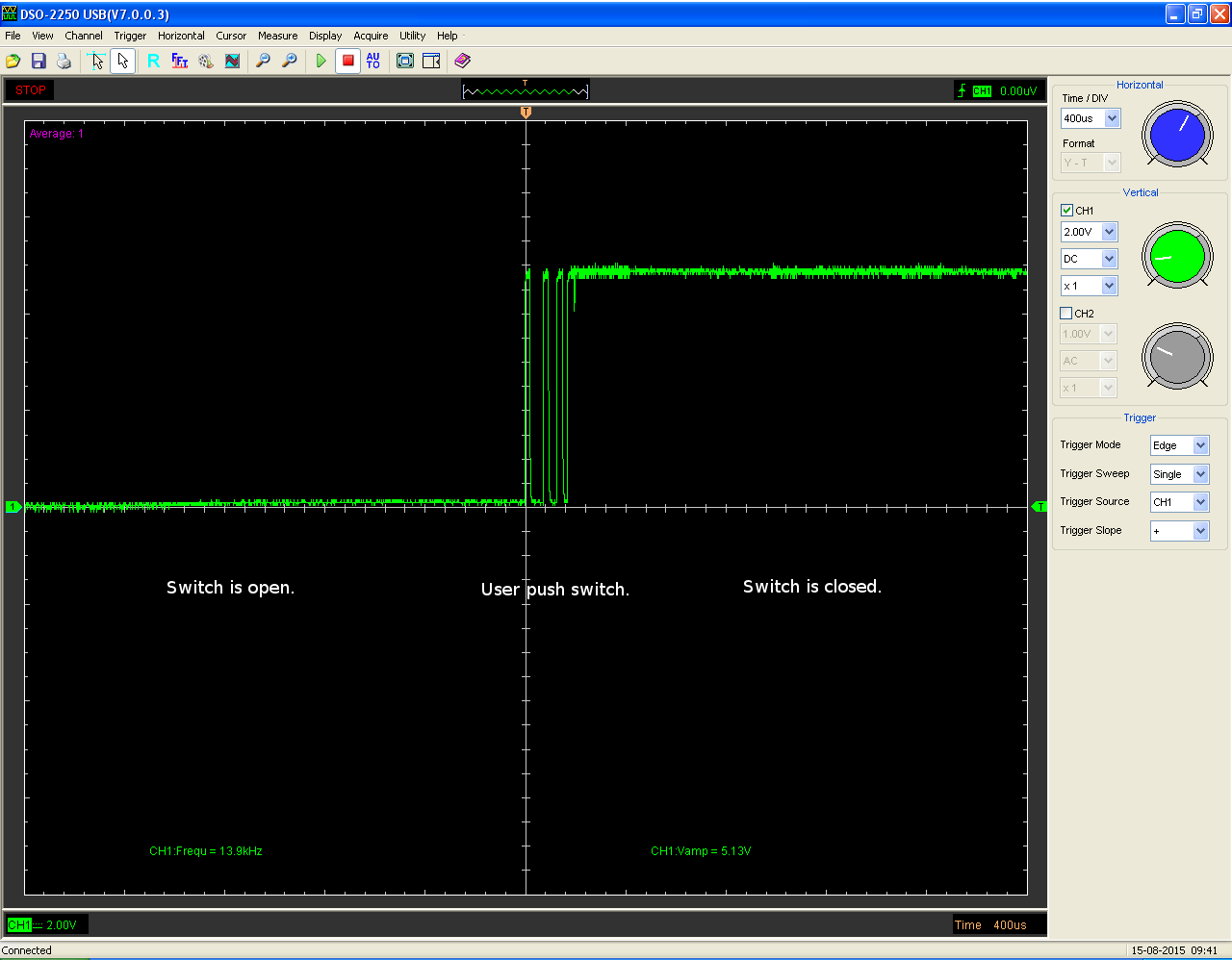
While the main transition of the pin is from low to high, during the process, there are several spikes which can cause multiple interrupts. This is referred to as noise or bounce. A button push might seem like a single step, but in reality the mechanical parts within that button come into contact multiple times before settling into a particular state. There are several ways to remedy this. Often you can fix bounce issues with hardware by adding an appropriate RC filter to smooth the transition. Another option is to address it in software by temporarily ignoring further interrupts for a small time frame after the first interrupt is triggered. Going back to our old example, let's add in a fix that allows the variable x to only be incremented once each button press instead of multiple times.
Simple Interrupt Example 2
Select the board and COM port for the RedBoard if you have not already. Then upload the following.
   /*
    Simple Interrupt example 2
    by: Jordan McConnell
    SparkFun Electronics
    created on 10/29/11
    */

    int ledPin = 13; // LED is attached to digital pin 13
    int x = 0; // variable to be updated by the interrupt

    //variables to keep track of the timing of recent interrupts
    unsigned long button_time = 0;
    unsigned long last_button_time = 0;

    void setup() {
      //enable interrupt 0 which uses pin 2
      //jump to the increment function on falling edge
      pinMode(ledPin, OUTPUT);
      attachInterrupt(0, increment, RISING);
      Serial.begin(9600);  //turn on serial communication
    }

    void loop() {
      digitalWrite(ledPin, LOW);
      delay(3000); //pretend to be doing something useful
      Serial.println(x, DEC); //print x to serial monitor
    }

    // Interrupt service routine for interrupt 0
    void increment() {
      button_time = millis();
      //check to see if increment() was called in the last 250 milliseconds
      if (button_time - last_button_time > 250)
      {
        x++;
        digitalWrite(ledPin, HIGH);
        last_button_time = button_time;
      }
    }
Let's look again at the serial output as you press the button. Open ther serial monitor set at 9600 baud. Note that increment only gets called once for each button press. This fix works because each time the interrupt handler is executed, it compares the current time retrieved by the millis() function with the time the handler was last called. If it's within a certain defined window of time, in this case a fourth of a second, the processor immediately goes back to what it was doing. If not, it executes the code within the if statement updating the variable x, turning on the LED and updating the last_button_time variable so the function has a new value to compare to when it's triggered in the future.
Interrupt Priority Levels
What happens when two interrupts occur at the same time? Most AVRs do not support what we call interrupt priority levels. Should two interrupts occur simultaneously or there are two or more interrupts waiting in a queue, the priority is determined by the order of their vector addresses. Lower vector addresses are serviced first, Reset will take precedence over all interrupt requests. Again, your datasheet will have more information on your specific board.
Example: Interrupting an LED Sequence
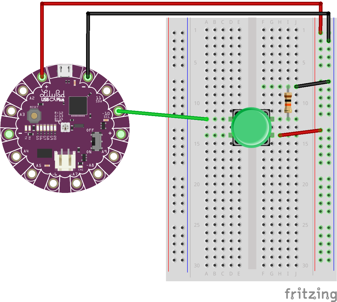
Interrupts can also come in handy when dealing with long sequences of things. Let's look at another simple example with LEDs - let's say that we are going to use the built-in RGB LED on a LilyPad USB Plus to cycle through a sequence of colors, fading each color on and off. The fade cycle time for each color is 10 seconds and we have a number of these boards sewn into costumes on stage. What happens if one of these costumes gets out of sync?
Rather than having to wait for the cycle to end and trying to reset the board in sync with the other boards, we can add an interrupt to pin 10 (this is interrupt 0 on the LilyPad USB Plus board). When the button is pressed, the interrupt is triggered and we move on to the next color. This allows us to get the offending costume in sync faster and the show can go on.
Let's make this happen for ourselves. If you'd like to follow along, grab a LilyPad USB Plus. You'll need the buttons, jumpers, and power supply from the previous experiment. You will also need a few alligator clip to pigtail wires to connect to the LilyPad sew tabs.
Hook it all up as you see here:
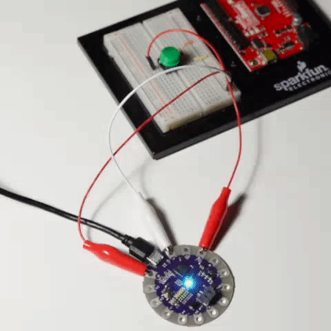
Select the board and COM port for the the LilyPad USB Plus. Then upload the code below.
/*
Example: Interrupting an LED sequence
SparkFun Electronics

Follow the tutorial at:
https://learn.sparkfun.com/tutorials/processor-interrupts-with-arduino#example-interrupting-an-led-sequence

This code is released under the MIT License (http://opensource.org/licenses/MIT)

******************************************************************************/

// Cycling through a series of colors using the built-in LED on the LilyPad USBPlus. Using an interrupt to switch quickly between colors

// The built-in LED:

int RGB_red = 12;
int RGB_green = 13;
int RGB_blue = 14;

int x = 0;  // variable to be updated by the interrupt

//Fade variables
int ledMode = 0; //color mode to control LEDs
int colorSwitch = 0; //compare to current_FadeVal to know whether or not to switch colors yet
int prev_FadeVal = 0;
int current_FadeVal = 0;
boolean increasing = true;

//variables to keep track of the timing of recent interrupts
unsigned long button_time = 0;
unsigned long last_button_time = 0;


void setup() {

// Make all of our LED pins outputs:

  pinMode(RGB_red, OUTPUT);
  pinMode(RGB_green, OUTPUT);
  pinMode(RGB_blue, OUTPUT);
  attachInterrupt(0, increment, CHANGE);
  Serial.begin(9600);  //turn on serial communication

}

void loop()
{
  // In this code we'll step through seven rainbow colors (primary, secondary, tertiary).

  // Unlike digitalWrite, which can be only HIGH (on) or LOW (off),
  // analogWrite lets you smoothly change the brightness from 0 (off) to 255 (fully on).
  // When analogWrite is used with the RGB LED, you can create millions of colors!


  FadeColor();
}

// Interrupt service routine for interrupt 0
void increment() {

  button_time = millis();

  //check to see if increment() was called in the last 250 milliseconds
  if (button_time - last_button_time > 250)
  {
    //increment counter
    x++;

    //turn led off
    analogWrite(RGB_red,0);
    analogWrite(RGB_green,0);
    analogWrite(RGB_blue,0);

    Serial.println(x, DEC); //print x to serial monitor
    delay(10000);

    //set the last button time to the current button time
    last_button_time = button_time;

    //Switch colors
    if (ledMode < 7){
      ledMode++;
    }
    else {
      //start over with Red
      ledMode = 1;
    }

    //reset fade values
    prev_FadeVal = 0;
    current_FadeVal = 0;

  }
}

void FadeColor() {
  switch (ledMode) {
    case 1://FADE RED
      analogWrite(RGB_green, 0);
      analogWrite(RGB_blue, 0);
      analogWrite(RGB_red, prev_FadeVal);
      break;
    case 2://FADE YELLOW
      analogWrite(RGB_red, prev_FadeVal);
      analogWrite(RGB_green, prev_FadeVal);
      analogWrite(RGB_blue, 0);
      break;
    case 3://FADE GREEN
      analogWrite(RGB_red, 0);
      analogWrite(RGB_green, prev_FadeVal);
      analogWrite(RGB_blue, 0);
      break;
    case 4://FADE CLEAR BLUE
      analogWrite(RGB_red, 0);
      analogWrite(RGB_green, prev_FadeVal);
      analogWrite(RGB_blue, prev_FadeVal);
      break;
    case 5://FADE BLUE
      analogWrite(RGB_red, 0);
      analogWrite(RGB_green, 0);
      analogWrite(RGB_blue, prev_FadeVal);
      break;
    case 6://FADE MAGENTA
      analogWrite(RGB_red, prev_FadeVal);
      analogWrite(RGB_green, 0);
      analogWrite(RGB_blue, prev_FadeVal);
      break;

    default:
      analogWrite(RGB_red, prev_FadeVal);
      analogWrite(RGB_green, prev_FadeVal);
      analogWrite(RGB_blue, prev_FadeVal);
      break;
  }
  delay(100);

  if (increasing == true) {
    current_FadeVal += 5;
  }
  else { //decreasing
    current_FadeVal -= 5;
  }

  if (current_FadeVal > 255) {
    increasing = false;
    prev_FadeVal -= 5;//undo addition
    current_FadeVal = prev_FadeVal;

  }
  else if (current_FadeVal < 0) {
    increasing = true;
    prev_FadeVal += 5;//unto subtraction
    current_FadeVal = prev_FadeVal;
  }

  prev_FadeVal = current_FadeVal;

  if(current_FadeVal == colorSwitch)
  {
    if (ledMode < 7){
      ledMode++;
    }
    else {
      //start over with Red
      ledMode = 1;
    }
  }
}
Note that each time you press the button, you switch to the next color. Perhaps not the most common use case, but visually more obvious how interrupts address immediate needs.
What Are the Advantages?
At this point you might wonder, "Why use an interrupt at all? Why not just occasionally use a digitalRead() on pin 2 to check its status? Won't that do the same thing?"
The answer depends on the situation. If you only cared what the status of the pin was at a certain point in your code or time frame, then a digitalRead() will probably suffice. If you wanted to continuously monitor the pin, you could poll the pin frequently with digitalRead()'s. However, you could easily miss data between reads. This missed information could be vital in many real time systems. Not to mention, the more often you're polling for data, the more processor time that is being wasted doing that rather than executing useful code.
Let's look at the system that monitors and controls the anti-lock braking of a car as a critical timing example. If a sensor detects the car starting to lose traction, you really don't care about what part of program is currently being executed, because something needs to be done about this situation immediately to assure the car retains traction and hopefully avoids an accident or worse. If you were just polling the sensor in this situation, the sensor may be polled too late and the event could be missed entirely. The beauty of interrupts is that they can prompt execution immediately, when it's necessary.
Resources and Going Further
Now that we have a bit better idea of how interrupts work, can you use them in your next project? Or if you want or need more information on interrupts, you can check out some of the links below:
- GitHub Link for Examples - Example code used in this tutorial.
- Arduino.cc
- attachInterrupt() - Information about what pins are reserved for interrupts and some example code.
- PinChangeInt Library - Provides an alternative to add pin change interrupts on any of the AVR-based Arduino pins.
Shawn Hymel also has some fun and informative video tutorials on interrupts. Check them out!
For more processor interrupt examples, check out these tutorials.
Sound Detector Hookup Guide
APDS-9960 RGB and Gesture Sensor Hookup Guide
ADXL345 Hookup Guide
Getting Started with MicroPython and the SparkFun Inventor's Kit for micro:bit
Or check out this related blog posts.