APDS-9960 RGB and Gesture Sensor Hookup Guide
 Shawn Hymel
Introduction
Touchless gestures are the new frontier in the world of human-machine interfaces. By swiping your hand over a sensor, you can control a computer, microcontroller, robot, etc. One manufacturer has even created a touchless toilet that flushes when you move your hand over the tank. The Avago APDS-9960 offers ambient light and color (as clear, red, green, and blue) measuring, proximity detection, and gesture sensing.
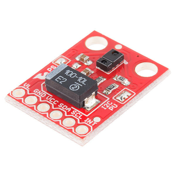
The APDS-9960 RGB and Gesture Sensor board breaks out the pins on the Avago APDS-9960 so you can easily use it in a variety of projects. The APDS-9960 uses the I2C interface for communications.
Covered In This Tutorial
In this tutorial, we will give an overview of the APDS-9960 sensor board and provide an example hookup and code. The tutorial is split into the following sections:
- Board Overview -- To begin, we'll go over each of the pins on the breakout board and their function. This section also overviews the jumpers on the front of the board.
- Hardware Hookup -- In this section, we'll show you how to hook the APDS-9960 up to an Arduino to detect gestures via I2C.
- Arduino Library Installation -- Here, we download and install the APDS-9960 Arduino library.
- Gesture Sensing Example -- We try out the sensor with the the GestureTest example.
- Resources and Going Further -- You made a simple gesture sensor, but where do you go from there? This section gives you some additional resources for getting more use out of the APDS-9960.
Materials Used
You will need a few components and tools to follow along with this tutorial. Here is what you will need:
If you do not have specifically a 3.3V Arduino Pro, there are a number of ways to complete the walkthrough. In general, you will need:
- Arduino or other microcontroller -- You will need something that is capable of I2C and communicating back to the computer (e.g. serial communications). The microcontroller needs to have a 3.3V I/O voltage or you will have to use a level shifter. We are using the 3.3V Arduino Pro, but the 3.3V Arduino Pro Mini would work as well.
- Level shifting -- If you are using a 5V Arduino, like the Uno or RedBoard, you will need to use a level shifter, such as the bi-directional logic level converter.
- Connectors -- You will need to interface your microcontroller with the breakout board. Male headers are perfect if you're using a breadboard. Another option is to use wire to connect the breakout board directly to the microcontroller.
- Soldering tools -- After you've picked a connector, you will need to solder it to the breakout board. A simple soldering iron and some solder should be all you need.
Recommended Reading
Before getting started with the APDS-9960, there are a few concepts that you should be familiar with. Consider reading some of these tutorials before continuing:
- What is an Arduino? -- We will use an Arduino to control the APDS-9960
- I2C -- I2C is the communication protocol used by the APDS-9960
- Serial Communication -- We use serial communications (with the FTDI breakout board) to program the Arduino and provide information to our computer from the Arduino
- How to Use a Breadboard -- The breadboard ties the Arduino to the APDS-9960 breakout board
Board Overview
Pin Descriptions
The APDS-9960 breakout board provides 6 pins to provide power to the sensor and I2C bus.
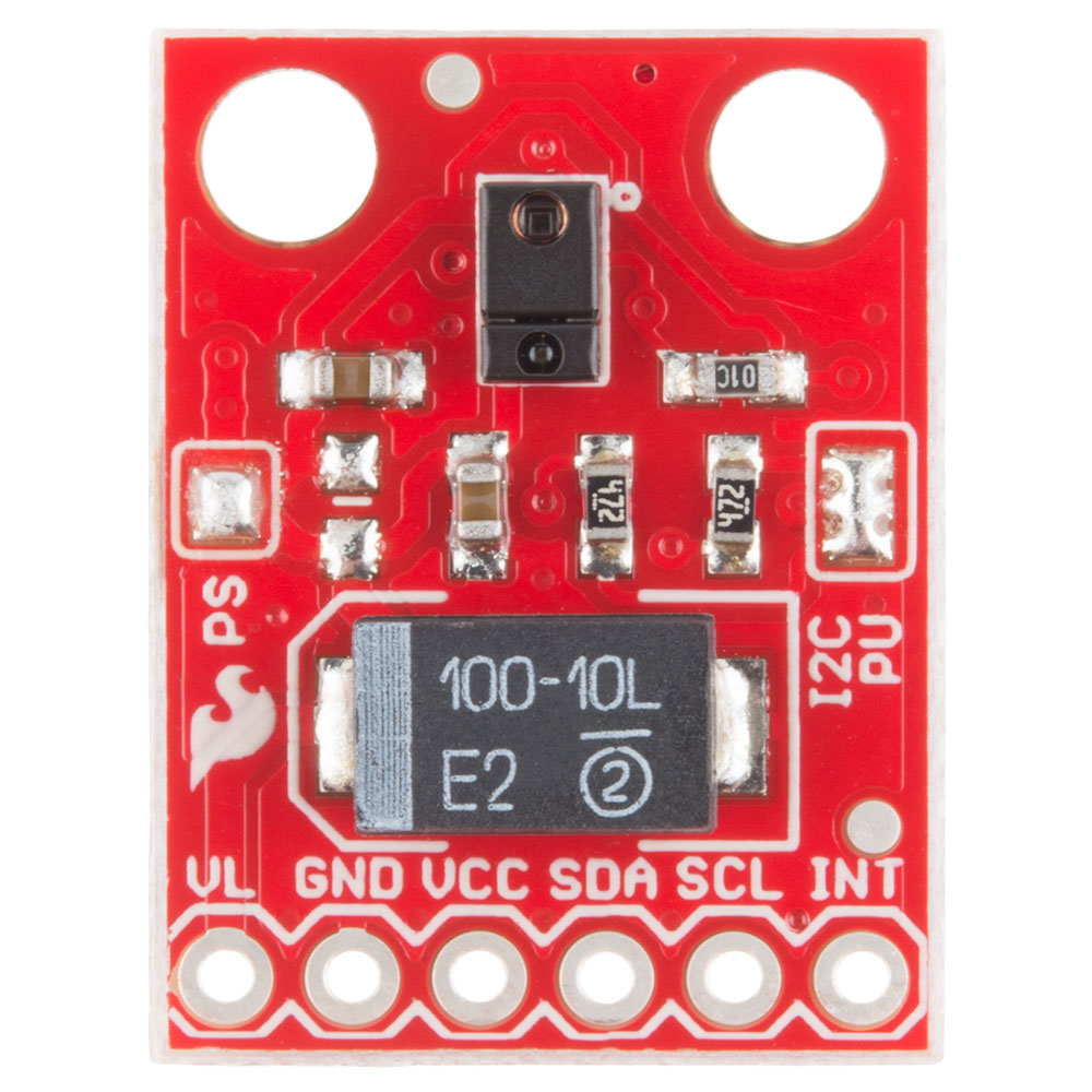
| Pin Label | Description |
|---|---|
| VL | Optional power to the IR LED if PS jumper is disconnected. Must be 3.0 - 4.5V |
| GND | Connect to ground. |
| VCC | Used to power the APDS-9960 sensor. Must be 2.4 - 3.6V |
| SDA | I2C data |
| SCL | I2C clock |
| INT | External interrupt pin. Active LOW on interrupt event |
Setting the Jumpers
On the front of the breakout board are 2 solder jumpers:
- PS -- This jumper connects the power supplies of the sensor and IR LED (also located on the APDS-9960) together. When the jumper is closed (i.e. connected), you only need to supply power to the VCC pin to power both the sensor and the IR LED. If the jumper is open, you need to provide power to both the VCC (2.4 - 3.6V) and VL (3.0 - 4.5V) pins separately. This jumper is closed by default.
- I2C PU -- This is a 3-way solder jumper that is used to connect and disconnect the I2C pullup resistors. By default, this jumper is closed, which means that both SDA and SCL lines have connected pullup resistors on the breakout board. Use some solder wick to open the jumper if you do not need the pullup resistors (e.g. you have pullup resistors that are located on the I2C bus somewhere else).
Hardware Hookup
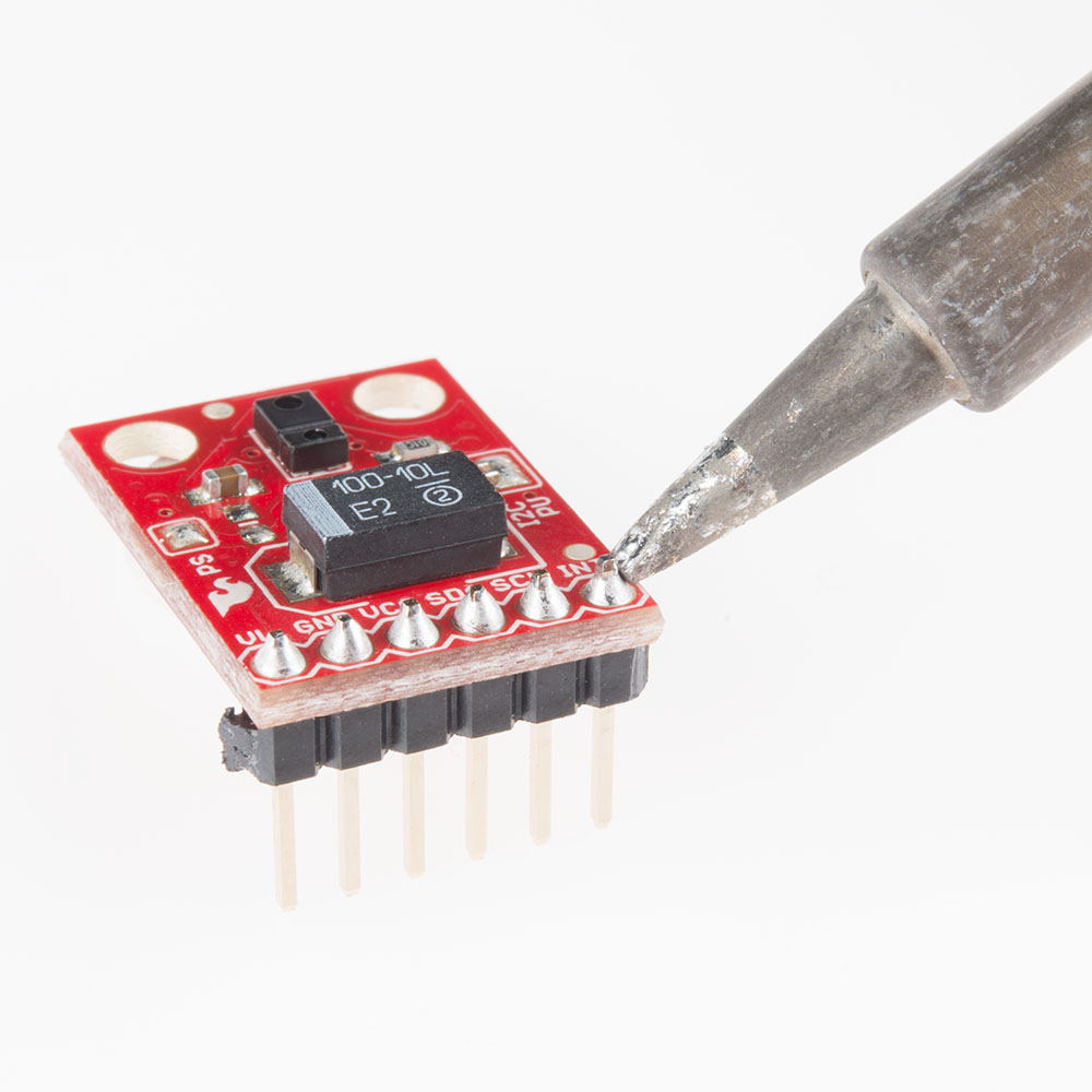
Add Headers
Solder a row of break away male headers to the 6 headers holes on the board.
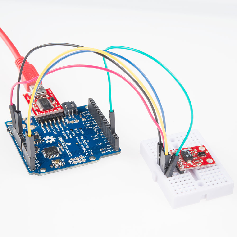
Connect the Breakout Board
We will be using the Arduino Pro's regulated 3.3V power and I2C bus with the APDS-9960. Note that we are leaving VL on the breakout board unconnected.
IMPORTANT: You must use 3.3V! If you try to use a 5V power supply or 5V I2C communications, you risk damaging the APDS-9960. If you are using a 5V Arduino (e.g. UNO), then you need to have some kind of level shifting.
Connect the breakout board to the following pins on the Arduino:
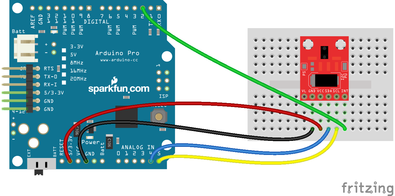
| APDS-9960 Breakout Board | Arduino Pro 3.3V |
|---|---|
| GND | GND |
| VCC | VCC |
| SDA | A4 |
| SCL | A5 |
| INT | 2 |
Arduino Library Installation
To use the APDS-9960, you will need some supporting software. If you are using an Arduino, then you are in luck! We created an Arduino library that makes the APDS-9960 easy to use. Click the button below to download the latest version of the APDS-9960 breakout board project, which includes the Arduino library.
Unzip the downloaded file and navigate to \

Follow this guide on installing Arduino libraries to install the files within the SparkFun_APDS9960 directory as an Arduino library.
Gesture Sensing Example
Load the GestureTest Example
Open up the Arduino program and select File → Examples → SparkFun_APDS9960 → GestureTest.

Plug in your FTDI Breakout (3.3V) to the Arduino Pro (3.3V). Attach a USB mini cable from your computer to the FTDI Breakout. If you have not previously done so, install the FTDI drivers.
For reference, here is the GestureTest.ino sketch.
language:c
/****************************************************************
GestureTest.ino
APDS-9960 RGB and Gesture Sensor
Shawn Hymel @ SparkFun Electronics
May 30, 2014
https://github.com/sparkfun/APDS-9960_RGB_and_Gesture_Sensor

Tests the gesture sensing abilities of the APDS-9960. Configures
APDS-9960 over I2C and waits for gesture events. Calculates the
direction of the swipe (up, down, left, right) and displays it
on a serial console.

To perform a NEAR gesture, hold your hand
far above the sensor and move it close to the sensor (within 2
inches). Hold your hand there for at least 1 second and move it
away.

To perform a FAR gesture, hold your hand within 2 inches of the
sensor for at least 1 second and then move it above (out of
range) of the sensor.

Hardware Connections:

IMPORTANT: The APDS-9960 can only accept 3.3V!

 Arduino Pin  APDS-9960 Board  Function

 3.3V         VCC              Power
 GND          GND              Ground
 A4           SDA              I2C Data
 A5           SCL              I2C Clock
 2            INT              Interrupt

Resources:
Include Wire.h and SparkFun_APDS-9960.h

Development environment specifics:
Written in Arduino 1.0.5
Tested with SparkFun Arduino Pro Mini 3.3V

This code is beerware; if you see me (or any other SparkFun
employee) at the local, and you've found our code helpful, please
buy us a round!

Distributed as-is; no warranty is given.
****************************************************************/

#include <Wire.h>
#include <SparkFun_APDS9960.h>

// Pins
#define APDS9960_INT    2 // Needs to be an interrupt pin

// Constants

// Global Variables
SparkFun_APDS9960 apds = SparkFun_APDS9960();
int isr_flag = 0;

void setup() {

  // Initialize Serial port
  Serial.begin(9600);
  Serial.println();
  Serial.println(F("--------------------------------"));
  Serial.println(F("SparkFun APDS-9960 - GestureTest"));
  Serial.println(F("--------------------------------"));

  // Initialize interrupt service routine
  attachInterrupt(0, interruptRoutine, FALLING);

  // Initialize APDS-9960 (configure I2C and initial values)
  if ( apds.init() ) {
    Serial.println(F("APDS-9960 initialization complete"));
  } else {
    Serial.println(F("Something went wrong during APDS-9960 init!"));
  }

  // Start running the APDS-9960 gesture sensor engine
  if ( apds.enableGestureSensor(true) ) {
    Serial.println(F("Gesture sensor is now running"));
  } else {
    Serial.println(F("Something went wrong during gesture sensor init!"));
  }
}

void loop() {
  if( isr_flag == 1 ) {
    detachInterrupt(0);
    handleGesture();
    isr_flag = 0;
    attachInterrupt(0, interruptRoutine, FALLING);
  }
}

void interruptRoutine() {
  isr_flag = 1;
}

void handleGesture() {
    if ( apds.isGestureAvailable() ) {
    switch ( apds.readGesture() ) {
      case DIR_UP:
        Serial.println("UP");
        break;
      case DIR_DOWN:
        Serial.println("DOWN");
        break;
      case DIR_LEFT:
        Serial.println("LEFT");
        break;
      case DIR_RIGHT:
        Serial.println("RIGHT");
        break;
      case DIR_NEAR:
        Serial.println("NEAR");
        break;
      case DIR_FAR:
        Serial.println("FAR");
        break;
      default:
        Serial.println("NONE");
    }
  }
}
Run
Make sure you have the correct serial port selected under Tools → Serial Port and "Arduino Pro or Pro Mini (3.3V, 8MHz) w/ ATmega328" selected under Tools → Board. If you have never used the Arduino IDE before, this turoial should get you started.
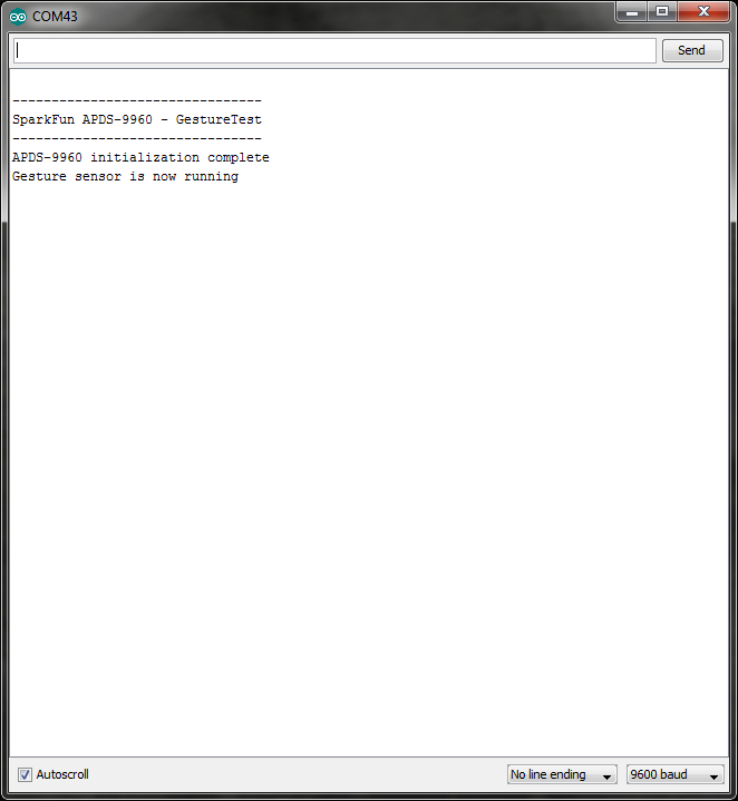
Click the Upload button and wait for the program to finish uploading to the Arduino. Select Tools → Serial Monitor to open up the serial terminal. More info on the Serial Terminal can be found here. You should see a couple of messages noting that "APDS-9960 initialization complete" and "Gesture sensor is now running."
Hover your hand 4 to 8 inches (10 to 20 cm) above the sensor but off to one side (i.e. not directly above the sensor). While maintaining the same height, swipe your hand over the sensor (into and then immediately out of range of the sensor). If you move too fast, the sensor will not recognize the gesture.
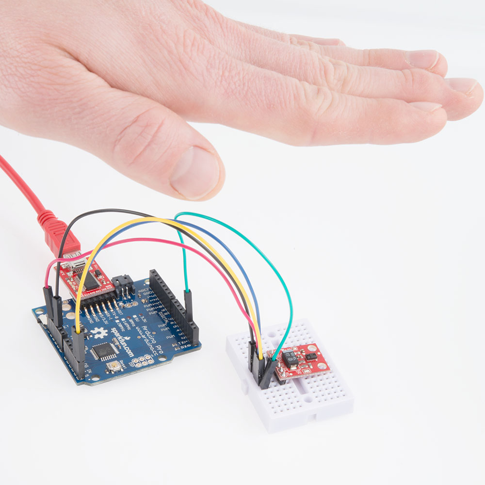
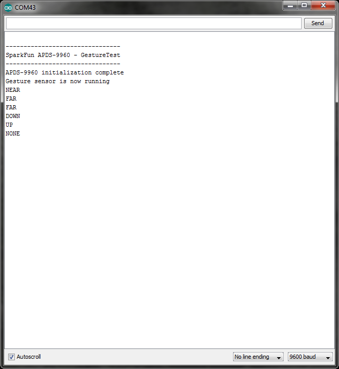
Gestures will appear on the serial monitor, which indicate the direction of the swipe.

There are also 2 other gestures available: NEAR and FAR.
A NEAR gesture can be achieved by holding your hand far above the sensor (greater than 10 inches (25 cm)), bringing it close to the sensor (about 2 inches (5 cm) directly above the sensor), holding it there for at least 1 second, and then removing your hand.
A FAR gesture can be achieved by holding your hand directly above and close to the sensor (about 2 inches (5 cm)) for at least 1 second and then moving your hand up directly above and out of range of the sensor.
If a gesture was not correctly interpreted, NONE will appear in the serial monitor.
Supported Gestures
Here is a list of the currently supported gestures. Make sure each gesture begins outside of the range of the sensor, moves into the range of the sensor, and ends outside the range of the sensor.
| Gesture | Description |
|---|---|
| UP | A swipe from the bottom of the board to the top and out of range of the sensor. Make sure that your wrist/arm is not in the sensor's range at the end of the swipe! |
| DOWN | A swipe from the top of the board to the bottom and out of range of the sensor. |
| LEFT | A swipe from the right side of the board to the left and out of range of the sensor. |
| RIGHT | A swipe from the left side of the board to the right and out of range of the sensor. |
| NEAR | Object (e.g. hand) starts far above the sensor, moves close to the sensor, hovers for at least 1 second, and moves out of range of the sensor. |
| FAR | Object starts near the sensor, hovers for at least 1 second, and then moves up above and out of range of the sensor. |
| NONE | The sensor could not correctly guess the gesture being performed. |
Resources and Going Further
Now that you have seen the gesture recognition capabilities of the APDS-9960, you can begin to use it in your project! Keep in mind that the APDS-9960 is also capable of sensing object proximity and ambient/color light. Try out the other examples in the SFE_APDS9960 library to see what the sensor can do:
- AmbientLightInterrupt -- This example shows how you can generate an Arduino interrupt whenever the ambient light falls below a given level. You can also change it to throw an interrupt when the light rises above a certain level.
- ColorSensor -- This demo shows how to read ambient, red, green, and blue light values from the APDS-9960.
- GestureTest -- We used this example in this hookup guide. It shows how to read basic gestures with the APDS-9960.
- ProximityInterrupt -- The APDS-9960 can be used to detect when objects move within range of its sensor. This example shows how to throw an interrupt whenever an object moves within a certain range of the sensor. You can also change the limits to generate an interrupt whenever an object moves outside of a certain range.
- ProximitySensor -- You do not need to use interrupts with the proximity sensor. In this demo, we show you how to poll the sensor for proximity data at regular intervals. Try running this example and moving your hand close to the sensor.
Resources
Here are some additional resources to help you with the APDS-9960:
- APDS-9960 Datasheet
- APDS-9960 Breakout Board Schematic
- APDS-9960 RGB and Gesture Sensor GitHub Repository
Other Tutorials
What will you make with the APDS-9960? If you need some inspiration, check out these related tutorials: