ADXL345 Hookup Guide
Introduction
The ADXL345 is a small, thin, low power, 3-axis MEMS accelerometer with high resolution (13-bit) measurement at up to +/-16 g. Digital output data is formatted as 16-bit two's complement and is accessible through either an SPI (3- or 4-wire) or I2C digital interface.
This hookup guide will explore the various functions of the ADXL345 utilizing the SparkFun ADXL345 Arduino Library and example code. First, let's get some background on this small yet powerful accelerometer.
As we step through the Hook Up Guide, you'll find it useful to have the ADXL345 Datasheet on hand.
Required Materials
The wish list below includes all of the materials that will be utilized in this tutorial:
**Note: ** If you plan on using the ADXL345 in I2C mode, you do not need to purchase the logic level converter from the list above.
Suggested Reading
If you're not sure if this product is right for your needs, check out the Accelerometer, Gyro and IMU Buying Guide. Some additional resources that might be helpful in this process, especially if you are just started out, you can find here:
How to Solder: Through-Hole Soldering
Working with Wire
Accelerometer Basics
I2C
Hardware Overview
Features
- Supply Voltage: 2.0 - 3.6 VDC
- Ultra Low Power: As low as 23 uA in measurement mode, 0.1uA in standby mode at 2.5V
- SPI or I2C Communication
- Single Tap / Double Tap Detection
- Activity / Inactivity Sensing
- Free-Fall Detection
Whoa! What are those last three?! Yes, the ADXL345 has special sensing abilities! The single and double tap sensing detects when a single, or two simultaneous, acceleration events occur. Activity and inactivity sensing detect the presence or lack of motion. Free-fall sensing compares the acceleration on all axes with the threshold value to know if the device is falling. All thresholds levels that trigger the activity, free-fall, and single tap/double tap events are user-set levels. These functions can also be mapped to one of two interrupt output pins. An integrated, patent pending 32-level first in, first out (FIFO) buffer can be used to store data to minimize host processor intervention.
The ADXL345 is well suited to measure the static acceleration of gravity in tilt-sensing applications, as well as dynamic acceleration resulting from motion or shock. Its high resolution (4 mg/LSB) enables measurement of inclination changes less than 1.0°. Furthermore, low power modes enable intelligent motion-based power management with threshold sensing and active acceleration measurement at extremely low power dissipation.
Applications
- Handsets
- Medical Instrumentation
- Gaming and Pointing Devices
- Industrial Instrumentation
- Personal Navigation Devices
- Hard Disk Drive (HDD) protection
Pin Functionality
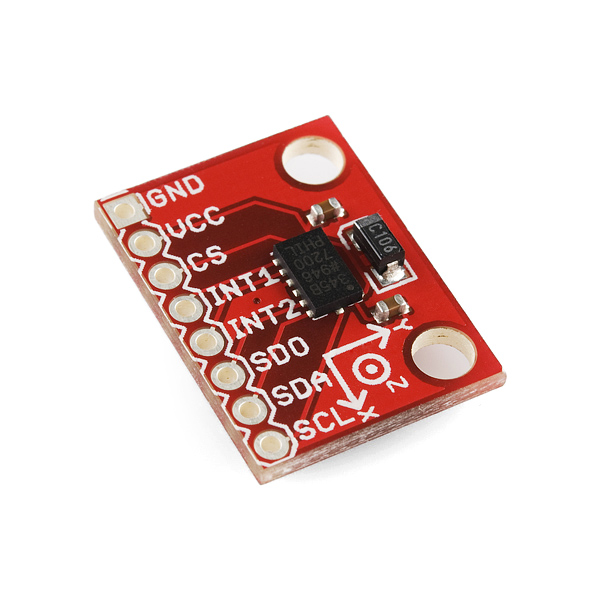
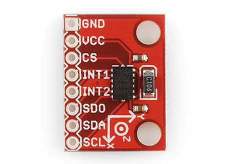
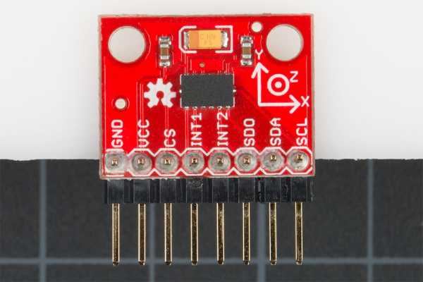
Below you can reference the ADXL345 breakout board and pin functions.
Breakout Board Pin Function Descriptions
| Mnemonic | Description |
| GND | This pin must be connected to ground |
| VCC | Supply Voltage |
| CS | Chip Select |
| INT1 | Interrupt 1 Output |
| INT2 | Interrupt 2 Output |
| SDO |
Serial Data Output (SPI 4-Wire) / I2C Address Select |
| SDA / SDI / SDIO |
Serial Data I2C / Serial Data Input (SPI 4-WIRE) / Serial Data Input and Output (SPI 3-Wire) |
| SCL/SCLK |
Serial Communications Clock |
Assembly
With the ADXL345, I2C and SPI digital communications are available. In both cases, the ADXL345 operates as a slave device.
Note: A potential problem when hooking up the ADXL345 breakout to an Arduino (or compatible board) is, if you are using a breadboard with loosely connected jumper wires, you risk getting bad data. Make sure your connections are solid, and you should be fine.
SPI Communication
First, we will look at how to connect an Arduino (or compatible board like SparkFun's RedBoard) to the ADXL345 breakout board for SPI communication.
In SPI mode, the CS pin is controlled by the bus master. For SPI, either 3- or 4- wire configuration is possible.
Note: When using 3-wire SPI, it is recommended that the SDO pin be pulled up to VDD I/O or pulled down to GND via a 10 kΩ resistor. Please refer to page 15 of the ADXL345 Datasheet for additional information.
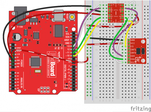
The following is a table describing which pins on the Arduino should be connected to the pins on the accelerometer for SPI 4-wire communication.
| Arduino Pin | ADXL345 Pin |
| GND | GND |
| 3V3 | VCC |
| 10 | CS |
| 12 | SDO |
| 11 | SDA |
| 13 |
SCL |
Here is a wiring connection diagram to aid you in hooking it up for SPI 4-wire communication.
I2C Communication
Now, let's look at how to connect an Arduino (or compatible board like SparkFun's RedBoard) to the ADXL345 breakout board for I2C communication.
I2C mode is enabled if the CS pin is tied to high. There is no default mode if the CS pin is left unconnected, so it should always be tied high or driven by an external controller.
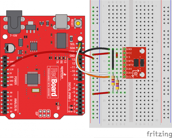
Note: If other devices are connected to the same I2C bus, the nominal operating voltage level of those other devices cannot exceed VDD I/O by more than 0.3 V. External pull-up resistors are necessary for proper I2C operation. Used in this connection diagram are two 4.7 kΩ resistors. Please refer to page 18 of the ADXL345 Datasheet for additional information.
The following is a table describing which pins on the Arduino should be connected to the pins on the accelerometer for I2C communication.
| Arduino Pin | ADXL345 Pin |
| GND | GND |
| 3V3 | VCC |
| 3V3 | CS |
| GND | SDO |
| A4 | SDA |
| A5 |
SCL |
Here is a wiring connection diagram to aid you in hooking it up for I2C communication.
Not using a SparkFun RedBoard or Arduino Uno? The reference table below shows where Two Wire Interface (TWI) pins are located on different and older Arduino boards.
| Board | I2C / TWI Pins |
| SparkFun Red, Uno, Ethernet | A4 (SDA), A5 (SCL) |
| Mega2560 | 20 (SDA), 21 (SCL) |
| Leonardo | 2 (SDA), 3 (SCL) |
| Due | 20 (SDA), 21 (SCL), SDA1, SCL1 |
SparkFun ADXL345 Library
The most exciting part of the Hookup Guide is the SparkFun ADXL345 library we've put together for you. Now, you not only have the ability to customize your sensing functions but also switch easily back and forth between I2C and SPI communication.
To get started, you can download the library here along with example code. For the most up-to-date code visit the SparkFun ADXL345 Arduino Library Repo.
SparkFun ADXL345 Library and Example Code
The downloaded file includes:
- Library .cpp and .h files
- Arduino Sketch: ADXL345 Calibration Example
- Arduino Sketch: ADXL345 Example
- Arduino Sketch: SparkFun Baby Blynk Monitor Thing Example
- README.md
- keywords.txt
Before we are able to use the example code, we need to place the SparkFun_ADXL345_Library folder into your Arduino Library. If you don't know where that is located, you can usually find it here:
Mac: (home directory) > Documents > Arduino > libraries
Linux: (home directory) > Sketchbook > Libraries
For help installing the library, check out our Installing an Arduino Library tutorial.
Using the SparkFun ADXL245 Library
Once you've installed the SparkFun ADXL345 Library, you can open up SparkFun_ADXL345_Example.ino in the Arduino IDE.
Make sure you have downloaded and installed the Arduino Software IDE so you can open the example code and program your board.
Example Code
Now that you have the example sketch open, let's go through and take a look at all the ways we can customize the ADXL345.
SPI or I2C?
The first important selection to make is under the COMMUNICATION SECTION. This is where you will let the library know whether you have setup your hardware for SPI or I2C communication.
language:c
/*********** COMMUNICATION SELECTION ***********/
/*    Comment Out The One You Are Not Using    */
ADXL345 adxl = ADXL345(10);           // USE FOR SPI COMMUNICATION, ADXL345(CS_PIN);
//ADXL345 adxl = ADXL345();             // USE FOR I2C COMMUNICATION
Make sure to comment out // the line of code you are not using. By default, the code has you utilizing SPI communication.
Setup
The most complex part of the example code is the void setup() section. This is where you'll be able to configure your settings and sensing feature thresholds.
language:c
/******************** SETUP ********************/
/*          Configure ADXL345 Settings         */
void setup(){

Serial.begin(9600);                 // Start the serial terminal
Serial.println("SparkFun ADXL345 Accelerometer Hook Up Guide Example");
Serial.println();

adxl.powerOn();                     // Power on the ADXL345

adxl.setRangeSetting(16);           // Give the range settings
                                    // Accepted values are 2g, 4g, 8g or 16g
                                    // Higher Values = Wider Measurement Range
                                    // Lower Values = Greater Sensitivity

adxl.setSpiBit(0);                  // Configure the device to be in 4 wire SPI mode when set to '0' or 3 wire SPI mode when set to 1
                                    // Default: Set to 1
                                    // SPI pins on the ATMega328: 11, 12 and 13 as reference in SPI Library

adxl.setActivityXYZ(1, 0, 0);       // Set to activate movement detection in the axes "adxl.setActivityXYZ(X, Y, Z);" (1 == ON, 0 == OFF)
adxl.setActivityThreshold(75);      // 62.5mg per increment   // Set activity   // Inactivity thresholds (0-255)

adxl.setInactivityXYZ(1, 0, 0);     // Set to detect inactivity in all the axes "adxl.setInactivityXYZ(X, Y, Z);" (1 == ON, 0 == OFF)
adxl.setInactivityThreshold(75);    // 62.5mg per increment   // Set inactivity // Inactivity thresholds (0-255)
adxl.setTimeInactivity(10);         // How many seconds of no activity is inactive?

adxl.setTapDetectionOnXYZ(0, 0, 1); // Detect taps in the directions turned ON "adxl.setTapDetectionOnX(X, Y, Z);" (1 == ON, 0 == OFF)

// Set values for what is considered a TAP and what is a DOUBLE TAP (0-255)
adxl.setTapThreshold(50);           // 62.5 mg per increment
adxl.setTapDuration(15);            // 625 μs per increment
adxl.setDoubleTapLatency(80);       // 1.25 ms per increment
adxl.setDoubleTapWindow(200);       // 1.25 ms per increment

// Set values for what is considered FREE FALL (0-255)
adxl.setFreeFallThreshold(7);       // (5 - 9) recommended - 62.5mg per increment
adxl.setFreeFallDuration(30);       // (20 - 70) recommended - 5ms per increment

// Setting all interupts to take place on INT1 pin
//adxl.setImportantInterruptMapping(1, 1, 1, 1, 1);     // Sets "adxl.setEveryInterruptMapping(single tap, double tap, free fall, activity, inactivity);"
                                                        // Accepts only 1 or 2 values for pins INT1 and INT2. This chooses the pin on the ADXL345 to use for Interrupts.
                                                        // This library may have a problem using INT2 pin. Default to INT1 pin.

// Turn on Interrupts for each mode (1 == ON, 0 == OFF)
adxl.InactivityINT(1);
adxl.ActivityINT(1);
adxl.FreeFallINT(1);
adxl.doubleTapINT(1);
adxl.singleTapINT(1);

//attachInterrupt(digitalPinToInterrupt(interruptPin), ADXL_ISR, RISING);   // Attach Interrupt

}
The comments can help guide you as to what each function does along with recommended ranges to stay within where applicable. More detailed information of the sensing functions and interrupts can be found on the ADXL345 Datasheet.
Main Code
The main example code was kept very simple. It focuses on not only reading the accelerometer values but also checking to see if any interrupts have occurred.
language:c
/****************** MAIN CODE ******************/
/*     Accelerometer Readings and Interrupt    */
void loop(){

// Accelerometer Readings
int x,y,z;
adxl.readAccel(&x, &y, &z);         // Read the accelerometer values and store them in variables declared above x,y,z

// Output Results to Serial
/* UNCOMMENT TO VIEW X Y Z ACCELEROMETER VALUES */
//Serial.print(x);
//Serial.print(", ");
//Serial.print(y);
//Serial.print(", ");
//Serial.println(z);

ADXL_ISR();
// You may also choose to avoid using interrupts and simply run the functions within ADXL_ISR();
//  and place it within the loop instead.
// This may come in handy when it doesn't matter when the action occurs.

}
Currently, the sketch will only output free fall detection, inactivity/activity, and single/double tap detection to the Serial Monitor.
In order to print the measured accelerometer values to the Serial Monitor, just remember to uncomment the following section to look like this:
language:c
// Output Results to Serial
/* UNCOMMENT TO VIEW X Y Z ACCELEROMETER VALUES */
Serial.print(x);
Serial.print(", ");
Serial.print(y);
Serial.print(", ");
Serial.println(z);
Serial Monitor Output
Let's see it in action! Go to Tools on your Arduino IDE, set your board and port, and upload the SparkFun_ADXL345_Example.ino sketch to your Arduino or compatible board. If you need further assistance in uploading your sketch this might be helpful: Uploading a Sketch.
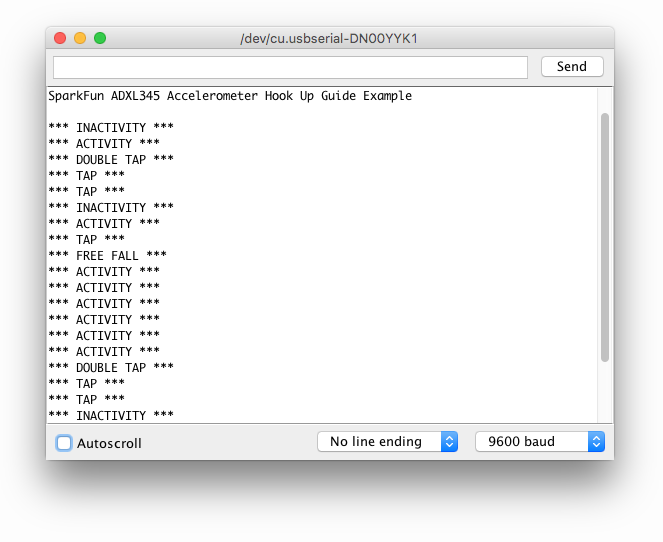
The following two Serial Monitor outputs are what you should expect whether you have commented out the accelerometer values from being displayed or not.
Accelerometer Values Excluded
This is what your outputs will look like with the sensing features are triggered.
Accelerometer Values Included
This is the data you should see when you have uncommented the X, Y and Z Serial.print() lines of code. Also, keep in mind you will still see when the sensing features are triggered, it just might be harder to catch amongst the data stream.
Calibration
The other sketch available to you is the SparkFun_ADXL345_Calibration.ino. This will be useful whenever you have an application that requires your device to be precision calibrated.
Calibration Method
An accurate calibration method is to use two points per axis. In our case we have a three-axis design, therefore, we are interested in six points. In the datasheet and in the example sketch, you'll notice references to the g range with accepted values of 2g, 4g, 8g or 16g. 1g is equivalent to the force of gravity acting on a stationary object resting on Earth's surface. Acceleration relative to gravity can be measured in units of gravitational force.
A great resource is the Application Note from Analog Devices: Using an Accelerometer for Inclination Sensing
Calibration Example Sketch
Here is what the calibration example sketch looks like:
language:c
#include <SparkFun_ADXL345.h>

/*********** COMMUNICATION SELECTION ***********/
/*    Comment Out The One You Are Not Using    */
//ADXL345 adxl = ADXL345(10);           // Use when you want to use Hardware SPI, ADXL345(CS_PIN);
ADXL345 adxl = ADXL345();             // Use when you need I2C

/****************** VARIABLES ******************/
/*                                             */
int AccelMinX = 0;
int AccelMaxX = 0;
int AccelMinY = 0;
int AccelMaxY = 0;
int AccelMinZ = 0;
int AccelMaxZ = 0;

int accX = 0;
int accY = 0;
int accZ = 0;

int pitch = 0;
int roll = 0;

/************** DEFINED VARIABLES **************/
/*                                             */
#define offsetX   0       // OFFSET values
#define offsetY   0
#define offsetZ   0

#define gainX     1     // GAIN factors
#define gainY     1
#define gainZ     1

/******************** SETUP ********************/
/*          Configure ADXL345 Settings         */
void setup()
{
Serial.begin(9600);                 // Start the serial terminal
Serial.println("SparkFun ADXL345 Accelerometer Breakout Calibration");
Serial.println();

adxl.powerOn();                     // Power on the ADXL345

adxl.setRangeSetting(2);           // Give the range settings
                                    // Accepted values are 2g, 4g, 8g or 16g
                                    // Higher Values = Wider Measurement Range
                                    // Lower Values = Greater Sensitivity

adxl.setSpiBit(0);                // Configure the device to be in 4 wire SPI mode when set to '0' or 3 wire SPI mode when set to 1
                                    // It is set to 1 by Default.
                                    // SPI pins on the ATMega328 as reference in SPI Library are 11, 12, and 13

}

/****************** MAIN CODE ******************/
/*  Accelerometer Readings and Min/Max Values  */
void loop()
{
Serial.println("Send any character to display values.");
while (!Serial.available()){}       // Waiting for character to be sent to Serial
Serial.println();

// Get the Accelerometer Readings
int x,y,z;                          // init variables hold results
adxl.readAccel(&x, &y, &z);         // Read the accelerometer values and store them in variables declared above x,y,z

if(x < AccelMinX) AccelMinX = x;
if(x > AccelMaxX) AccelMaxX = x;

if(y < AccelMinY) AccelMinY = y;
if(y > AccelMaxY) AccelMaxY = y;

if(z < AccelMinZ) AccelMinZ = z;
if(z > AccelMaxZ) AccelMaxZ = z;

Serial.print("Accel Minimums: "); Serial.print(AccelMinX); Serial.print("  ");Serial.print(AccelMinY); Serial.print("  "); Serial.print(AccelMinZ); Serial.println();
Serial.print("Accel Maximums: "); Serial.print(AccelMaxX); Serial.print("  ");Serial.print(AccelMaxY); Serial.print("  "); Serial.print(AccelMaxZ); Serial.println();
Serial.println();


/* Note: Must perform offset and gain calculations prior to seeing updated results
/  Refer to SparkFun ADXL345 Hook Up Guide: https://learn.sparkfun.com/tutorials/adxl345-hookup-guide
/  offsetAxis = 0.5 * (Acel+1g + Accel-1g)
/  gainAxis = 0.5 * ((Acel+1g - Accel-1g)/1g) */

// UNCOMMENT SECTION TO VIEW NEW VALUES
//accX = (x - offsetX)/gainX;         // Calculating New Values for X, Y and Z
//accY = (y - offsetY)/gainY;
//accZ = (z - offsetZ)/gainZ;

//Serial.print("New Calibrated Values: "); Serial.print(accX); Serial.print("  "); Serial.print(accY); Serial.print("  "); Serial.print(accZ);
//Serial.println();

while (Serial.available())
{
    Serial.read();                    // Clear buffer
}
}
The main code will read your accelerometer maximums and minimums. With these values we will be able to calculate the offset values and gain factors giving us our new calibrated accelerometer readings. We will talk more about the equations for those calculations in a minute.
Mounting Accelerometer
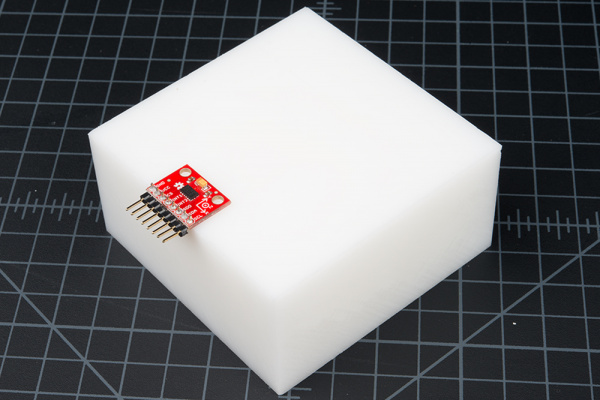
Before taking these measurements, we want to have the accelerometer mounted with the Z axis parallel to the up direction. For example, if our accelerometer is on a table, our ADXL345 breakout board will be oriented like the picture below and the Z data should be constant.
Make sure it's secure to either your application or a block that has a level flat surface.
Load Sketch and Take Measurements
Load the Calibration Sketch to your board. Open the Serial Monitor, and wait for the prompt that says to Send any character to display values. Each time you want to measure a different axis, simply turn the enclosure or block the ADXL345 breakout is mounted on, type a character to the Serial Monitor, and hit return to print out the measurement result. You'll notice an X-Y-Z axis symbol on the breakout board that will help with orienting in each direction.
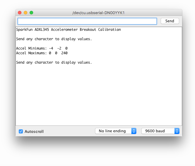
When an axis is placed into a +1 g and −1 g field, the measured outputs will look something like this on your Serial Monitor. You'll want to take measurements in each axis direction.
Recording Data
To leave room for offset and gain adjustments, it's probably best to do the calculations by hand. Record your data in a similar table like the one below.
| +1 g | -1 g | Offset | Gain | |
| X-Axis | ||||
| Y-Axis | ||||
| Z-Axis |
Calculations
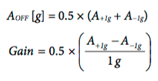
The offset values and gain factors are calculated with the following equations as stated in the Application Note from Analog Devices (page 8: equations 17 and 18).
In the DEFINED VARIABLES section of the code is where we will place the new calculated values for offset and gain.
language:c
/************** DEFINED VARIABLES **************/
/*                                             */
#define offsetX     0    // OFFSET values
#define offsetY     0
#define offsetZ     0

#define gainX       1     // GAIN factors
#define gainY       1
#define gainZ       1
Hooray! Now you'll be able to acquire the adjusted values for X, Y and Z.
Note: You'll have to uncomment a section of the following code to see your new calibrated values:
language:c
// UNCOMMENT SECTION TO VIEW NEW VALUES
accX = (x - offsetX)/gainX;         // Calculating New Values for X, Y and Z
accY = (y - offsetY)/gainY;
accZ = (z - offsetZ)/gainZ;

Serial.print("New Calibrated Values: "); Serial.print(accX); Serial.print("  "); Serial.print(accY); Serial.print("  "); Serial.print(accZ);
Serial.println();
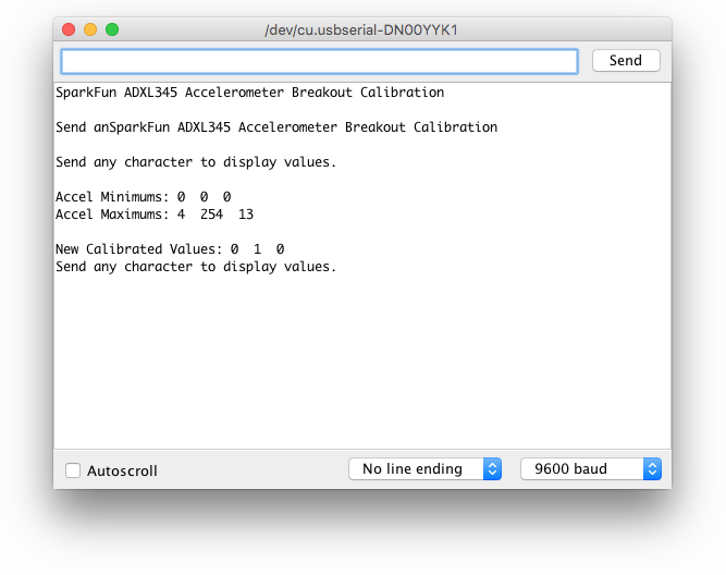
Now your Serial Monitor output will be calibrated and look something more like this...
Resources and Going Further
The SparkFun Triple Access Accelerometer ADXL345 and the ADXL345 Arduino Library are both open-source, so there are plenty of resources, including:
- SparkFun ADXL345 GitHub Repository
- SparkFun ADXL345 Eagle Files
- SparkFun ADXL345 Schematic
- SparkFun ADXL345 Arduino Library GitHub Repository
For more information on the ADXL345, the datasheet can be referred to.
ADXL345 Accelerometer Project Inspiration
Need some inspiration for your next project? Check out some of these related tutorials.
 |
| Motion Controlled Elevator TARDIS Tutorial |
Dungeons and Dragons Dice Gauntlet
Das Blinken Top Hat
Blynk Board Washer/Dryer Alarm
Or check out some of these blog posts for ideas:
