Reading and Writing Serial EEPROMs
 Nate,
Nate,  Nick Poole
 Introduction
EEPROM, or Electrically Erasable Programmable Read-Only Memory, is a type of device that allows you to store small chunks of data and retrieve it later even if the device has been power cycled. A lot of modern microcontrollers – such as the ATmega328 – contain some built-in EEPROM, but that doesn't mean that you can't add more! Serial EEPROM devices like the Microchip 24-series EEPROM allow you to add more memory to any device that can speak I²C. Today we're going to learn how to read and write serial EEPROM devices using Arduino.
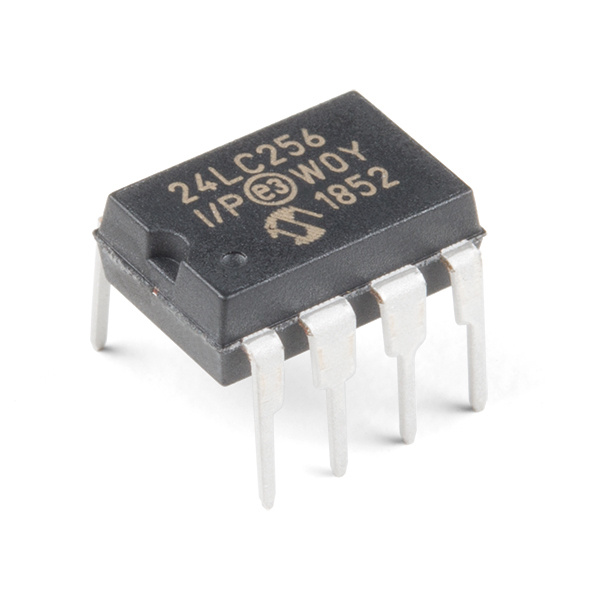
I2C EEPROM - 256k Bit (24LC256)
COM-00525Required Materials
To follow along with this tutorial, you will need the following materials. You may not need everything though depending on what you have. Add it to your cart, read through the guide, and adjust the cart as necessary.


I2C EEPROM - 256k Bit (24LC256)
COM-00525Suggested Reading
Before continuing with this guide, we recommend you be somewhat familiar with the concepts in the following tutorials:
How to Use a Breadboard
What is an Arduino?
Integrated Circuits
I2C
EEPROM Basics
Before we get into the hookup it's probably a good idea to familiarize ourselves with EEPROM and the history of ROM in general. That said, if you don't nerd-out on computer history it's probably safe to skip that section.
What is ROM?
Read-Only Memory (ROM) is a type of computer memory which, generally speaking, is only programmed once (or very occasionally) and then gets read from the rest of the time. This is because it's very slow — or impossible — to write new data to ROM. The trade-off for very slow write times — traditionally — is that it's also non-volatile meaning that the data doesn't go away when power is removed from the device. This makes it ideal for things like firmware which need to be "remembered" by the computer, but never actually change. The BIOS in your PC is stored on a form of ROM.
A Brief History of ROM
Early "Stored-Program" type computers — such as desk calculators and keyboard interpreters — began using ROM in the form of Diode Matrix ROM. This was memory made up of discrete semiconductor diodes placed on a specially organized PCB. This gave way to Mask ROM with the advent of integrated circuits. Mask ROM was a lot like Diode Matrix ROM only it was implemented on a much smaller scale. This meant, however, that you couldn't just move a couple of diodes around with a soldering iron and reprogram it. Mask ROM had to be programmed by the manufacturer and was thereafter not alterable.
Unfortunately, Mask ROM was expensive and took a long time to produce because each new program required a brand new device to be manufactured by a foundry. In 1956, however, this problem was solved with the invention of PROM (Programmable ROM) which allowed developers to program the chips themselves. That meant manufacturers could produce millions of the same unprogrammed device which made it cheaper and more practical. PROM, however, could only be written to once using a high-voltage programming device. After a PROM device was programmed, there was no way to return the device to its unprogrammed state.
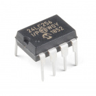
This changed in 1971 with the invention of EPROM (Erasable Programmable ROM) which — besides adding another letter to the acronym — brought with it the ability to erase the device and return it to a "blank" state using a strong UV light source. That's right, you had to shine a bright light on the IC to reprogram it, how cool is that? Well, it turns out it's pretty cool unless you're a developer working on firmware in which case you'd really like to be able to reprogram the device using electrical signals. This finally became a reality in 1983 with the development of EEPROM (Electrically Erasable Programmable ROM) and with that, we arrive at the current day unwieldy acronym.
Quirks of EEPROM
There are two major drawbacks to EEPROM as a method of data storage. In most applications the pros outweigh the cons, but you should be aware of them before incorporating EEPROM into your next design.
First of all, the technology that makes EEPROM work also limits the number of times that it can be re-written. This has to do with electrons becoming trapped in the transistors that make up the ROM and building up until the charge difference between a "1" and a "0" is unrecognizable. But don't worry, most EEPROMs have a maximum re-write number of 1 million or more. As long as you're not continuously writing to the EERPROM it's unlikely you'll hit this maximum.
Secondly, EEPROM will not be erased if you remove power from it, but it won't hold onto your data indefinitely. Electrons can drift out of the transistors and through the insulator, effectively erasing the EEPROM over time. That said, this usually occurs over the course of years (although it can be accelerated by heat). Most manufacturers say that your data is safe on EEPROM for 10 years or more at room temperature.
And there's one more thing you should keep in mind when selecting an EEPROM device for your project. EEPROM capacity is measured in bits and not bytes. A 256K EEPROM will hold 256Kbits of data, in other words, just 32KB.
Arduino Hardware Hookup
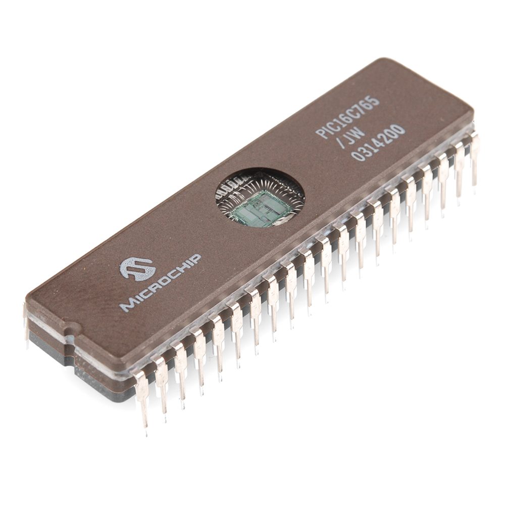
Okay, now that we know what EEPROM is, let's hook one up and see what it can do! In order to get our device talking we'll need to connect power as well as I²C serial lines. This device in particular runs at 5VDC so we'll connect it to the 5V output of our Arduino UNO. Also, the I²C lines will need pullup resistors for communication to happen correctly. The value of these resistors depends on the capacitance of the lines and frequency you want to communicate at, but a good rule of thumb for non-critical applications is just keep it in the kΩ range. In this example, we'll use 4.7kΩ pullup resistors.
There are three pins on this device to select the I²C address, this way you can have more than one EEPROM on the bus and address them each differently. You could just ground them all, but we'll be wiring them so that we can drop in a higher-capacity device later in the tutorial.
We'll use a breadboard to connect everything together. The diagram below shows the correct hookup for most I²C EEPROM devices, including the Microchip 24-series EEPROM that we sell.
That's it! Like most I²C devices, the hardware hookup is a breeze. Now we can move on to the code.
Reading and Writing
Most of the time when you're using an EEPROM in conjunction with a microcontroller you won't actually need to see all of the contents of the memory at once. You'll just read and write bytes here and there as needed. In this example, however, we're going to write an entire file to EEPROM and then read all of it back off so we can view it on our computer. This should get us comfortable with the idea of using EEPROM and also give us a feeling for how much data can really fit on a small device.
To send and receive files using the example Arduino sketches below, you'll need a terminal program such as TeraTerm. Once you have that downloaded and installed, we can get down to business.
Write Something
Our example sketch will simply take any byte that comes in over the serial port and write it to the EEPROM, keeping track along the way of how many bytes we've written to memory.
Writing a byte of memory to the EEPROM generally happens in three steps:
- Send the Most Significant Byte of the memory address that you want to write to.
- Send the Least Significant Byte of the memory address that you want to write to.
- Send the data byte that you would like to store at this location.
There are probably a few key words there that bare explaining:
Memory Addresses
If you imagine all of the bytes in a 256 Kbit EEPROM standing in a line from 0 to 32000 — because there are 8 bits to a byte and therefore you can fit 32000 bytes on a 256 Kbit EEPROM — then a memory address is the place in line where you would find a particular byte. We need to send that address to the EEPROM so it knows where to put the byte that we're sending.
Most Significant and Least Significant Bytes
Because there are 32000 possible places in a 256 Kbit EEPROM — and because 255 is the largest number you can encode in one byte — we need to send this address in two bytes. First we send the Most Significant Byte (MSB) — the first 8 bits in this case. Then we send the Least Significant Byte (LSB) — the second 8 bits. Why? Because this is how the device expects to receive them, that's all.
Page Writing
Writing one byte at a time is fine, but most EEPROM devices have something called a "page write buffer" which allows you to write multiple bytes at a time the same way you would a single byte. We'll be taking advantage of this in our example sketch.
The EEPROM uses an internal counter that automatically increases the memory location with each following data byte it receives. Once a memory address has been sent we can follow it with up to 64 bytes of data. The EEPROM assumes (rightly) that an address of 312 followed by 10 bytes will record byte 0 at address 312, byte 1 at address 313, byte 2 at address 314, and so on.
Arduino Sketch Example Write Something
Note: This example assumes you are using the latest version of the Arduino IDE on your desktop. If this is your first time using Arduino, please review our tutorial on installing the Arduino IDE.
Here's an example sketch to write some data to the EEPROM. Walk through the comments in the code for an explanation about what's going on.
language:c
//Include the Wire I2C Library
#include <Wire.h>

/*This address is determined by the way your address pins are wired.
In the diagram from earlier, we connected A0 and A1 to Ground and
A2 to 5V. To get the address, we start with the control code from
the datasheet (1010) and add the logic state for each address pin
in the order A2, A1, A0 (100) which gives us 0b1010100, or in
Hexadecimal, 0x54*/

#define EEPROM_ADR 0x54

/*Theoretically, the 24LC256 has a 64-byte page write buffer but
we'll write 16 at a time to be safe*/

#define MAX_I2C_WRITE 16

byte tempStore[MAX_I2C_WRITE];

void setup()
{

//Start the I2C Library
  Wire.begin();
  Wire.setClock(400000);

//Start the serial port
  Serial.begin(19200);

//Here is where we'll keep track of where in the memory we're writing
  long currentSpot = 0;
  long timerReset = 0;
  byte counter = 0;

  //Here we listen for bytes on the serial port and increment
  //the counter as we store them in our tempStore variable
  while (1)
  {
    while (Serial.available())
    {
      tempStore[counter++] = Serial.read(); //Read this byte into the array

      if (counter == MAX_I2C_WRITE)
      {
      //Once we've collected a page worth, go ahead and do
      //a page write operation
        writeEEPROMPage(currentSpot);
        counter = 0; //Reset
        currentSpot += MAX_I2C_WRITE;
      }

      timerReset = millis();
    }

    if (millis() - timerReset > 2000)
    {
      Serial.println(currentSpot);
      timerReset = millis();
    }
  }

}

void loop()
{
    // Don't do anything here
}

/* This is the 3 step memory writing procedure that
we talked about. First we send the MSB of the address.
Then we send the LSB of the address. Then we send the
data that we want to store. */

void writeEEPROMPage(long eeAddress)
{

  Wire.beginTransmission(EEPROM_ADR);

  Wire.write((int)(eeAddress >> 8)); // MSB
  Wire.write((int)(eeAddress & 0xFF)); // LSB

  //Write bytes to EEPROM
  for (byte x = 0 ; x < MAX_I2C_WRITE ; x++)
    Wire.write(tempStore[x]); //Write the data

  Wire.endTransmission(); //Send stop condition
}
Upload this code to your Arduino board and open the terminal program that you installed earlier. For the purposes of this tutorial, I'll assume you're using TeraTerm.
When you open TeraTerm, it will ask you to setup a new connection:
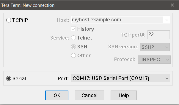
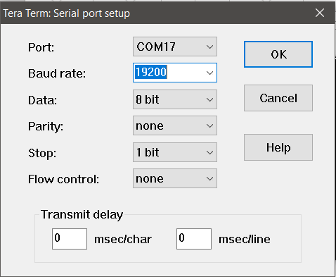
You'll need to select the serial port that your Arduino is connected to. Once you've pressed OK on that, go to Setup > Serial Port and set your Baud Rate to the one we selected in the code above (19200) then press OK.
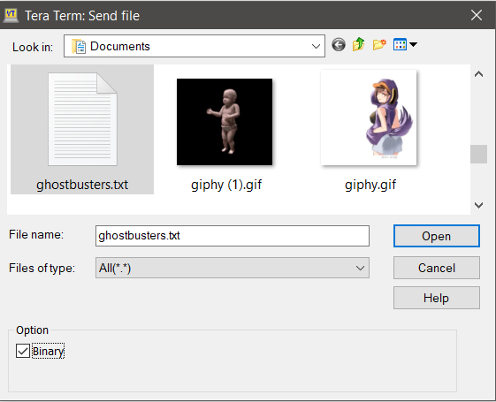
Now you should be seeing a bunch of zeros appearing in your terminal window. This is our sketch telling us how many bytes we've written. So far we've written nothing; let's change that! Go to File > Send File... and select a file to send through the terminal. For testing purposes, I suggest using the complete text of the Ghostbusters theme as written and performed by Ray Parker Jr. You can get the text file below.
Select that file and be sure to click on the "binary" button, so that the file is written byte-for-byte over the serial port.
When you press "Open" you'll see a file transfer window for just a moment as the file is dumped to the terminal.
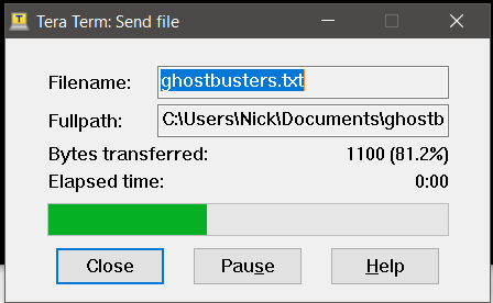
Now the number in your terminal window should be 1344, representing the memory location that we're sitting at after writing the complete text of the Ghostbusters theme as written and performed by Ray Parker Jr. You can go ahead and close TeraTerm, it worked! Well... we don't actually know if it worked until we read it back, so let's read it back!
Read Something
Reading from the EEPROM basically follows the same three step process as writing to the EEPROM:
- Send the Most Significant Byte of the memory address that you want to write to.
- Send the Least Significant Byte of the memory address that you want to write to.
- Ask for the data byte at that location.
Arduino Sketch Example Read Something
Here's an example sketch to write some data to the EEPROM. Walk through the comments in the code for an explanation about what's going on.
language:c
//Include the Wire I2C Library
#include <Wire.h>

/*This address is determined by the way your address pins are wired.
In the diagram from earlier, we connected A0 and A1 to Ground and
A2 to 5V. To get the address, we start with the control code from
the datasheet (1010) and add the logic state for each address pin
in the order A2, A1, A0 (100) which gives us 0b1010100, or in
Hexadecimal, 0x54*/

#define EEPROM_ADR 0x54

void setup()
{

//Start the I2C Library
  Wire.begin();
  Wire.setClock(400000);

//Start the serial port
  Serial.begin(115200);

  //Output raw bytes to terminal
  //In this case we're going to read all of the bytes
  //which is 32000, or in hex, 0x7D00
  for (long x = 0 ; x < 0x7D00 ; x++) //Read all 131,071 bytes from EERPOM
  {
    byte val = readEEPROM(x);
    Serial.write(val);
  }
}

void loop()
{
  //Nothing to do, just hang out.
}

/* This is the 3 step memory reading procedure that
we talked about. First we send the MSB of the address.
Then we send the LSB of the address. Then we ask for the
number of bytes that we want to receive. Here, we're
going 1 byte at a time*/

byte readEEPROM(long eeaddress)
{
  Wire.beginTransmission(EEPROM_ADR);

  Wire.write((int)(eeaddress >> 8)); // MSB
  Wire.write((int)(eeaddress & 0xFF)); // LSB
  Wire.endTransmission();

  Wire.requestFrom(EEPROM_ADR, 1);

  byte rdata = 0xFF;
  if (Wire.available()) rdata = Wire.read();
  return rdata;
}
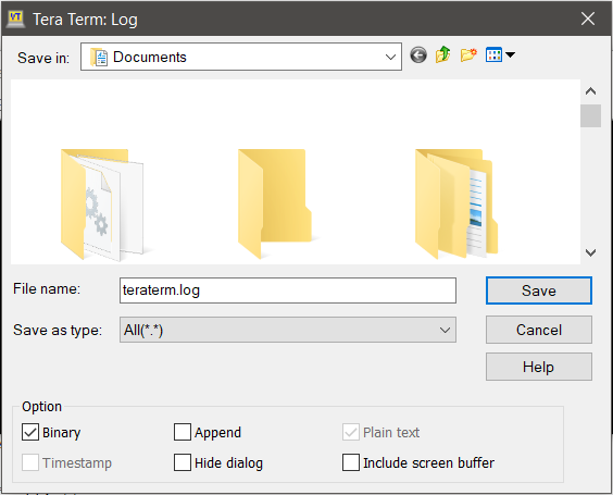
Now load this sketch onto your Arduino and open TeraTerm again. Once again, you'll need to open the correct serial port but before we set the correct baud rate and get things moving, let's create a file to store all the memory that we're about to read. Go to File > Log... and create a logfile. Make sure to uncheck the "Append" option and check the "Binary" option. This makes sure that the terminal will start a fresh logfile and write to it byte-for-byte what comes over the terminal.
When you press "Save" another dialog window will appear but it may pop under the current window Go find it, it will come in handy in a second. Now go to Setup > Serial Port and set your Baud Rate to the one we selected in the code above (115200) then press OK. Check the logfile window and see how many bytes have been transferred.
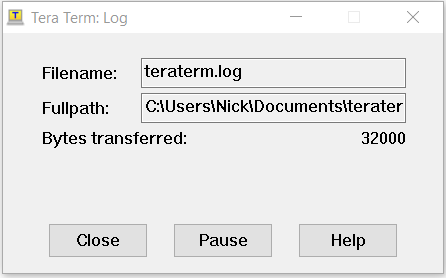
Once we've transferred 32000 bytes, we've got everything on the chip. Now close everything and open up that logfile in a text editor. You should now be face to face with, you guessed it, the complete text of the Ghostbusters theme as written and performed by Ray Parker Jr. Oh yeah, plus a bunch of junk that represents the unwritten space in memory.
Higher Capacity EEPROMs
So what if the thing that we want to store is bigger than complete text of the Ghostbusters theme as written and performed by Ray Parker Jr? As it happens, you can get EEPROM devices with much larger storage. For instance, the Microchip 24LC1025 can store up to 1025 Kbits! That's 128KB, enough space to have some real fun with!
Using the Microchip 24LC1025 is almost exactly like using the smaller EEPROM devices but with one minor tweak. Because the memory space is so much larger, two bytes is no longer enough to represent the memory address that we want to modify. To get around this problem, the 24LC1025 splits up the memory addresses into two separate blocks. When you address the chip, you send the block selector for the block that you want to manipulate in place of where you'd usually send the first bit of the chip address. Because of this, pin A2 on the EEPROM isn't used and needs to be tied to 5V in order for the device to work. You'll notice that we've already tied A2 to 5V in our previous example, so you could use the same example circuit to hook it up!
Arduino Sketch Example Write Something in a Higher Capacity EEPROM
Along with that change to our Arduino hookup, we'll also need to add to our code in order to switch the block select when we reach above a certain memory address. Here's what that operation looks like when we're writing:
language:c
void writeEEPROM(long eeAddress, byte data)
{
  if (eeAddress < 65536)
  {
    Wire.beginTransmission(EEPROM_ADR_LOW_BLOCK);
    eeAddress &= 0xFFFF; //Erase the first 16 bits of the long variable
  }
  else
  {
    Wire.beginTransmission(EEPROM_ADR_HIGH_BLOCK);
  }

  Wire.write((int)(eeAddress >> 8)); // MSB
  Wire.write((int)(eeAddress & 0xFF)); // LSB
  Wire.write(data);
  Wire.endTransmission();
}
Arduino Sketch Example Read Something in a Higher Capacity EEPROM
...and here it is when we're reading:
language:c
byte readEEPROM(long eeaddress)
{
  if (eeaddress < 65536)
    Wire.beginTransmission(EEPROM_ADR_LOW_BLOCK);
  else
    Wire.beginTransmission(EEPROM_ADR_HIGH_BLOCK);

  Wire.write((int)(eeaddress >> 8)); // MSB
  Wire.write((int)(eeaddress & 0xFF)); // LSB
  Wire.endTransmission();

  if (eeaddress < 65536)
    Wire.requestFrom(EEPROM_ADR_LOW_BLOCK, 1);
  else
    Wire.requestFrom(EEPROM_ADR_HIGH_BLOCK, 1);

  byte rdata = 0xFF;
  if (Wire.available()) rdata = Wire.read();
  return rdata;
}
It's just that easy! You can get the complete Arduino example sketches here if you want to play with it yourself:
Resources and Going Further
Now that you know how to read and write serial EEPROMs, you can have all kinds of fun with your Arduino! Why stop at song lyrics? Why not store journals or bitmaps... or even sensor readings? Actually, to think of it, sensor readings are probably the most practical thing to use it for...
For more information on the Microchip 24-series EEPROM, check out the resources below:
- Datasheet (PDF)
- Ghostbusters (TXT)
- Arduino Sketch Examples
But wait, if you're mad with power and want even more storage for your Arduino then you should check out this awesome tutorial on the MicroSD Card Breakout!