SparkFun GPS-RTK Dead Reckoning ZED-F9R Hookup Guide
 bboyho,
  Elias The Sparkiest
Hardware Assembly (Breakout)
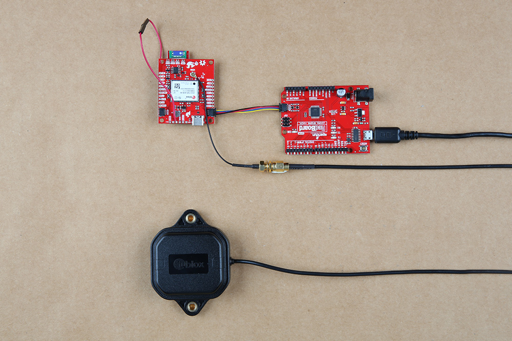
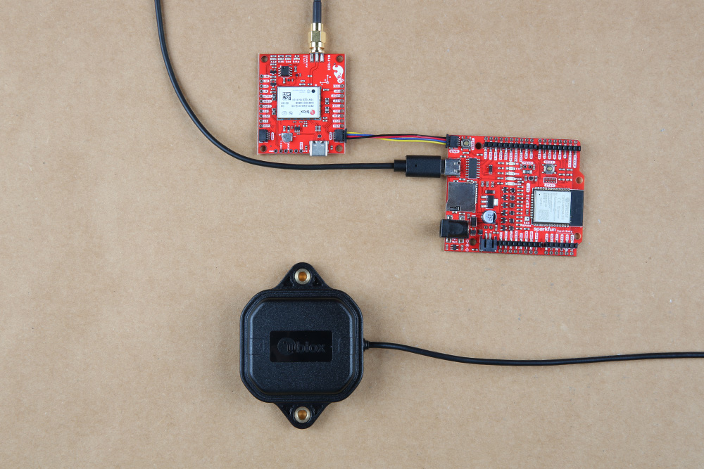
For this example, I used a RedBoard Qwiic and associated USB cable. Connecting the boards with a Qwiic cable is very simple. Plug a Qwiic cable between the RedBoard and SparkFun ZED-F9R. If you're going to be soldering to the through hole pins for I2C functionality, then just attach lines to power, ground, and the I2C data lines to a microcontroller of your choice. For users with the ZED-F9R u.FL version, you will then plug in one of our patch antennas to the u.FL connector using a u.FL to SMA cable. If you need tips on plugging in the U.FL connector, then check out our U.FL tutorial. Otherwise, you can connect the patch antenna directly to the SMA version of the board.
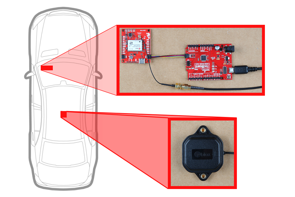
For secure connections, you may want to add tape or some hot glue to provide some strain relief to prevent the cable from disconnecting. When using the ZED-F9R, you will want to orient the board according to the guidelines explained earlier. Below is a top-down view with the board pointing up. Your setup should look similar to the image below.
 |
 |
| Connection relative to 9DOF reference axis | |
Make sure to secure the board above a vehicle's dashboard using some tape or sticky tack when prototyping and testing. For best signal reception, it is suggested to guide the antenna from the inside of the car and through a window before attaching the GPS on top of a car. We recommend the magnetic mount GPS/GNSS antenna to easily mount.
Adding a RTCM Correction Source
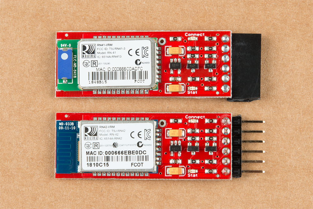
There are a few methods of adding a RTCM correction source. If you have been following along with our GPS-RTK and GPS-RTK2, you can pipe correction data from a wireless network, LoRa, or cellular network. The following example uses the Bluetooth Mate to connect to an Android phone's app. Depending on your personal preference, you can choose a female header or a male header for the Bluetooth Mate. We opted for the female header.
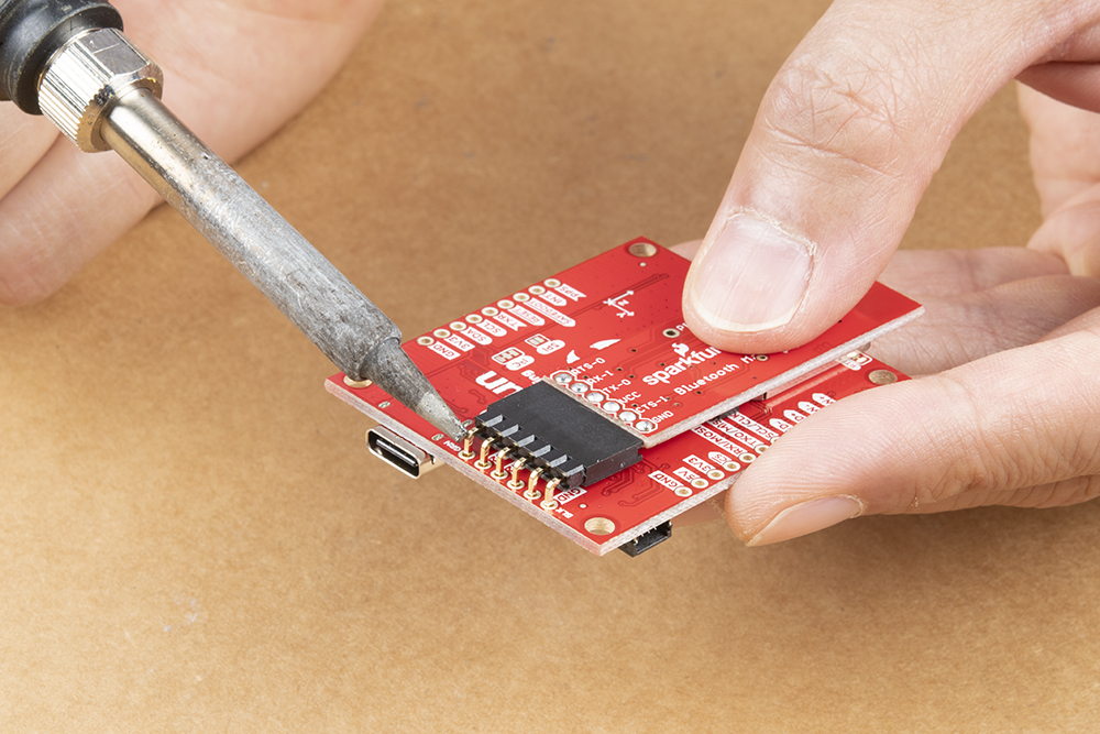
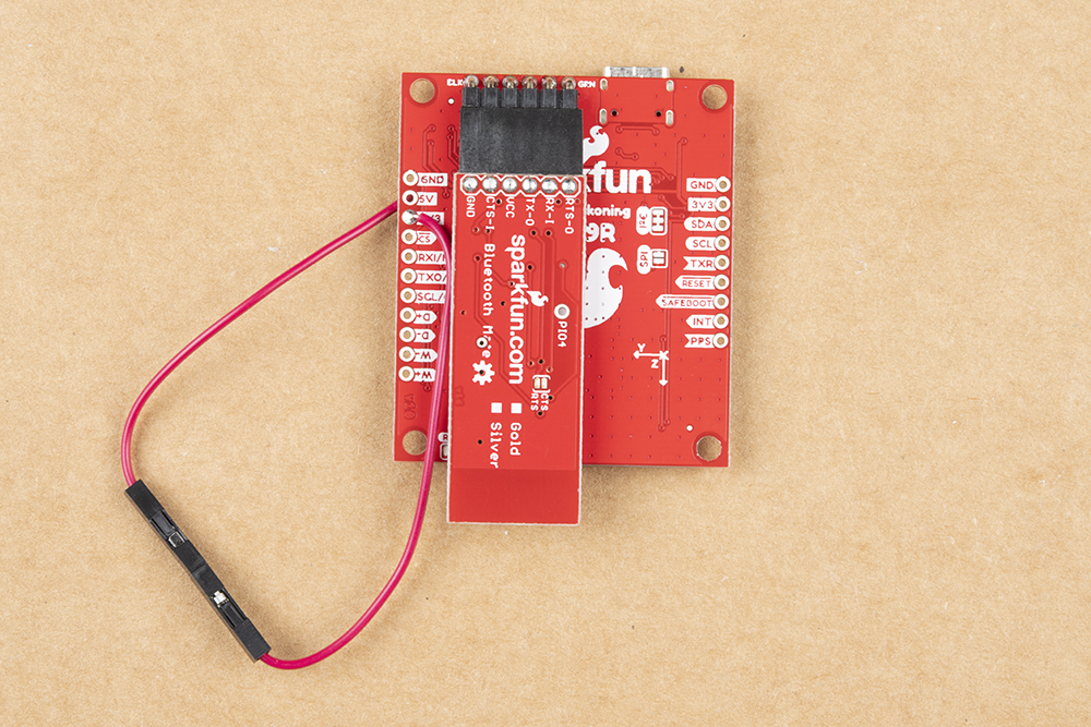
For a low profile, we decided to use 1x6 right angle, male headers. As a result, the design of the u.FL breakout v1.1 requires the top of the Bluetooth Mate to face the ZED-F9R with the u.FL version. The Bluetooth Mate will face away from the ZED-F9R for u.FL breakout v1.2 and SMA breakout v1.1. To ensure that there is enough space for the Bluetooth's components, make sure to insert the 1x6 right angle male header into the Bluetooth Mate's female header. Make sure to connect GND to GND, Rx to Tx, and Rx to Tx. When ready, solder the male headers to the breakout board.
 |
 |
| Soldering Headers on u.FL Breakout v1.1 | Soldering Headers on u.FL Breakout v1.2 |
Powering Your Correction Source
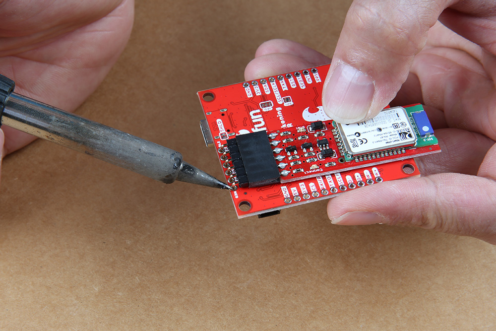
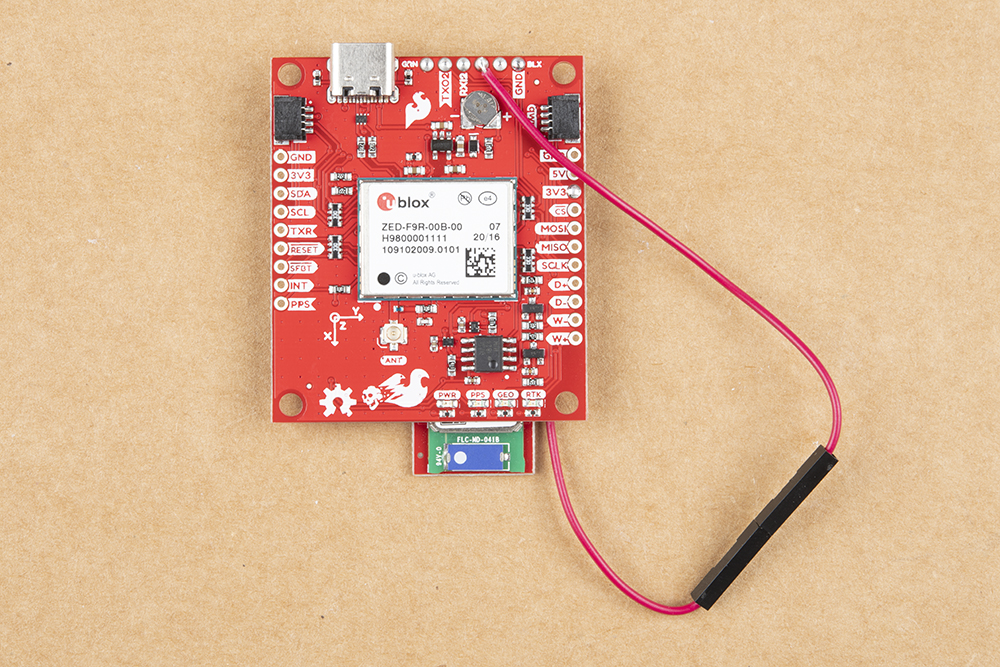
We also will need to solder a jumper wire from the 3.3V pin to the Bluetooth's VCC pin. By design, the voltage pin on the RTCM port was disconnected to avoid conflicting voltages from a device (i.e. a USB-to-Serial conveter). To easily connect/disconnect, we used a M/F jumper wire. Cut the jumper wire in half, strip, and solder the wires to the respective pins. Note that the image below uses u.FL breakout v1.1. The pins are flipped in other versions of the board.
 |
 |
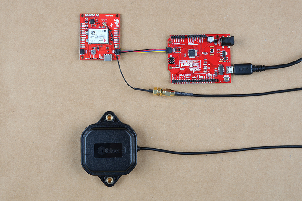
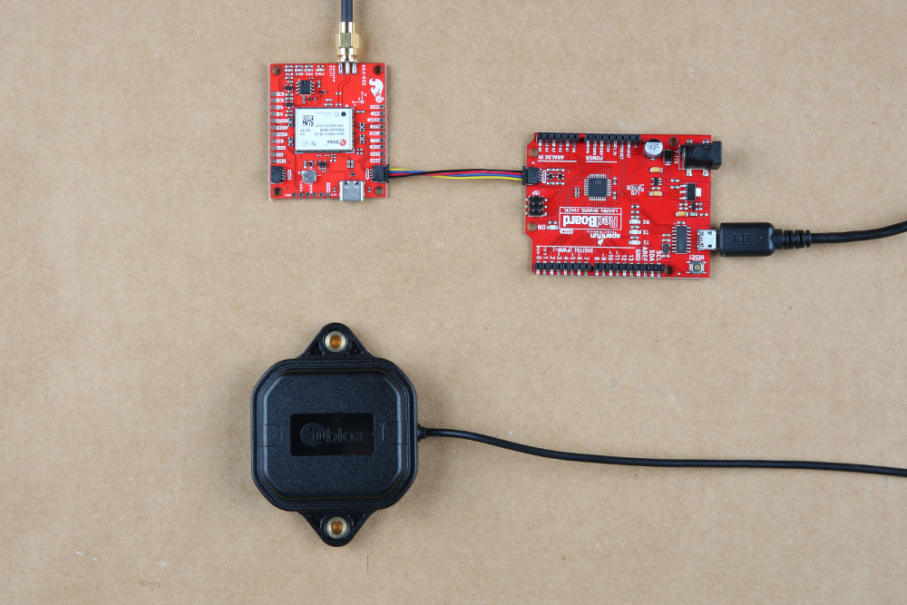
After soldering, your setup with a correction source should look like the image below. Electrical tape can be added to secure the u.FL to SMA cable to the board.