SparkFun GPS-RTK Dead Reckoning ZED-F9R Hookup Guide
 bboyho,
  Elias The Sparkiest
 Introduction
The SparkFun GPS ZED-F9R is the next iteration of u-blox's GPS offerings! This version takes advantage of dead reckoning for navigation. The u-blox ZED-F9R is a powerful GPS-RTK unit that uses a fusion of IMU, wheel ticks, a vehicle dynamics model, correction data, and GNSS measurements to provide highly accurate and continuous position for navigation in the difficult conditions. We will quickly get you set up using the Qwiic ecosystem through Arduino and Python so that you can start reading the output!
Required Materials
To follow along with this tutorial, you will need the following materials. You may not need everything though depending on what you have. The wishlist on the left is for the ZED-F9R breakout board. The wishlist on the right includes parts for the ZED-F9R pHAT. Both include parts at a minimum to get the ZED-F9R up and running. Depending on your application, you may need additional parts for a correction source or connecting to you a vehicle to obtain heel tick/direction information. Add it to your cart, read through the guide, and adjust the cart as necessary.
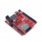
Microcontroller
If you are using the breakout board and programming in Arduino, we recommend the IoT RedBoard ESP32 with the associated USB cable to start.
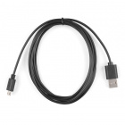

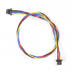
Qwiic Cable - 100mm
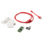
PRT-14427Single Board Computer
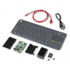
If you are using the pHAT and programming in Python, we recommend the desktop kit as it includes all the parts at a minimum to get started. Note that the Raspberry Pi 4 is power hungry so make sure that you have a sufficient power supply when using the GPS remotely. An alternative is using the Raspberry Pi Zero but it's not fast as the Raspberry Pi 4.
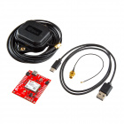
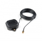
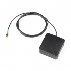
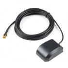
Antenna
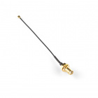
We recommend using the multi-band magnetic mount antenna for the full RF reception and mounting it on top of a vehicle. The antenna uses an SMA connector, so make sure to get the u.FL to SMA cable if you decide to use those. Link for that is below in the antenna accessories. The length of the antenna cable was also useful in mounting it.
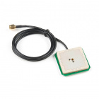
GPS Antenna Accessories
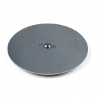
Depending on your antenna, you will need an adapter to connect to the GPS-RTK's u.FL connector. If you need more than the metal from the top of a vehicle or are mounting it on a robot that does not have the necessary ground plane, you can use the GPS antenna ground plate to improve your GPS antenna's performance.
Other Qwiic Cable Accessories
There are different Qwiic cable lengths available. Depending on your application, you can adjust it to your project's specifications.


Qwiic Cable - 50mm
PRT-14426
Qwiic Cable - 100mm
PRT-14427
Suggested Reading
If you aren't familiar with the Qwiic system, we recommend reading here for an overview.
| Qwiic Connect System |
We would also recommend taking a look at the following tutorials if you aren't familiar with them.
GPS Basics
Serial Peripheral Interface (SPI)
I2C
How to Work with Jumper Pads and PCB Traces
Getting Started with U-Center for u-blox
Three Quick Tips About Using U.FL
What is Dead Reckoning?
Dead Reckoning is the process of determining current position by combining previously determined positional data with speed and heading. This process can also be applied to determine future positions as well! The ZED-F9R uses Dead Reckoning which calculates speed and heading (amongst many other points of data) through the use of an internal inertial measurement unit (IMU). The addition of an wheel ticks, RTCM-formatted corrections, and IMU allows the ZED-F9R to produce high precision and more accurate readings in between GNSS data refreshes!
In addition, the module can also give accurate and useful GNSS data in areas where satellite connections are difficult to maintain: areas like the dense urban environments of major cities, long tunnels, parking garages, any large UFO's that may descend from the sky, etc.
Dead Reckoning Overview
As mentioned in the "What is Dead Reckoning?" section, the u-blox F9R module has an internal inertial measurement unit or IMU for short. The IMU calculates position based on the last GNSS refresh and its own movement data points. To use the SparkFun GPS-RTK Dead Reckoning Board, there are a few guidelines to orienting and mounting the module to a vehicle that are outlined from u-blox. For more detailed information, check out the integration manual for mounting.
Orientation for the SparkFun Dead Reckoning
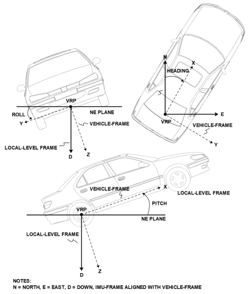
The SparkFun Dead Reckoning adheres to two particular frames of reference: one frame of reference for the car and the second a geodetic frame of reference anchoring it to the globe. The latter, known as the local level frame uses the following as its' axes:
- X-axis points to the North
- Y-axis points to the East
- Z-axis uses the right hand system by pointing down.
This frame will be referred to by its acronym NED (North-East-Down) in the image below.
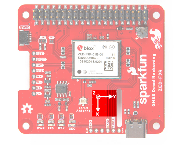
The second frame of references is the Body-Frame reference and uses the following as its' axes.
- X-axis points to the front of the vehicle
- Y-axis points to the right of the vehicle
- Z-axis uses the right hand system by pointing down.
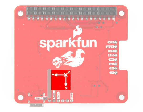
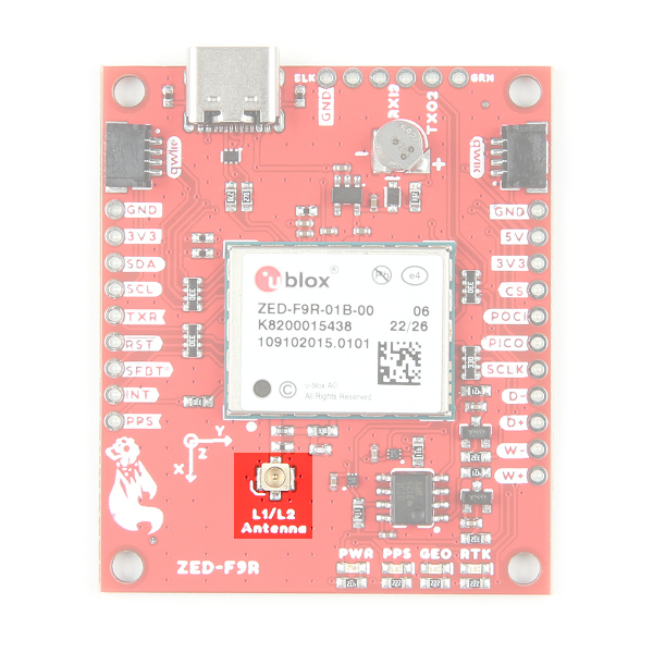
You can reference the Body-Frame axes directly on the SparkFun Dead Reckoning ZED-F9R breakout board by looking for the silkscreen with the xyz axis.
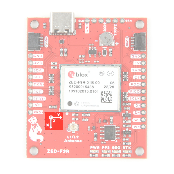 |
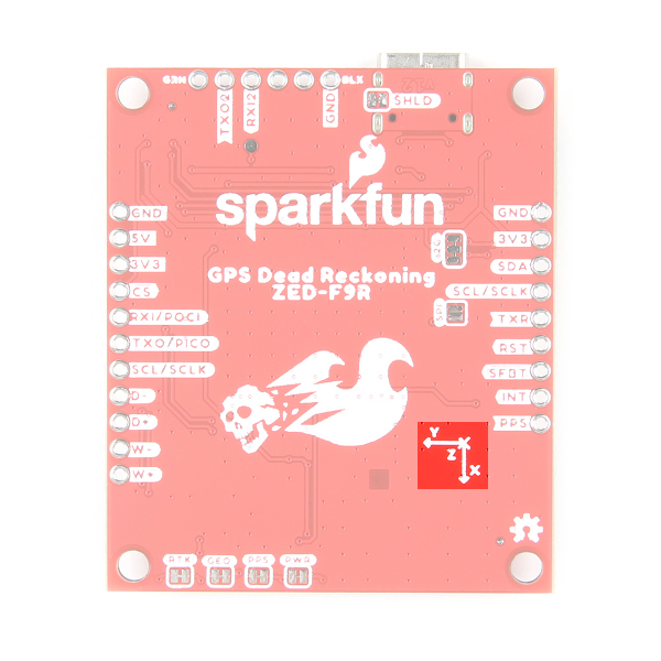 |
| Top View with the Axis for Reference | Bottom View with the Axis for Reference |
Additionally, you can find the xyz axis for reference on both sides of the pHAT.
 |
 |
| Top View with the Axis for Reference | Bottom View with the Axis for Reference |
Vehicle Attitude
The transformation of the vehicle within these two frames are given as heading, pitch, and roll. In the datasheet these three angles are called the vehicle's attitude. Below is an image that illustrates how all of these elements fit together.
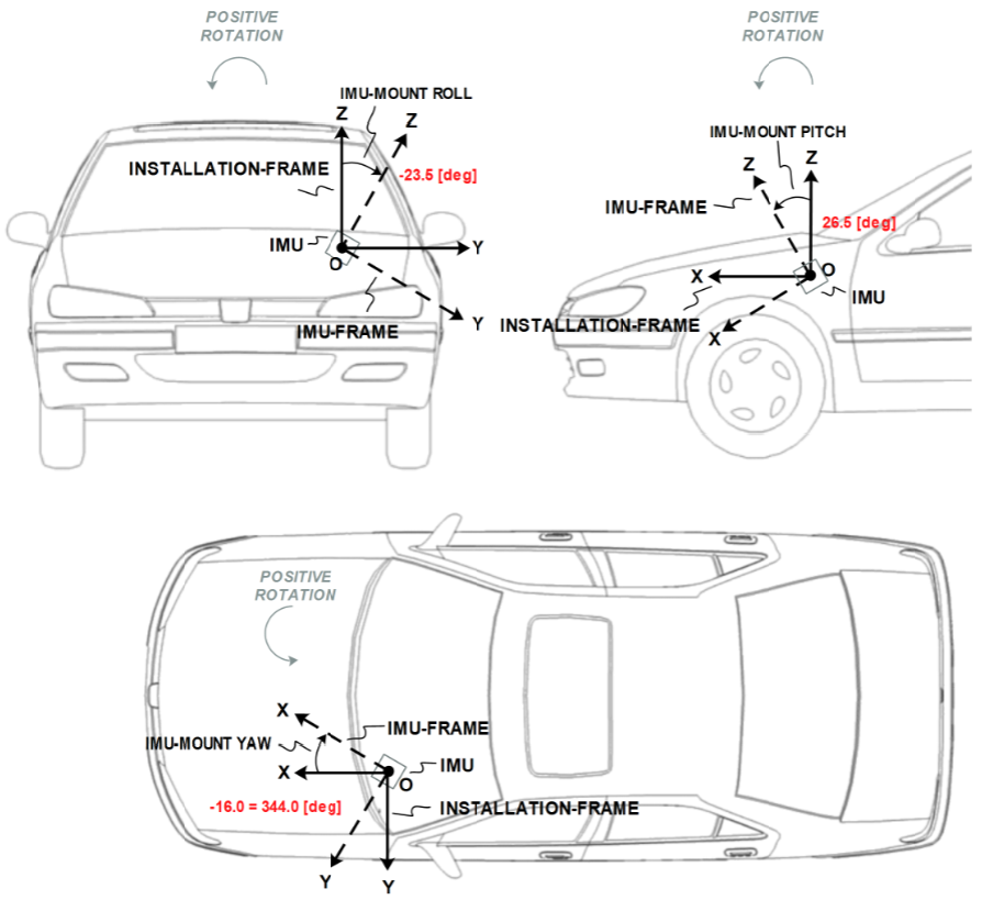
Mounting the SparkFun Dead Reckoning ZED-F9R
The only guideline here is that the SparkFun Dead Reckoning is stable within 5 degrees, and of course that the X-axis points towards the front of the car as mentioned above.
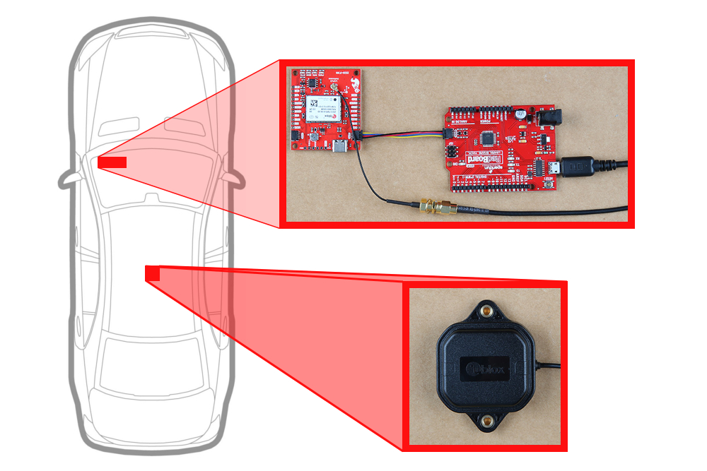
With the physical boards mounted, it will look similar to the following image.
 |
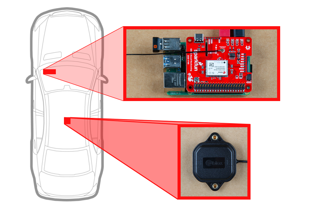 |
| ZED-F9R Orientation | ZED-F9R pHAT's Orientation |
In the image above the SparkFun Dead reckoning is seen in the front, driver's side of the car and it may be tempting to think that this is also a necessary requirement. However, it can be mounted anywhere within the vehicle (or RC-car, or boat). Keep in mind that the pitch and roll is relative to the SparkFun Dead Reckoning's position.
Calibration
After you've mounted the SparkFun Dead Reckoning ZED-F9R, there is still a calibration phase to complete that must satisfy the following movements:
- First, the car needs to be stopped with the engine turned on.
- Secondly, the car must do left and right hand turns.
- Lastly, the car must reach a speed over 30 km/h.
In SparkFun's u-blox Arduino library, SparkFun has included the calibration example, that prints out the module's calibration status.
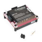
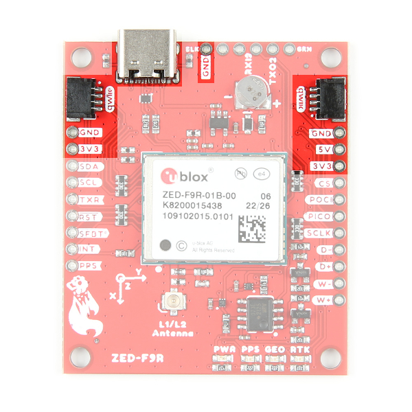
Hardware Overview (Breakout)
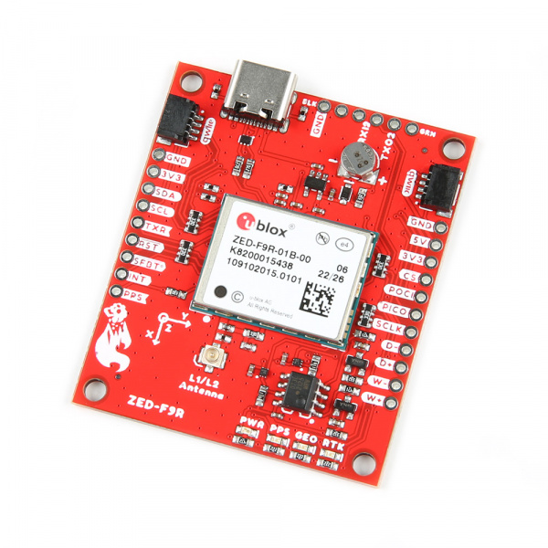
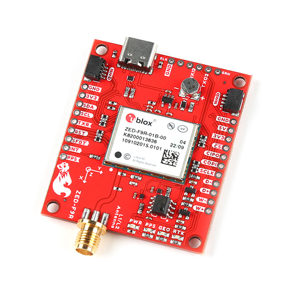
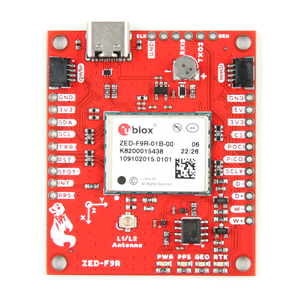
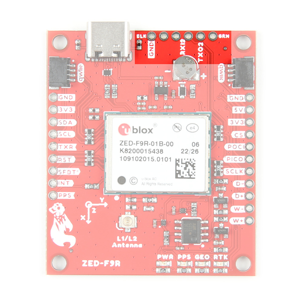
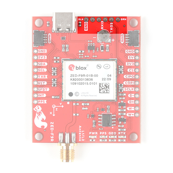
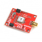
This hardware section will cover the breakout board for the GPS-RTK Dead Reckoning ZED-F9R. A majority of the images below will focus will on the u.FL version and will apply for the SMA version as well. While there are minor differences between the u.FL and SMA versions, the overall functionality of the boards is the same.
 |
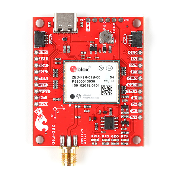 |
| ZED-F9R u.FL V1.2 | ZED-F9R SMA V1.1 |
Some of the minor differences include differences in silkscreen. You will notice this with the acronyms for SPI (MOSI vs COPI, etc.). Of course, there is also a difference in the antenna connector: u.FL vs SMA connector.
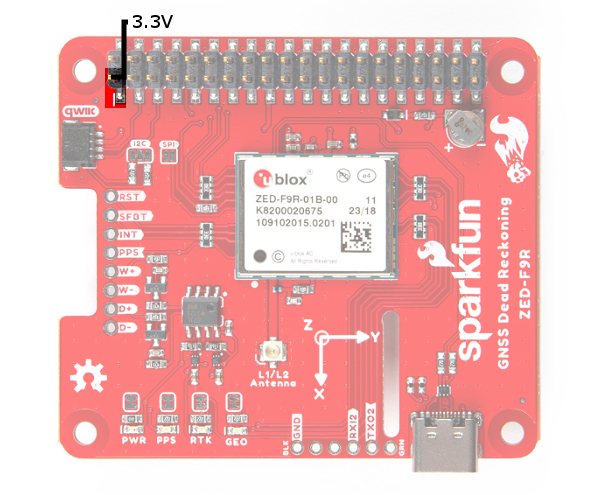
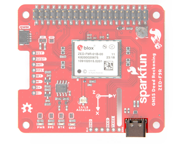
Power
Power for this board is 3.3V and we have provided multiple power options. This first and most obvious is the USB-C connector. Secondly, are the Qwiic Connectors on the left and right of the board. Thirdly, there is a 5V pin on the PTH header along the side of the board that is regulated down to 3.3V. Make sure that power you provide to this pin does not exceed 6 volts. Finally, both sides of the board includes a 3.3V pin (labeled as 3V3) that should only be provided with a clean 3.3V power signal. Of course, there is GND pins located through the board as well for reference ground.
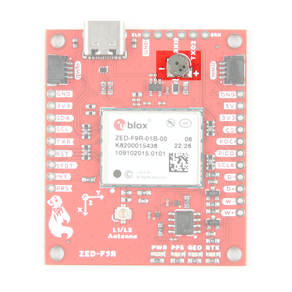
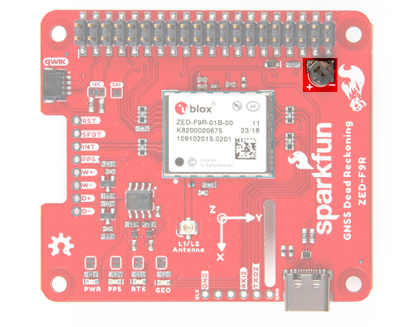
Backup Battery
The small metal disk in the upper right corner next to the Qwiic connector is a small lithium battery. This battery does not provide power to the IC like the 3.3V system does, but to relevant systems inside the IC that allow for a quick reconnection to satellites. The time to first fix will about ~26 seconds, but after it has a lock, that battery will allow for a two second time to first fix. This is known as a hot start and lasts for four hours after the board is powered down. The battery provides over a years worth of power to the backup system and charges slowly when the board is powered. To charge it to full, leave your module plugged in for 48 hours.
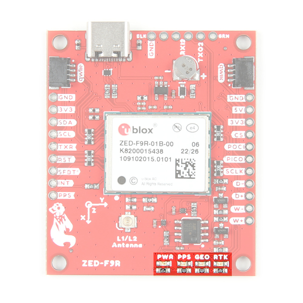
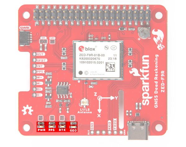
LEDs
There are four LEDs on the bottom right of the board. Starting from the left:
- PWR: The power LED labeled as
PWRwill illuminate when 3.3V is activated. - PPS: The pulse per second LED labelled as
PPSwill illuminate each second once a position lock has been achieved. This generates a pulse that is synchronized with a GPS or UTC time grid. By default, you'll see one pulse a second. - RTK: In u.FL v1.2 and SMA v1.2, the
RTKLED is turned off by default. Once RTCM data has been successfully received it will begin to blink. This is a good way to see if the ZED-F9R is getting RTCM from various sources. Once an RTK fix is obtained, the LED will turn on. However, in u.FL v1.0,RTKLED is turned on by default. The LED will be illuminated constantly upon power up. Once RTCM data has been successfully received it will begin to blink. Once an RTK fix is obtained, the LED will turn off. - GEO: The
GEOLED can be configured to turn on/off for geofencing applications.
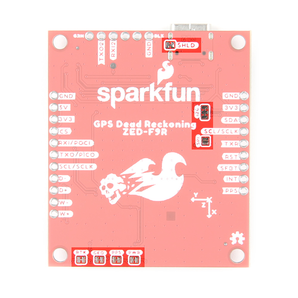
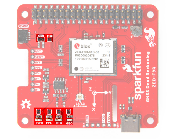
Jumpers
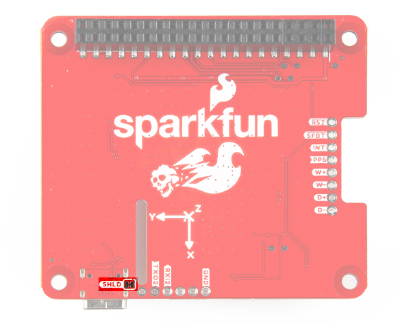
If you flip the board over, you will notice a few jumper pads. For more information on modifying the jumpers, check out our tutorial on working with jumper pads and PCB traces.
- SHLD: This jumper connects the USB Type C connector's shield pin to GND. Cut this to isolate the USB Type C connector's shield pin. This was added in the u.FL breakout v1.2 and the SMA breakout v1.1.
- I2C: This three way jumper labeled
I2Cconnects two pull-up resistors to the I2C data lines. If you have many devices on your I2C data lines, then you may consider cutting these. - SPI:The jumper labeled
SPIwhich enables the SPI data bus thus disabling the UART functions on those lines. This also disables I2C interface. - PWR: Starting from the right side is a jumper labeled
PWR. If you cut this trace, it will disconnect the Power LED. - PPS: On the left of the jumper is the
PPSjumper that when cut disconnects the PPS LED. - GEO: Cutting the
GEOjumper disconnect the LED used to indicate when we reach a certain condition for geofencing applications. - RTK: The
RTKjumper disconnects the LED used for RTK applications.
U.FL vs SMA Connector
The ZED-F9R requires a good quality multi-band GNSS antenna. For those that using the u.FL version, you will need a u.FL to SMA cable to connect to a multi-band GNSS antenna. This is useful for those that are placing the board in an enclosure. We also have a SMA version for a sturdy connection.
 |
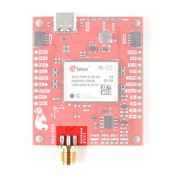 |
| ZED-F9R u.FL Connector | ZED-F9R SMA Connector |
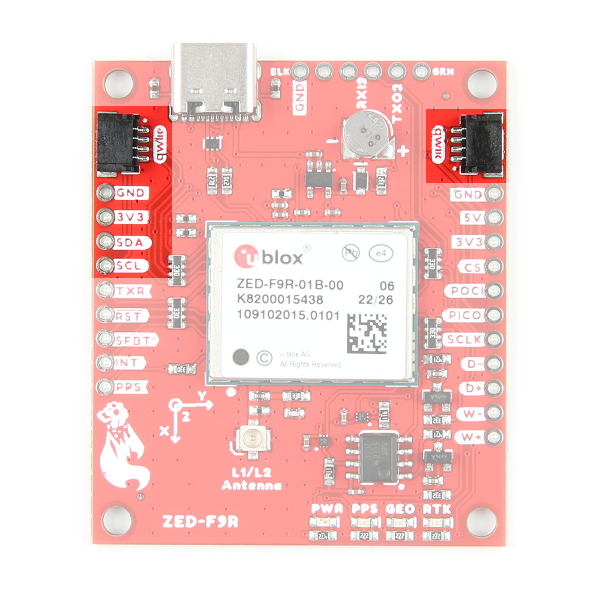
Qwiic and I2C
There are two pins labeled SDA and SCL which indicates the I2C data lines. We also conveniently added a GND and 3.3V pin should you decide to daisy chain additional I2C devices. Similarly, you can use either of the Qwiic connectors to provide power and utilize I2C. The Qwiic ecosystem is made for fast prototyping by removing the need for soldering. All you need to do is plug a Qwiic cable into the Qwiic connector and voila!
SPI
There are four pins on the right most header that are labeled with their corresponding SPI functionality. As mentioned in the jumpers section, you'll need to close the SPI jumper on the underside to enable SPI. Note that each version of the board uses different terminology for SPI. For more information, make sure to check out our SPI tutorial.
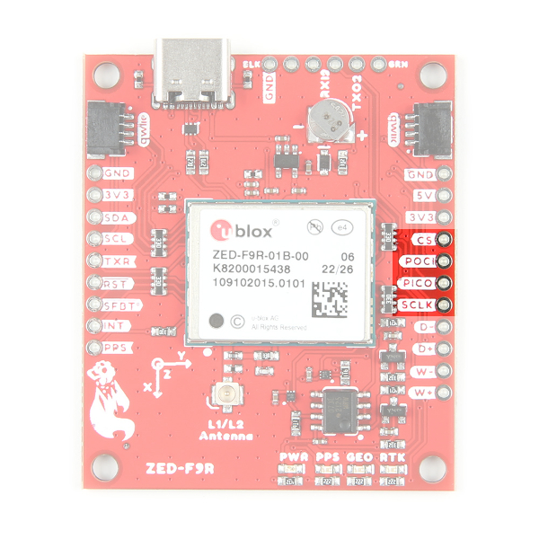 |
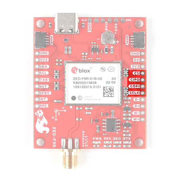 |
| SPI Pins on the u.FL and SMA Versions | |
UART1
There are two pins on the right most header currently labeled as MISO and MOSI. These are shared with the UART pins. By default, the UART interface is enabled. Be sure that the DSEL jumper on the back of the board is open.
- RX/MISO/CIPO/POCI = RX into ZED-F9R
- TX/MOSI/COPI/PICO = TX out from ZED-F9R
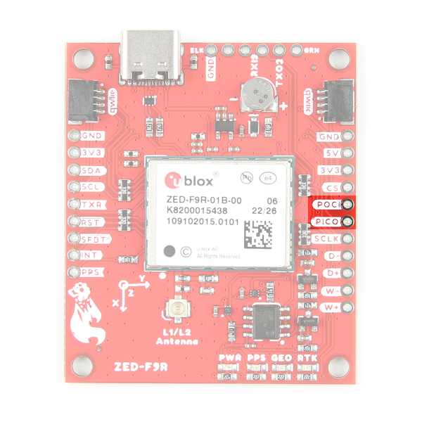 |
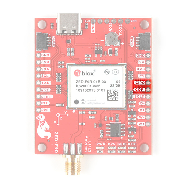 |
| UART Pins on the u.FL and SMA Versions | |
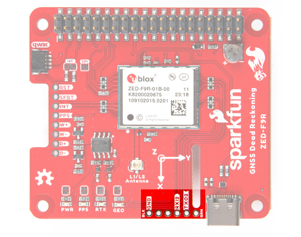
UART2
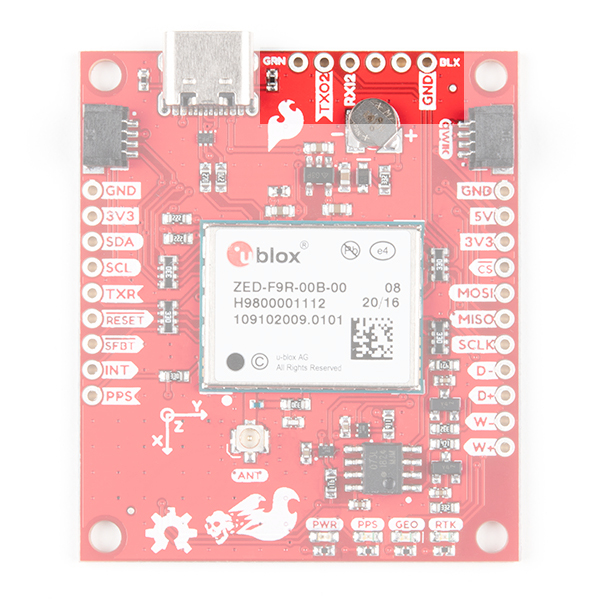
There is a second serial port available on the ZED-F9R. This is primarily used for RTCM3 correction data. By default, this port will automatically receive and parse incoming RTCM3 strings enabling RTK mode on the board like the other RTK breakout boards for the NEO-M8P-2 and ZED-F9P. The RTCM Correction port pins are arranged to match the industry standard serial connection (aka the 'FTDI' pinout). This pinout is compatible with our Bluetooth Mate and Serial Basic so you can send RTCM correction data from a cell phone or computer. Note that RTCM3 data can also be sent over I2C, UART1, SPI, or USB if desired.
 |
 |
| UART2 Port on u.FL Version | UART2 Port on SMA Version |
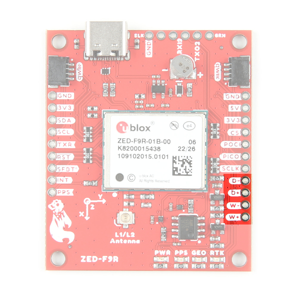
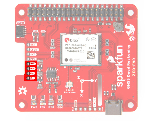
Wheel Tick and Direction Pins
For advanced users that are interested in taking advantage of your vehicle's sensor readings, you can connect the following pins. Caution is advised however as this requires you to open up the hood of your car and hack into the its system.
- D-: The reference GND pin (
D-) when connecting the direction pin. - D+: The direction pin is labeled as (
D+) tells the ZED-F9R what direction the vehicle is moving (forward/reverse). - W-: The reference GND pin (
W-) when connecting the wheel tick pin. - W+: The wheel tick pin (
W+) tells the ZED-F9R the distance a vehicle's wheel has traveled. Depending on the odometer type that you connect to, the ZED-F9R can also receive speed data from the vehicle.
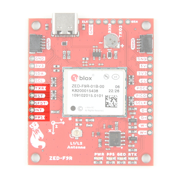
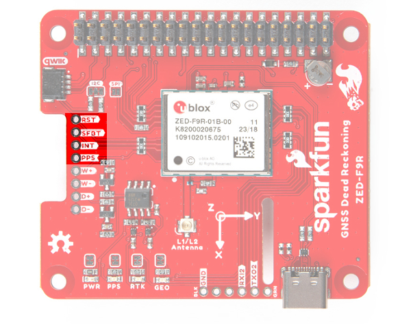
Broken Out Pins
There are five other pins broken out:
- TXR: The transmit ready pin (
TXR) enables a port to notify a device when bytes are ready to be transmitted. - RESET: The reset pin (
RESET) resets the chip. - SFBT: The safeboot pin (
SFBT) is used to start up the IC in safe boot mode, this could be useful if you somehow manage to corrupt the module's Flash memory. - INT: The interrupt pin (
INT) can be used to wake the chip from power save mode. - PPS: The pulse per second pin (
PPS) outputs pulse trains synchronized with the GPS or UTC time grid. The signal defaults to once per second but is configurable over a wide range. Read the u-blox Receiver Protocol Specification in the Resources and Going Further tab for more information.
3D IMU Orientation and Reference
For easy reference, we've documented the IMU's vectors with 3D Cartesian coordinate axes on the top and bottom side of the board. Make sure to orient and mount the board correctly so that the ZED-F9R can accurately calculate navigation information. Remember, it's all relative.
|
|
| 9DoF Reference (Top View) | 9DoF Reference (Bottom View) |
GPS Capabilities
The ZED-F9R is able to connect to up to four different GNSS constellations simultaneously with the 3D gyro and 3D accelerometer making it very accurate for its size. Below are the listed capabilities of the GPS unit.
| Parameter | Specification | |
|---|---|---|
| Max navigation update rate (RTK) | Priority navigation mode | 30 Hz |
| Non-Priority navigation mode | 2 Hz | |
| Velocity Accuracy | 0.05m/s | |
| Dynamic Attitude Accuracy | Heading | 0.2 degrees |
| Pitch | 0.3 degrees | |
| Roll | 0.5 degrees | |
| Navigation Latency | Priority Navigation Mode | 15ms |
| Max Sensor Output Rate | 100Hz | |
| GNSS | GPS+GLO+GAL +BDS | GPS+GLO+GAL | GPS+GAL | GPS+GLO | BDS+GLO | |
|---|---|---|---|---|---|---|
| Time-To-First-Fix | Cold Start | 26s | 25s | 30s | 25s | 28s |
| Hot Start | 2s | 2s | 2s | 2s | 2s | |
| Aided Start | 3s | 3s | 3s | 3s | 3s | |
| Re-convergence time | RTK | ≤ 10s | ≤ 10s | ≤ 10s | ≤ 10s | ≤ 30s |
| Sensitivity | Tracking and Navigation | -160dBm | -160dBm | -160dBm | -160dBm | -160dBm |
| Reacquisition | -157dBm | -157dBm | -157dBm | -157dBm | -157dBm | |
| Cold Start | -147dBm | -147dBm | -147dBm | -147dBm | -145dBm | |
| Hot Start | -158dBm | -158dBm | -158dBm | -158dBm | -158dBm |
| Horizontal Position Accuracy | PVT | 1.5m CEP | 1.5m CEP | 1.5m CEP | 1.5m CEP | 1.5m CEP |
| SBAS | 1.0m CEP | 1.0m CEP | 1.0m CEP | 1.0m CEP | 1.0m CEP | |
| RTK | 0.01m + 1ppm CEP | 0.01m + 1ppm CEP | 0.01m + 1ppm CEP | 0.01m + 1ppm CEP | 0.01m + 1ppm CEP |
|
| Vertical Position Accuracy | RTK | 0.01m +1ppm R50 | 0.01m +1ppm R50 | 0.01m +1ppm R50 | 0.01m +1ppm R50 | 0.01m +1ppm R50 |
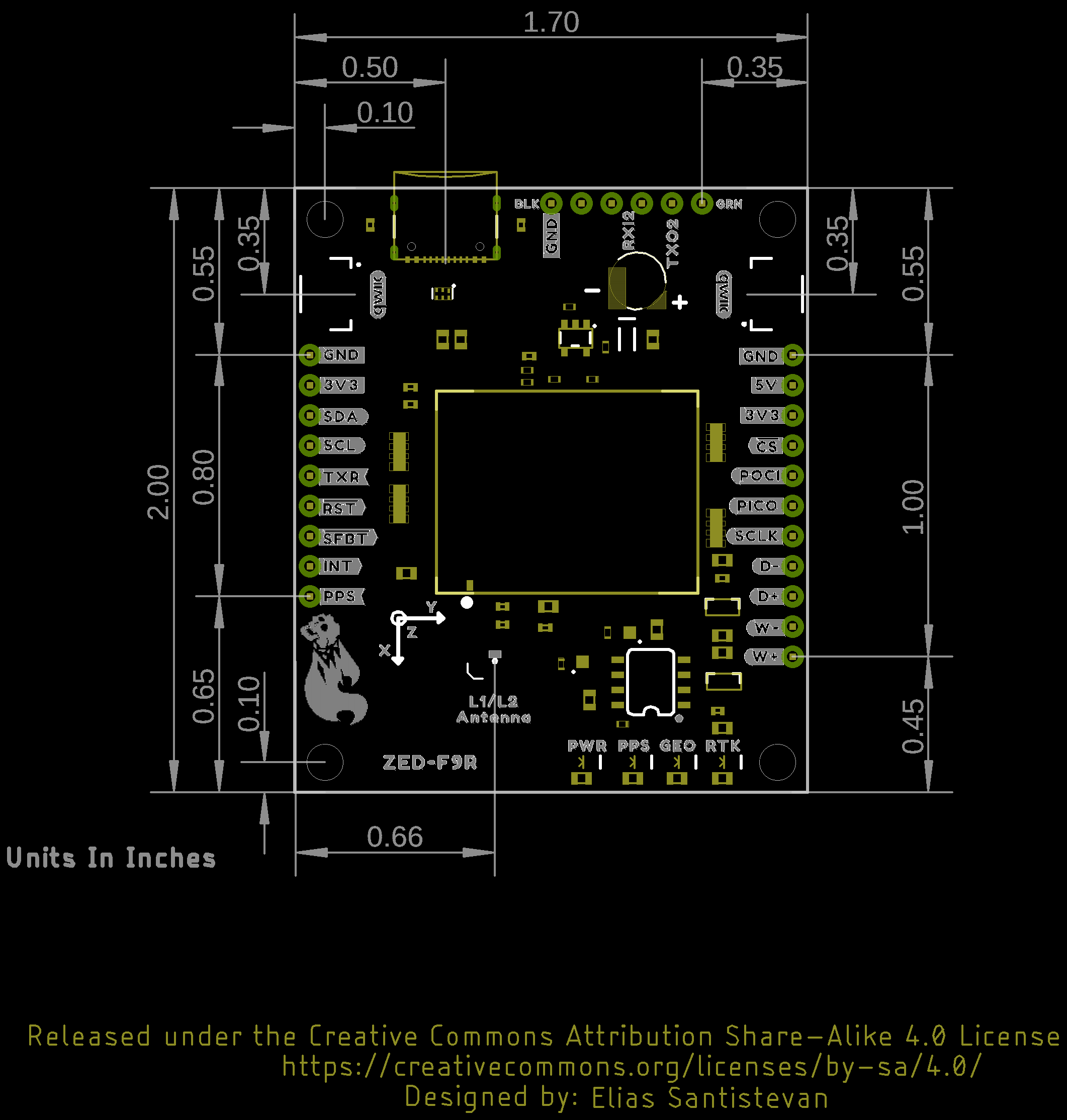
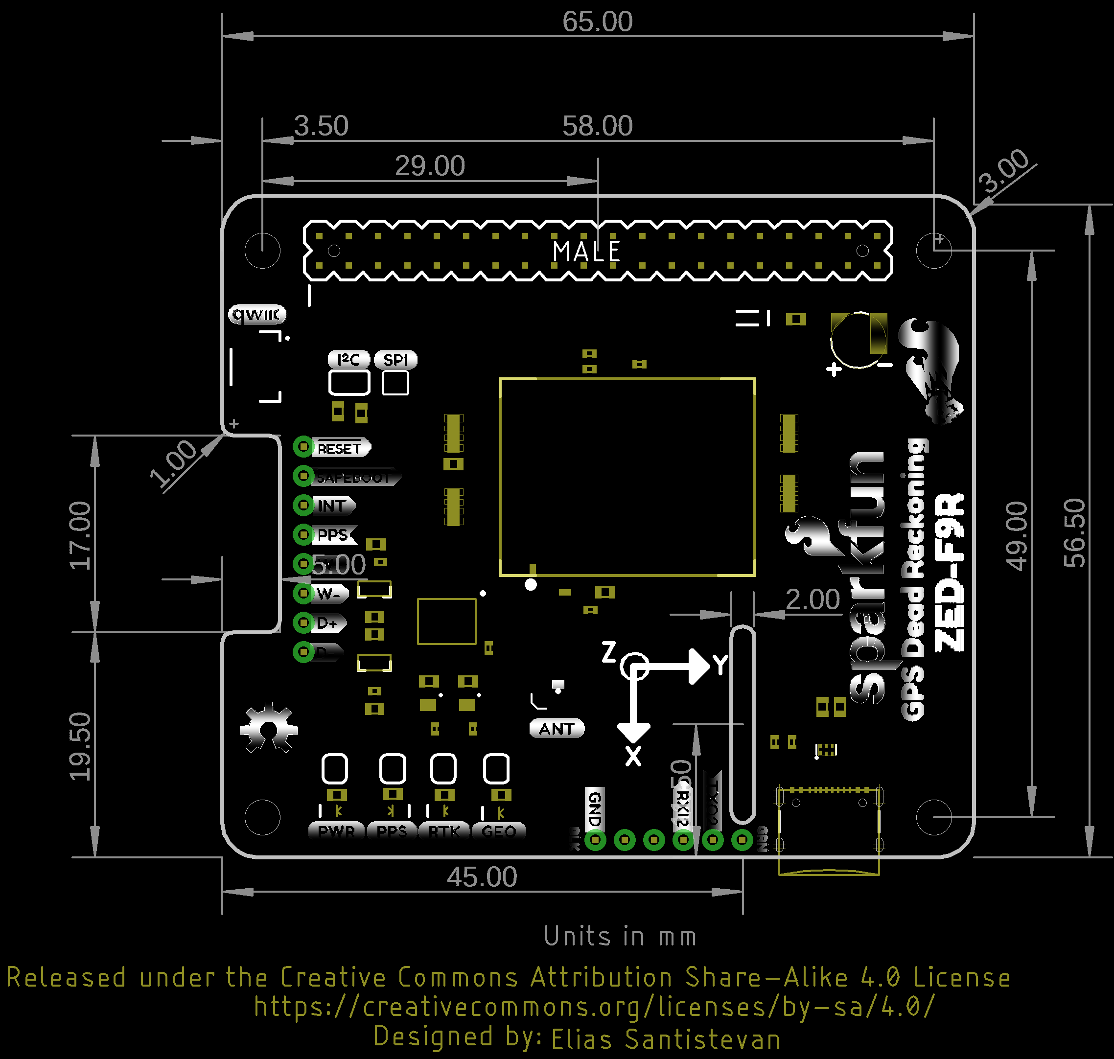
Board Dimensions
Overall, both versions of the breakout board is 2.00"x1.70". There are 4x mounting holes by each corner of the board. Note that the SMA connector increases the length of the board slightly and you will need to attach a GNSS antenna to that connector as well.
 |
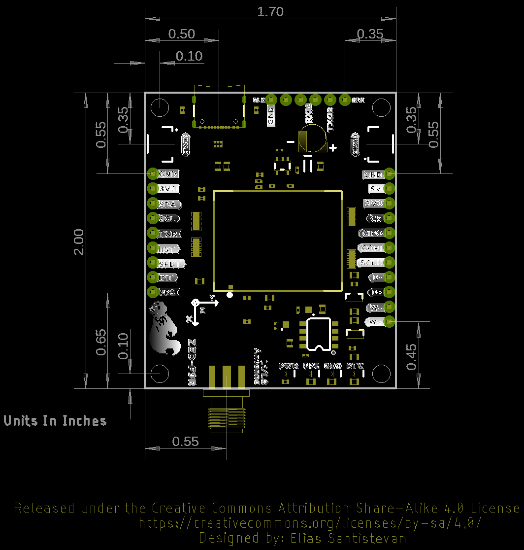 |
| Board Dimensions for u.FL version | Board Dimensions for SMA version |
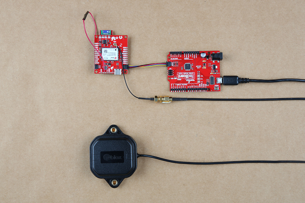
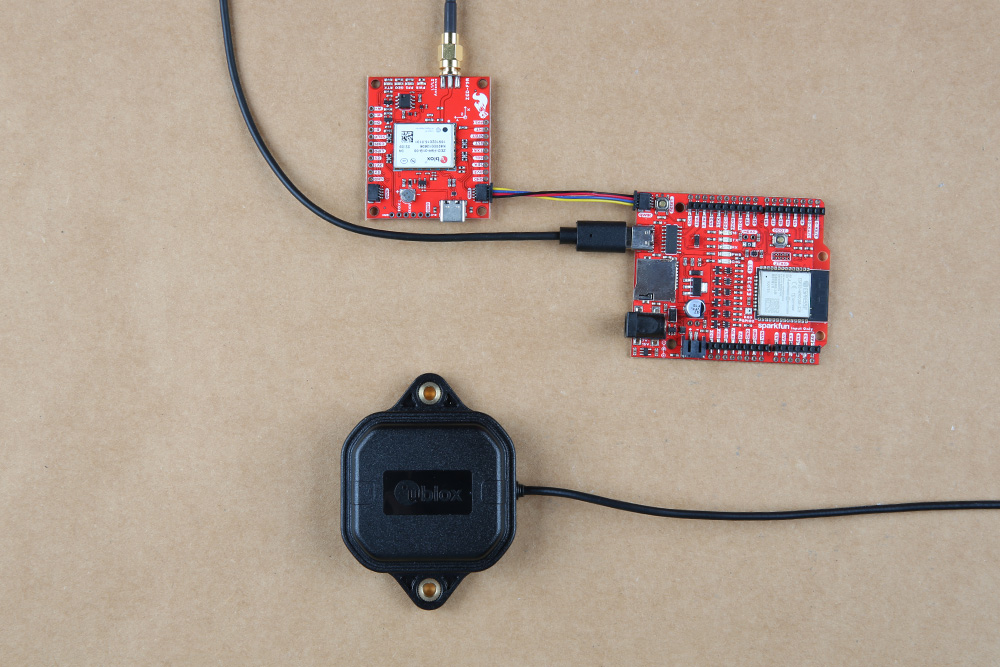
Hardware Assembly (Breakout)
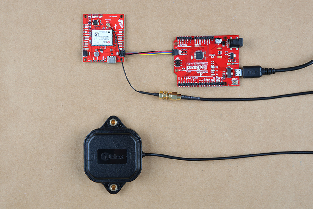
For this example, I used a RedBoard Qwiic and associated USB cable. Connecting the boards with a Qwiic cable is very simple. Plug a Qwiic cable between the RedBoard and SparkFun ZED-F9R. If you're going to be soldering to the through hole pins for I2C functionality, then just attach lines to power, ground, and the I2C data lines to a microcontroller of your choice. For users with the ZED-F9R u.FL version, you will then plug in one of our patch antennas to the u.FL connector using a u.FL to SMA cable. If you need tips on plugging in the U.FL connector, then check out our U.FL tutorial. Otherwise, you can connect the patch antenna directly to the SMA version of the board.
For secure connections, you may want to add tape or some hot glue to provide some strain relief to prevent the cable from disconnecting. When using the ZED-F9R, you will want to orient the board according to the guidelines explained earlier. Below is a top-down view with the board pointing up. Your setup should look similar to the image below.
 |
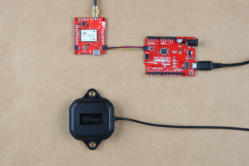 |
| Connection relative to 9DOF reference axis | |
Make sure to secure the board above a vehicle's dashboard using some tape or sticky tack when prototyping and testing. For best signal reception, it is suggested to guide the antenna from the inside of the car and through a window before attaching the GPS on top of a car. We recommend the magnetic mount GPS/GNSS antenna to easily mount.
Adding a RTCM Correction Source
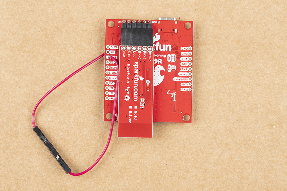
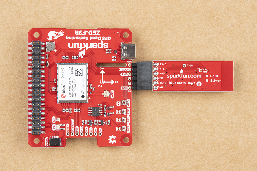
There are a few methods of adding a RTCM correction source. If you have been following along with our GPS-RTK and GPS-RTK2, you can pipe correction data from a wireless network, LoRa, or cellular network. The following example uses the Bluetooth Mate to connect to an Android phone's app. Depending on your personal preference, you can choose a female header or a male header for the Bluetooth Mate. We opted for the female header.
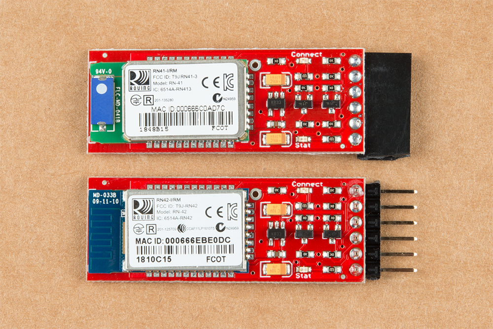
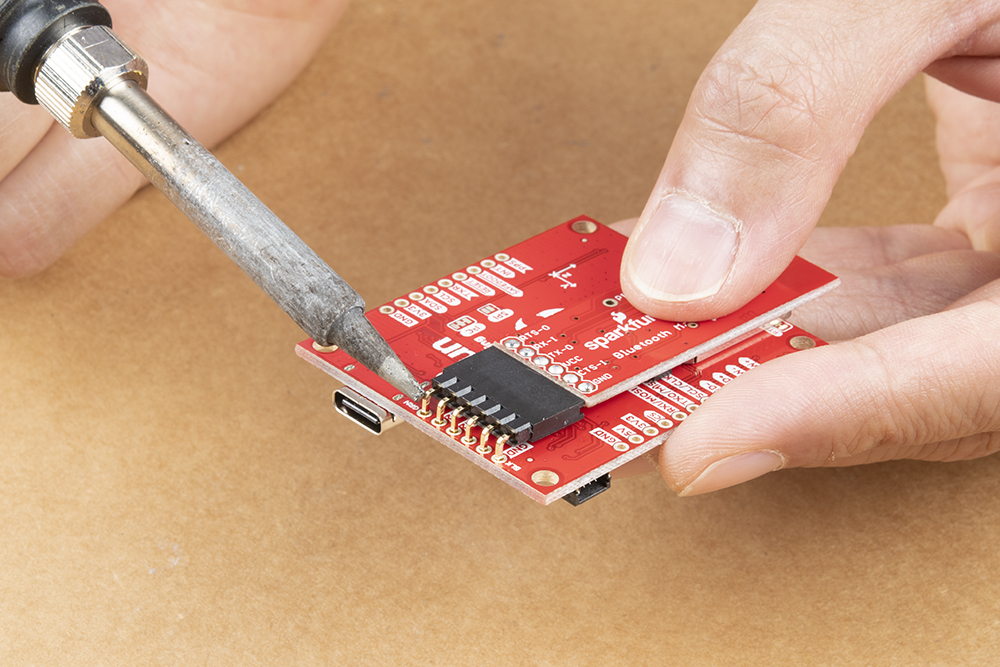
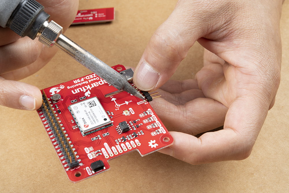
For a low profile, we decided to use 1x6 right angle, male headers. As a result, the design of the u.FL breakout v1.1 requires the top of the Bluetooth Mate to face the ZED-F9R with the u.FL version. The Bluetooth Mate will face away from the ZED-F9R for u.FL breakout v1.2 and SMA breakout v1.1. To ensure that there is enough space for the Bluetooth's components, make sure to insert the 1x6 right angle male header into the Bluetooth Mate's female header. Make sure to connect GND to GND, Rx to Tx, and Rx to Tx. When ready, solder the male headers to the breakout board.
 |
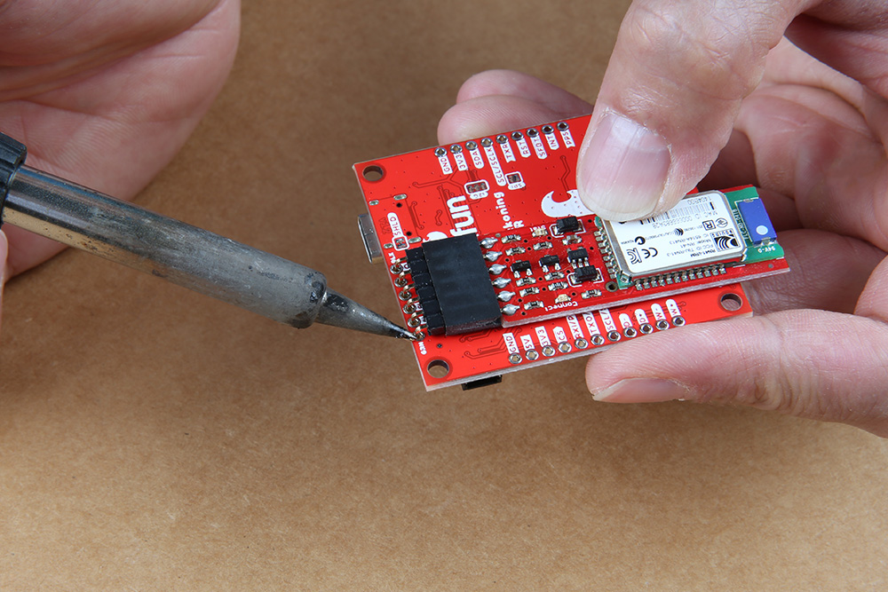 |
| Soldering Headers on u.FL Breakout v1.1 | Soldering Headers on u.FL Breakout v1.2 |
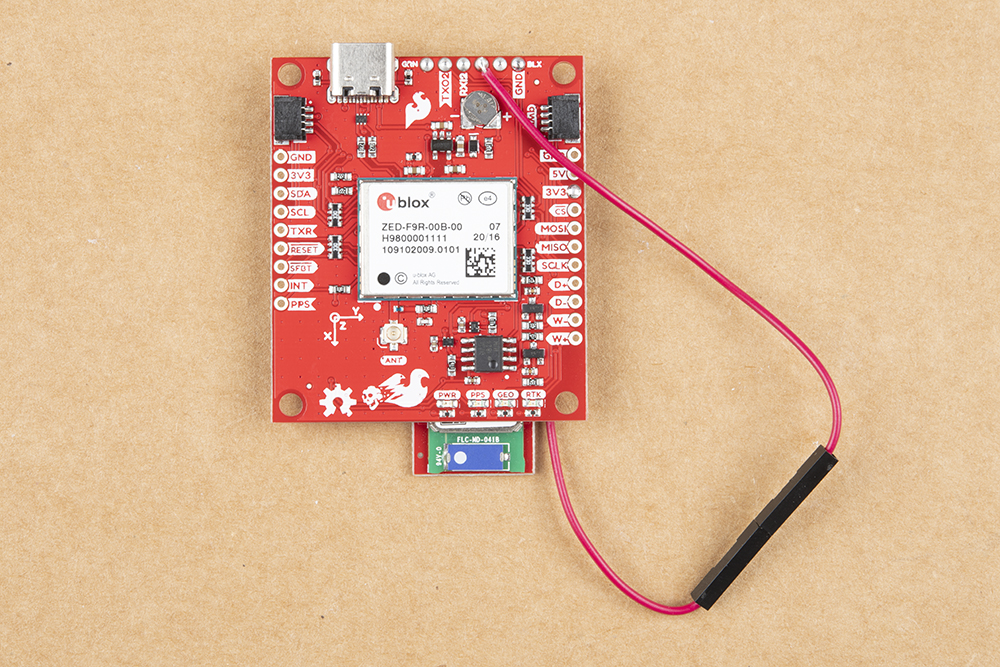
Powering Your Correction Source
We also will need to solder a jumper wire from the 3.3V pin to the Bluetooth's VCC pin. By design, the voltage pin on the RTCM port was disconnected to avoid conflicting voltages from a device (i.e. a USB-to-Serial conveter). To easily connect/disconnect, we used a M/F jumper wire. Cut the jumper wire in half, strip, and solder the wires to the respective pins. Note that the image below uses u.FL breakout v1.1. The pins are flipped in other versions of the board.
 |
 |
After soldering, your setup with a correction source should look like the image below. Electrical tape can be added to secure the u.FL to SMA cable to the board.
SparkFun u-blox Arduino Library
VALSET and VALGET) to configure the module, instead of the deprecated UBX-CFG messages. For modules like the F9 and M10, we recommend upgrading to Version 3. However, older modules like the M8 do not support the Configuration Interface. For those you will need to keep using Version 2 of the library. We will continue to support both.
The SparkFun u-blox Arduino library can be downloaded with the Arduino library manager by searching 'SparkFun u-blox GNSS v3' or you can grab the zip here from the GitHub repository to manually install. Once calibrated, you can take advantage of the examples for the ZED-F9R.
There are example sketches provided to get you up and receiving messages from space. The examples listed below highlight the additional capabilities of the SparkFun Dead Reckoning ZED-F9R. For the scope of this tutorial, we will not focus on the basic GPS polling sketches as shown in the other u-blox hookup guides.
Arduino Example Code
Example 1 - Calibrate Sensor
Now that the GPS-RTK SparkFun Dead Reckoning is mounted and oriented correctly with regards to the vehicle, it's time to calibrate the sensor. To do this, a few movements with the vehicle must be done all while maintaining good GNSS reception.
- First, the car needs to be stopped with the engine turned on.
- Secondly, the car must do left and right hand turns.
- Lastly, the car must reach a speed over 30 km/h.
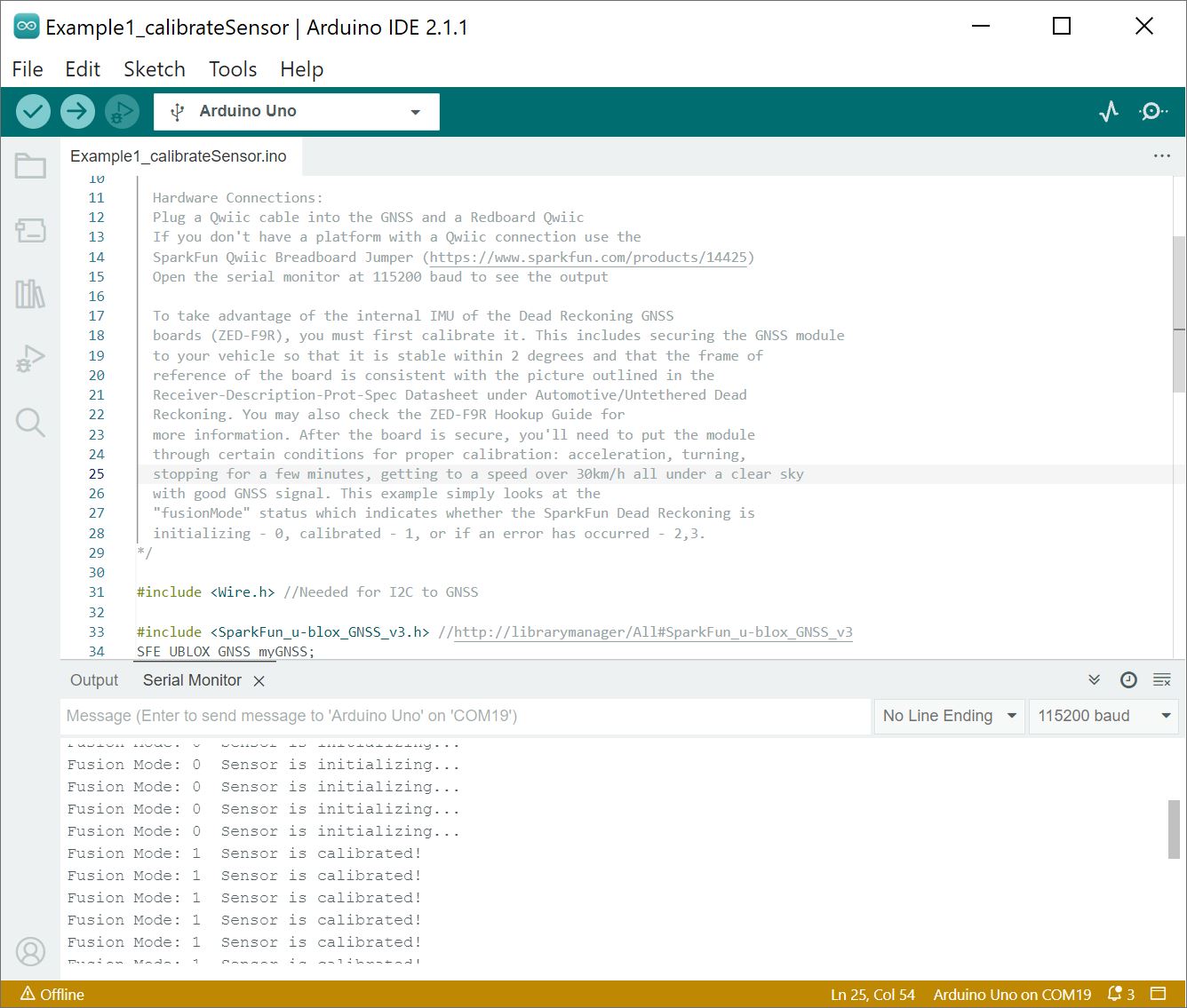
For the first example (located in File Examples > SparkFun u-blox GNSS Arduino Library > Dead Reckoning > Example1_calibrateSensor), the calibration status will be printed to the Arduino's serial monitor to indicate when calibration is ongoing and when it has completed.
If you have not already, select your Board (in this case the Arduino Uno), and associated COM port. Upload the code to the board and and set the serial monitor to 115200 baud. Perform those fancy maneuvers (while obeying the traffic laws) before parking your car in a safe location. Then turn your engine off before checking the status!
You should see a message indicating that the ZED-F9R's sensor is calibrated (e.g. Fusion Mode: 1 Sensor is calibrated!). If you do not, try driving around with the board once again!
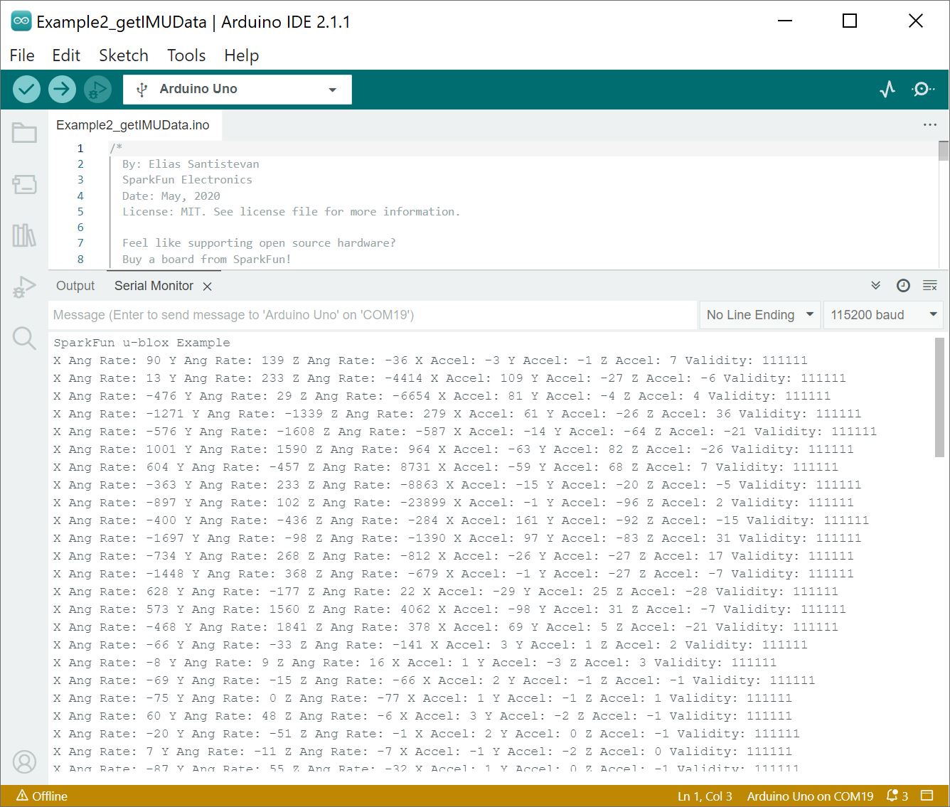
Example 2 - IMU Data
After you have your sensor calibrated (see example1), you can now poll the internal IMU to see what data is being fed to the GNSS calculations. Open the second example (located in File Examples > SparkFun u-blox GNSS Arduino Library > Dead Reckoning > Example2_getIMUData) to follow along! First, the sketch checks to see that the board is calibrated before it attempts to read IMU data.
If you have not already, select your Board (in this case the Arduino Uno), and associated COM port. Upload the code to the board and set the serial monitor to 115200 baud. This may be a good time to bring a friend along to drive if you decide to actively monitor the output. Otherwise, check out the data after taking the board for a stroll. Try driving around as the board senses the car's movement. Then park in a safe location with the engine turned off before inspecting the data.
Below is an example output shows the ZED-F9R mounted on a car that was initially parked on the side of a neighborhood. We took it for a stroll by accelerating, decelerating, turning around, accelerating again in the other direction, decelerating, and parking again.
Try grabbing a DataLogger or a microcontroller with a built-in microSD card. Then adjust the code to output the sensor data as CSV with timestampes and saving them to a memory card. Once the data is imported into a spreadsheet, try graphing the values to visualize the readings.
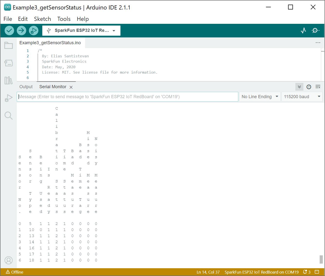
Example 3 - Get Sensor Status
This example is used primarily as a diagnostic sketch. What sensors are currently being used, are they functioning correctly, are the measurements being listed as bad or non-existent? Example 3 helps diagnose these various issues. Open the third example in the library (located in File Examples > SparkFun u-blox GNSS Arduino Library > Dead Reckoning > Example3_getSensorStatus).
If you have not already, select your Board (in this case the ESP32 IoT RedBoard), and associated COM port. Upload the code to the board and set the serial monitor to 115200 baud. Below is an example output after getting the sensor status. To decipher the readings, we recommend checking out the u-blox ZED-F9R's receiver interface description on page 71 under the section labeled "3.11.5.1 External sensor fusion status" for more information.
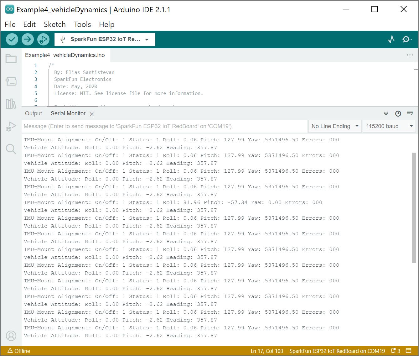
Example 4 - Vehicle Dynamics
The vehicle attitude is a termed coined by u-blox that encompasses three measurements: vehicle pitch, vehicle roll, and vehicle heading. Much like the other example sketches, this one checks to make sure that the SparkFun Dead Reckoning ZED-F9R has been calibrated before pulling data. If the SparkFun Dead Reckoning ZED-F9R has indeed been calibrated, then it gets the relevant information by calling myGNSS.getVehAtt(). As in Example 2, the data is stored within a struct called vehAtt. Open the fourth example in the library (located in File Examples > SparkFun u-blox GNSS Arduino Library > Dead Reckoning > Example4_vehicleDynamics).
If you have not already, select your Board (in this case the ESP32 IoT RedBoard), and associated COM port. Upload the code to the board and set the serial monitor to 115200 baud. This may be a good time to bring a friend along to drive if you decide to actively monitor the output. Otherwise, check out the data after taking the board for a stroll. Try driving around as the board senses the car's movement. Then park in a safe location with the engine turned off before inspecting the data. Below is an example output of the vehicle dynamics with the car parked.
ZED-F9P Example Folder
Once the ZED-F9R is calibrated, you will be able to use a few of the ZED-F9P examples. Note that the ZED-F9R is not able to act as a base station so a few of the examples may not apply. You'll also need to feed RTCM correction data to the ZED-F9R if you decide to utilize the RTK feature. For more information, check below.
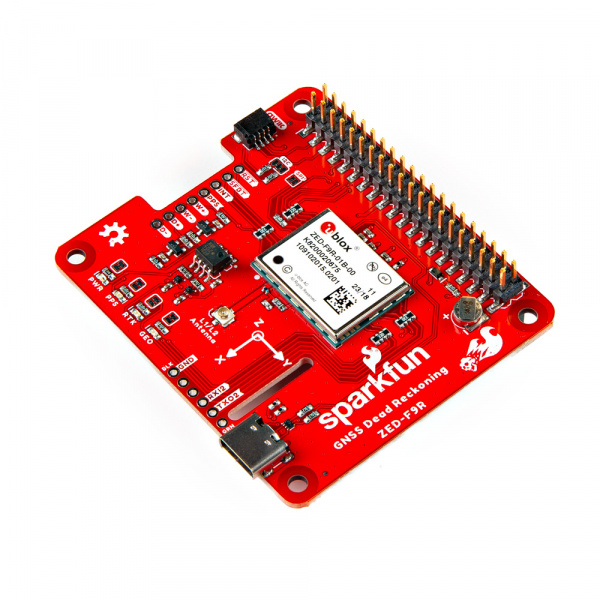
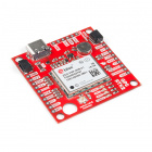
Hardware Overview (pHAT)
Power
Power for this board is 3.3V. Unlike the breakout board, the pHAT version pulls power from the Raspberry Pi's 3.3V pin on the 2x20 header. The Qwiic Connector's voltage pin is connected to this rail. The 3.3V pin should only be provided a clean 3.3V power signal from the Pi.
Backup Battery
Just like the breakout board, the small metal disk in the just to the right of the ZED-F9R module is a small lithium battery. This battery does not provide power to the IC like the 3.3V system does, but to relevant systems inside the IC that allow for a quick reconnection to satellites. The time to first fix will about ~26 seconds, but after it has a lock, that battery will allow for a two second time to first fix. This is known as a hot start and lasts for four hours after the board is powered down. The battery provides over a years worth of power to the backup system and charges slowly when the board is powered. To charge it to full, leave your module plugged in for 48 hours.
LEDs
Just like the breakout board, there are four LEDs on the bottom left of the board. Starting from the left:
- PWR: The power LED labeled as
PWRwill illuminate when 3.3V is activated. - PPS: The pulse per second LED labelled as
PPSwill illuminate each second once a position lock has been achieved. This generates a pulse that is synchronized with a GPS or UTC time grid. By default, you'll see one pulse a second. - RTK: The
RTKLED will be illuminated constantly upon power up. Once RTCM data has been successfully received it will begin to blink. This is a good way to see if the ZED-F9R is getting RTCM from various sources. Once an RTK fix is obtained, the LED will turn off. - GEO: The
GEOLED can be configured to turn on/off for geofencing applications.
Jumpers
On the top side of the board, you will notice a few jumper pads.
- I2C: This three way jumper labeled
I2Cconnects two pull-up resistors to the I2C data lines. For general use, you can leave this jumper unmodified. If you have many I2C devices (about 7x devices, each with their own pull-up resistors), you will need to cut the jumpers. - SPI: The jumper labeled
SPIis open by default. Closing the jumper with solder enables the SPI data bus thus disabling the UART functions on those lines. This also disables I2C interface. USB will still function. - PWR: Starting from the right side is a jumper labeled
PWR. If you cut this trace, it will disconnect the Power LED. - PPS: On the left of the jumper is the
PPSjumper that when cut disconnects the PPS LED. - GEO: Cutting the
GEOjumper disconnect the LED used to indicate when we reach a certain condition for geofencing applications. - RTK: The
RTKjumper disconnects the LED used for RTK applications. - SHLD: On the back of the board, the
SHLDjumper connects the USB Type C connector's shield pin to GND. Cut this to isolate the USB Type C connector's shield pin. This was added in v1.1.
For more information, check out our tutorial on How to Work with Jumper Pads and PCB Traces .
 |
 |
U.FL Connector
The ZED-F9R requires a good quality L1/L2 GPS or GNSS (preferred) antenna. A U.FL connector is provided. Note: U.FL connectors are rated for only a few mating cycles (about 30) so we recommend you set it and forget it. You may need to secure the u.FL to SMA cable depending on your application. For more information on working with u.FL connectors, we recommend checking out our tutorial about using u.FL connectors.
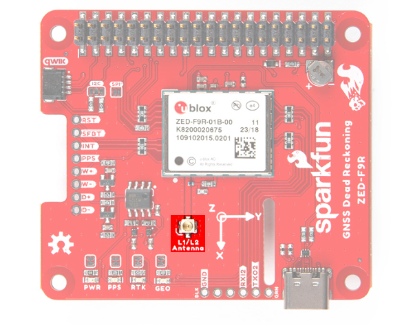
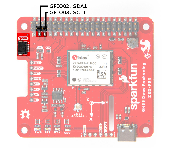
Qwiic and I2C
After stacking the pHAT on a Raspberry Pi, you still have access to the I2C pins (GPIO02 and GPIO03) on the top side. Alternatively, you can use the Qwiic connector to daisy chain additional I2C devices on the bus. The Qwiic ecosystem is made for fast prototyping by removing the need for soldering. All you need to do to connect additional Qwiic devices is plug a Qwiic cable into the Qwiic connector and voila! You can also access those pins from the 2x20 header.
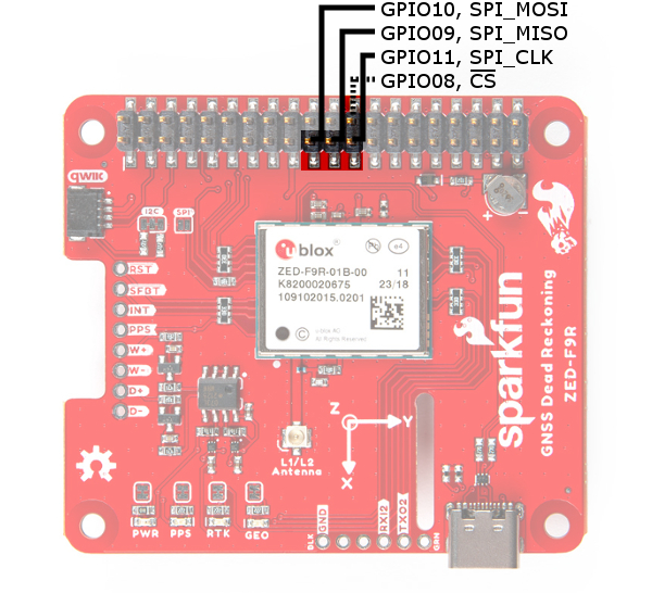
SPI
The pins for SPI (GPIO08, GPIO09, GPIO10, and GPIO11) are connected to the Pi if you decide to use this protocol. As mentioned in the jumpers section, you'll need to close the SPI jumper on the top to enable SPI.
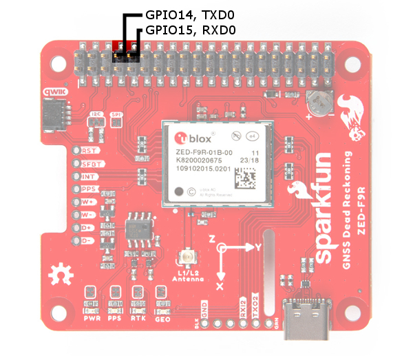
UART
The ZED-F9R's UART1 is connected to the Pi's UART0 port (GPIO14, GPIO15). Keep in mind that the pins are tied to the MISO and MOSI pins. By default, we will be using the UART to read data from the u-blox module.
There is a row of through holes next to the USB Type-C connector labeled for their UART functionality. This is primarily used for RTCM3 correction data. By default, this port will automatically receive and parse incoming RTCM3 strings enabling RTK mode on the board like the other RTK breakout boards for the NEO-M8P-2 and ZED-F9P. The RTCM Correction port pins are arranged to match the industry standard serial connection (aka the 'FTDI' pinout). This pinout is compatible with our Bluetooth Mate and Serial Basic so you can send RTCM correction data from a cell phone or another computer. Note that RTCM3 data can also be sent over I2C, UART1, SPI, or USB if desired.
USB
To connect the ZED-F9R to u-center software, you can attach a USB Type-C cable to the connector. Keep in mind that the power pin is not connected to the USB-C connector. You will need to draw power from the qwiic conenctor or the Pi's 2x20 header pins.
Wheel Tick and Direction Pins
For advanced users that are interested in taking advantage of your vehicle's sensor readings, you can connect the following pins. Caution is advised however as this requires you to open up up the hood of your car and hack into the its system.
- D-: The reference GND pin (
D-) when connecting the direction pin. - D+: The direction pin is labeled as (
D+) tells the ZED-F9R what direction the vehicle is moving (forward/reverse). - W-: The reference GND pin (
W-) when connecting the wheel tick pin. - W+: The wheel tick pin (
W+) tells the ZED-F9R the distance a vehicle's wheel has traveled. Depending on the odometer type that you connect to, the ZED-F9R can also receive speed data from the vehicle.
Broken Out Pins
There are four other pins broken out:
- RESET: The reset pin (
RESET) resets the chip. - SAFEBOOT: The safeboot pin (
SAFEBOOT) is used to start up the IC in safe boot mode, this could be useful if you somehow manage to corrupt the module's Flash memory. - INT: The interrupt pin (
INT) can be used to wake the chip from power save mode. - PPS: The pulse per second pin (
PPS) outputs pulse trains synchronized with the GPS or UTC time grid. The signal defaults to once per second but is configurable over a wide range. Read the u-blox Receiver Protocol Specification in the Resources and Going Further tab for more information.
3D IMU Orientation and Reference
For easy reference, we've documented the IMU's vectors with 3D Cartesian coordinate axes on the top and bottom side of the board. Make sure to orient and mount the board correctly so that the ZED-F9R can accurately calculate navigation information. Remember, it's all relative.
|
|
| Top View with the Axis for Reference | Bottom View with the Axis for Reference |
GPS Capabilities
The ZED-F9R is able to connect to up to four different GNSS constellations simultaneously with the 3D gyro and 3D accelerometer making it very accurate for its size. Below are the listed capabilities of the GPS unit.
| Parameter | Specification | |
|---|---|---|
| Max navigation update rate (RTK) | Priority navigation mode | 30 Hz |
| Non-Priority navigation mode | 2 Hz | |
| Velocity Accuracy | 0.05m/s | |
| Dynamic Attitude Accuracy | Heading | 0.2 degrees |
| Pitch | 0.3 degrees | |
| Roll | 0.5 degrees | |
| Navigation Latency | Priority Navigation Mode | 15ms |
| Max Sensor Output Rate | 100Hz | |
| GNSS | GPS+GLO+GAL +BDS | GPS+GLO+GAL | GPS+GAL | GPS+GLO | BDS+GLO | |
|---|---|---|---|---|---|---|
| Time-To-First-Fix | Cold Start | 26s | 25s | 30s | 25s | 28s |
| Hot Start | 2s | 2s | 2s | 2s | 2s | |
| Aided Start | 3s | 3s | 3s | 3s | 3s | |
| Re-convergence time | RTK | ≤ 10s | ≤ 10s | ≤ 10s | ≤ 10s | ≤ 30s |
| Sensitivity | Tracking and Navigation | -160dBm | -160dBm | -160dBm | -160dBm | -160dBm |
| Reacquisition | -157dBm | -157dBm | -157dBm | -157dBm | -157dBm | |
| Cold Start | -147dBm | -147dBm | -147dBm | -147dBm | -145dBm | |
| Hot Start | -158dBm | -158dBm | -158dBm | -158dBm | -158dBm |
| Horizontal Position Accuracy | PVT | 1.5m CEP | 1.5m CEP | 1.5m CEP | 1.5m CEP | 1.5m CEP |
| SBAS | 1.0m CEP | 1.0m CEP | 1.0m CEP | 1.0m CEP | 1.0m CEP | |
| RTK | 0.01m + 1ppm CEP | 0.01m + 1ppm CEP | 0.01m + 1ppm CEP | 0.01m + 1ppm CEP | 0.01m + 1ppm CEP |
|
| Vertical Position Accuracy | RTK | 0.01m +1ppm R50 | 0.01m +1ppm R50 | 0.01m +1ppm R50 | 0.01m +1ppm R50 | 0.01m +1ppm R50 |
Board Dimensions
The board is slightly bigger than the breakout version. Overall, it is is 65.00mmx56.50mm (2.56"x2.22"). There are 4x mounting holes by each corner of the board.
Hardware Assembly (pHAT)
To get started with your ZED-F9R pHAT, simply plug it into the headers on the Raspberry Pi as shown below. Then connect the necessary peripherals, u.FL connnector to SMA cable, and GPS/GNSS patch antenna. If you need tips on plugging in the U.FL connector, then check out our U.FL tutorial. For secure connections, you may want to add tape or some hot glue for the u.FL cable to provide some strain relief to prevent the cable from disconnecting.
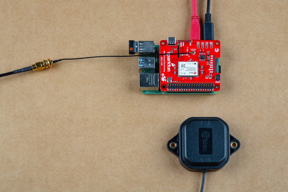
Make sure to secure the board above a vehicle's dashboard using some tape or sticky tack when prototyping and testing. For best signal reception, it is suggested to guide the antenna from the inside of the car and through a window before attaching the GPS on top of a car.
Adding a RTCM Correction Source
As explained earlier for the breakout board, there are a few methods of adding a RTCM correction source. If you have been following along with our GPS-RTK and GPS-RTK2, you can pipe correction data from a wireless network, LoRa, or cellular network. The following example uses the Bluetooth Mate to connect to an Android phone's app. Depending on your personal preference, you can choose a female header or a male header for the Bluetooth Mate. We opted for the female header.
For a low profile, we decided to use 1x6 right angle, male headers. Depending on your application, you can use straight, male headers. As a result, the design of the breakout requires the top of the Bluetooth Mate to face the ZED-F9P. When ready, solder the male headers to the breakout board. In this case, the headers were inserted from the top and soldered on the bottom.
Make sure to connect GND to GND, Rx to Tx, and Rx to Tx by following the silkscreen. Below is an example of what to expect before the pins are soldered. When you are finished soldering the board and cleaning the joints, make sure to stack the board back on the Raspberry Pi.
Configure Your Pi
The Serial peripheral is not turned on by default. There are a few methods to adjust the settings. To enable it, you will need to do the following.
Raspberry Pi Configuration via Desktop GUI
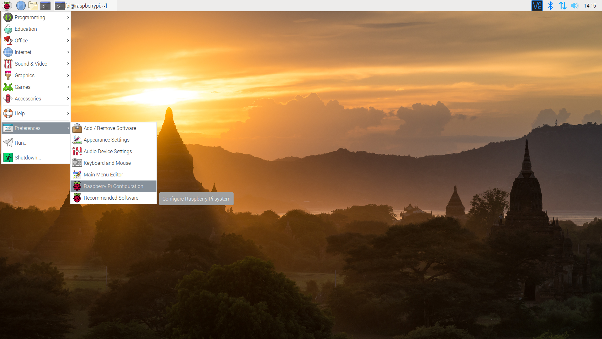
Before we download the Python package, you will need to enable your serial UART port. There are a few methods of enabling the port but we recommend using the GUI: Raspberry Pi Start Menu > Interfaces > Raspberry Pi Configuration.
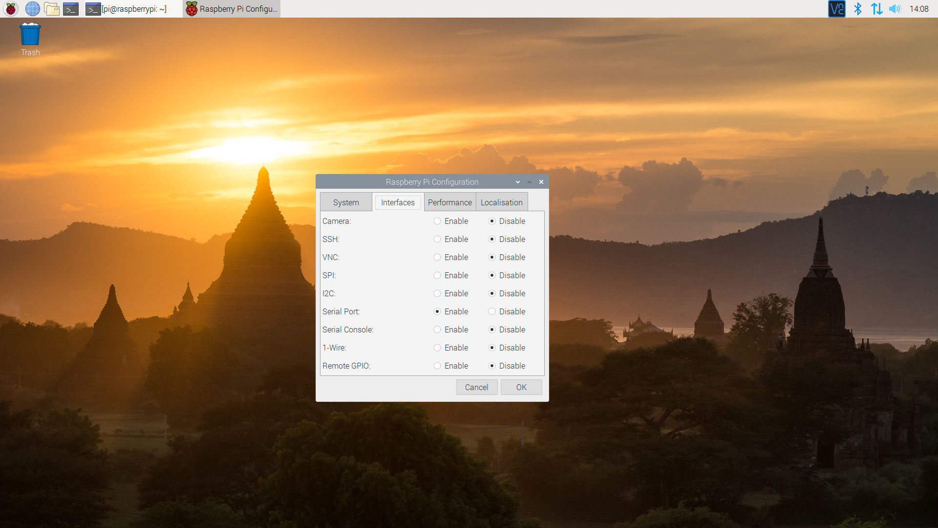
A window will pop up with different tabs to adjust settings. What we are interested is the Interfaces tab. Click on the tab and select Enable for Serial. If you would like to control the Raspberry Pi through the serial port terminal, you can select Enable for Serial Console. Since we are using the serial port to control another serial device, we will be selecting Disable At this point, you can enable additional interfaces depending on your project needs. Click on the OK button to save.
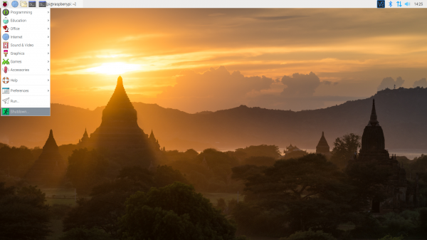
We recommend restarting your Pi to ensure that the changes to take effect. Click on the Pi Start Menu > Preferences > Shutdown. Since we just need to restart, click on the Restart button.
 |
 |
| Shutdown | Turn Off, Restart, Log Off |
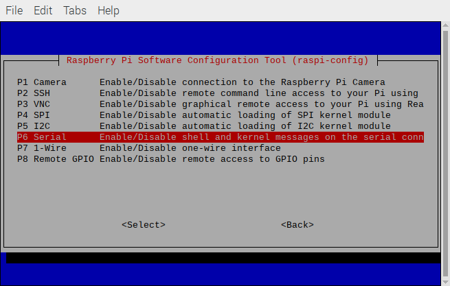
raspi-config Tool via Terminal
If you prefer the old school method using a terminal, we can use raspi-config to enable it.
- Run
sudo raspi-config. - Use the down arrow to select
5 Interfacing Options - Arrow down to
P6 Serial. - Select
noif it asks about using the login shell to be accessible over serial. - Select
yeswhen it asks you to enable hardware serial. - Select
Okto confirm. - Use the right arrow to select the
<Finish>button. - Select
yeswhen it asks to reboot.
The system will reboot. When it comes back up, log in and enter the following command
language:bash
ls /dev/ttyS0
or
language:bash
ls /dev/serial0
The Pi should respond with the port that was entered.
language:bash
/dev/ttyS0
or
language:bash
/dev/serial0
sudo apt-get install minicom/dev/ttyS0 serial port.
sudo minicom -D /dev/ttyS0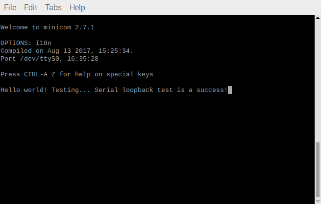
When finished, type CTRL+A followed by X to exit minicom.
U-Blox Python Package
Python Versions and Installing PIP
There are also 2 commonly used Python versions. Even after Python 3 came out many people continued to use 2.7 for many years. Part of the reason is that Python 3 improved on some things and in the process made it not backwards compatible. We recommend using Python 3 since Python 2 has reached its end of life. To see what version of Python your Pi is using, open a command line and type each of the following commands individually to check.
language:bash
python --version
pip --version
If you are not using Python 3, then we'll need to open the *.bashrc file and add an alias.
First, you will need to update the python installation package by running the following command to install pip for Python 3. Execute the following commands.
language:bash
sudo apt-get install python3-pip
Type the following command to open the file.
language:bash
nano ~/.bashrc
Then add the following lines at the end. That should tell the computer whenever you want to run python to look for the file located at /usr/bin/python3.
language:bash
alias python='/usr/bin/python3'
alias pip=pip3
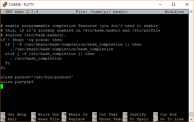
To exit nano type CTRL + X and then hit Y when it asks you if you want to save and then ENTER. You can now either reboot or type the following to force the Pi to run the *.bashrc file again.
language:bash
source ~/.bashrc
Once adjusted, type the following command to ensure that pip is up to date.
language:bash
python -m pip install --upgrade pip
Qwiic Python Package
We will also need to install the Qwiic Python libraries. This will automatically download a folder containing all the Qwiic_Py files and dependencies to your Raspberry Pi. Run the following command to automatically install the modules for SparkFun devices. Note that while the u-Blox Python package is included in the Qwiic_Py, the pHAT uses the hardware UART instead of I2C bus. To ensure that you are installing to the correct path for Python 3, make sure that you use pip3.
language:bash
sudo pip3 install sparkfun-qwiic
uninstall with the command: sudo pip3 uninstall sparkfun-qwiicPython Example Code
We will be using the example in the uBlox GPS Py GitHub repo. This should automatically install the package if you installed Qwiic_Py. Feel free to check out the associated ReadtheDocs as well!
Connecting the GPS-RTK to a Correction Source
What is GPS RTK?
GPS-RTK Hookup Guide
GPS-RTK2 Hookup Guide
Resources and Going Further
Now that you've successfully got your GPS receiver up and running, it's time to incorporate it into your own project! For more information, check out the resources below:
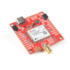
- SparkFun u-Blox ZED-F9R Breakout
- u.FL Version, v1.2
- SMA Version, v1.1
- GitHub
- SparkFun u-Blox ZED-F9R pHAT
- u-blox Module Documentation
- SFE Product Showcase
Are you looking for a GPS receivers? Check out the following GPS boards from the SparkFun catalog!
SparkFun RTK Express Plus Kit
GPS-18589
Need some inspiration for your next project? Check out some of these related tutorials:
GPS Shield Hookup Guide
Qwiic GPS Clock
Artemis Global Tracker Hookup Guide
MicroMod GNSS Function Board - ZED-F9P Hookup Guide
Or check out this blog post for ideas.