GPS Basics
The Basics of GPS
You have probably used or benefitted from a GPS receiver. They are found in most smartphones, many new automobiles, and they are used to track commerce all over the globe. These tiny devices can instantaneously give your exact position and time, almost anywhere on the planet, for free! All you need is a GPS receiver, and receivers are getting less expensive and smaller every day.
Don't take these tiny, inexpensive modules for granted. There are decades of engineering that went in to giving you accurate position anytime, anywhere. Dozens of GPS satellites, all containing extremely accurate atomic clocks, have been launched since the late 70's, and launches continue to this day. The satellites continuously send data down to earth over dedicated RF frequencies. Our pocket-sized GPS receivers have tiny processors and antennas that directly receive the data sent by the satellites and compute your position and time on the fly. Simply amazing.
Suggested Reading
There are some concepts that this tutorial builds upon and that you may need to know or prepare before starting:
Serial Communication
Connector Basics
Binary
Logic Levels
Serial Terminal Basics
Suggesting Viewing
How Does GPS Work?
GPS receivers use a constellation of satellites and ground stations to compute position and time almost anywhere on earth.
At any given time, there are at least 24 active satellites orbiting over 12,000 miles above earth. The positions of the satellites are constructed in a way that the sky above your location will always contain at most 12 satellites. The primary purpose of the 12 visible satellites is to transmit information back to earth over radio frequency (ranging from 1.1 to 1.5 GHz). With this information and some math, a ground based receiver or GPS module can calculate its position and time.
How Does a GPS Receiver Calculate Its Position and Time?
The data sent down to earth from each satellite contains a few different pieces of information that allows your GPS receiver to accurately calculate its position and time. An important piece of equipment on each GPS satellite is an extremely accurate atomic clock. The time on the atomic clock is sent down to earth along with the satellite’s orbital position and arrival times at different points in the sky. In other words, the GPS module receives a timestamp from each of the visible satellites, along with data on where in the sky each one is located (among other pieces of data). From this information, the GPS receiver now knows the distance to each satellite in view. If the GPS receiver’s antenna can see at least 4 satellites, it can accurately calculate its position and time. This is also called a lock or a fix.
Did you catch all of that? If not or if you want more, check out a much more detailed explanation, in volume 1 of GPS Fundamentals by Dan Doberstein. Volume 1 has been released for free, but you must support the author to read volume 2.
There is another piece of the global positioning system we haven’t talked about. Along with satellites and GPS receivers, there are ground based stations that can communicate with the satellite network and some GPS receivers. This system is formally called the control segment and increases the accuracy of your GPS receiver. Common systems that use the control segment to improve accuracy are WAAS and DGPS. WAAS is common on most GPS receivers and improves accuracy to about 5 meters. DGPS requires a specific type of GPS receiver and gets centimeter accuracy. DGPS units are also expensive and tend to be larger because they require an additional antenna.
GPS Accuracy
GPS Accuracy depends on a number of variables, most notably signal to noise ratio (noisy reception), satellite position, weather and obstructions such as buildings and mountains. These factors can create errors in your perceived location. Signal noise usually creates an error from around one to ten meters. Mountains, buildings and other things that might obstruct the path between the receiver and the satellite can cause three times as much error as signal noise. A GPS receiver must be able to get a lock on 4 satellites to be able to solve for a position. The first lock it gets allows the receiver to obtain the almanac information and thus what other satellites it should listen for. Although it is possible to get a position from less than 4 satellites, the margin of error of this position can be rather large. Your most accurate read of your location comes when you have a clear view of a clear sky away from any obstructions and under more than four satellites. To combat these errors, a couple of different assistants have been created.
Assisted GPS
One of these ancillaries is Assisted GPS or AGPS. This method uses wireless (ground-based) networks to help relay between the satellite and the receiver when the GPS signal is weak or not able to be picked up. There are two ways AGPS can help out. The first is to provide the receiver with the proper almanac data and the precise time. The second utilizes the higher computing power and good satellite signal of the ground base to interpret the broken or fragmented information the receiver is receiving to provide a more accurate position reading to the receiver. AGPS is mostly accomplished by GPS receivers mounted on cellular towers. When communicating with these receivers, the GPS can acquire a lock on the satellite more quickly as well as receive more accurate information. This method is what is used for GPS in mobile phones and why they’re sometimes more accurate than the GPS receivers on their own. But AGPS is present in more devices than just cellphones; it's even available in cameras and some vehicles. It’s most beneficial in cities where the GPS signal may have a difficult time making it through the dense maze of the buildings.
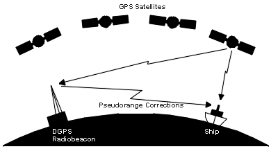
Differential GPS
Another method is Differential GPS or DGPS. DGPS also uses ground or fixed GPS stations to determine the location, but differs in that it finds the difference between both the satellite and the ground location reading. These ground stations may be up to 200 nautical miles from the receiver, and it is important to note that accuracy deteriorates the further you are from the ground station. DGPS is accomplished by a ground station broadcasting a signal which dictates the error between the actual pseudorange and the measured pseudorange. This value is calculated by multiplying the speed of light by the time it takes the signal to travel from the satellite to the receiver. As an example, one form of DGPS is Wide Area Augmentation System or WAAS.
Originally developed by the FAA to assist aircraft GPS, WAAS uses a system of specifically built ground stations. WAAS holds a specific set of accuracy standards that ground station measurements must meet. Laterally and vertically, WAAS must be accurate to within 7.6 meters 95% of the time. These ground stations send their measurements to master stations which send the corrections to WAAS satellites every 5 seconds or quicker. From the Satellite, a signal is broadcast back to the receivers on earth where the corrections are used to improve the GPS accuracy. In some locations, WAAS is able to provide an accuracy of 1 meter lateral and 1.5 meters vertically. While WAAS is only present in North America, similar systems are in place in many other parts of the world.
What is GPS RTK?
Message Formats
GPS data is displayed in different message formats over a serial interface. There are standard and non-standard (proprietary) message formats. Nearly all GPS receivers output NMEA data. The NMEA standard is formatted in lines of data called sentences. Each sentence contains various bits of data organized in comma delimited format (i.e. data separated by commas). Here’s example NMEA sentences from a GPS receiver with satellite lock (4+ satellites, accurate position):
language:bash
$GPRMC,235316.000,A,4003.9040,N,10512.5792,W,0.09,144.75,141112,,*19
$GPGGA,235317.000,4003.9039,N,10512.5793,W,1,08,1.6,1577.9,M,-20.7,M,,0000*5F
$GPGSA,A,3,22,18,21,06,03,09,24,15,,,,,2.5,1.6,1.9*3E
For example, the GPGGA sentence contains the follow:
- Time: 235317.000 is 23:53 and 17.000 seconds in Greenwich mean time
- Longitude: 4003.9040,N is latitude in degrees.decimal minutes, north
- Latitude: 10512.5792,W is longitude in degrees.decimal minutes, west
- Number of satellites seen: 08
- Altitude: 1577 meters
The data is separated by commas to make it easier to read and parse by computers and microcontrollers. This data is sent out on the serial port at an interval called the update rate. Most receivers update this information once per second (1Hz), but more advanced receivers are capable multiple updates per second. 5 to 20Hz is possible with modern receivers.
Reading GPS Data
Most GPS modules have a serial port, which makes them perfect to connect to a microcontroller or computer.
Connecting to a Microcontroller
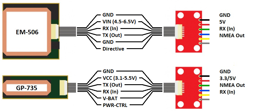
Once a GPS module is powered, NMEA data (or another message format) is sent out of a serial transmit pin (TX) at a specific baud rate and update rate, even if there is no lock. To have your microcontroller read the NMEA data, all that is needed is to connect the TX pin of the GPS to the RX (receive) pin on the microcontroller. To configure the GPS module, you will need to also connect the RX pin of the GPS to the TX pin of the microcontroller.
It is common for the microcontroller to parse the NMEA data. Parsing is simply removing the chunks of data from the NMEA sentence so the microcontroller can do something useful with the data.
For example, the microcontroller might need to read only the altitude of your GPS.
language:bash
$GPGGA,235317.000,4003.9039,N,10512.5793,W,1,08,1.6,1577.9,M,-20.7,M,,0000*5F
Instead of dealing with all of this text, the microcontroller can parse the GPGGA sentence and end up with only the altitude (in meters).
language:bash
1577
Once the microcontroller can grab the data needed, the information can be manipulated to create other interactions on the microcontroller.
The Arduino platform can parse NMEA data easily with the help of the Tiny GPS library. Check out the GPS Shield Getting Started Guide for a walk-through example on how to connect an Arduino to a GPS module and parse NMEA sentences.
Connecting to a Computer
A simple way to see the NMEA data directly is to connect the GPS module to a computer. For the connections, all that is needed is to power the GPS with the FTDI basic (in this case 5V and GND), then connect the TX pin of the GPS to the RX pin on the FTDI Basic.

Next, open a serial terminal program at the same baud rate of your GPS module. Even if the GPS does not have a lock, you should see NMEA sentences steaming by.
language:bash
$GPRMC,235316.000,A,4003.9040,N,10512.5792,W,0.09,144.75,141112,,*19
$GPGGA,235317.000,4003.9039,N,10512.5793,W,1,08,1.6,1577.9,M,-20.7,M,,0000*5F
$GPGSA,A,3,22,18,21,06,03,09,24,15,,,,,2.5,1.6,1.9*3E
Configuring a GPS Receiver
To configure a GPS receiver, knowing the type of chipset your GPS is using is very important. The GPS chipset contains a powerful processor that is responsible for the user interface, all of the calculations, as well as analog circuitry for the antenna. The chipset also allows for data to be sent to the GPS receiver to configure parameters like, update rate, baud rate, sentence selection, etc.
In order to send commands over a serial interface to a GPS receiver, you will need a command set or reference manual. Before diving too far into the command set for a given module, be sure to check with the vendor. Many chipset vendors provide software that allows you to easily communicate and configure the GPS module over a serial port.
The following are datasheets and command sets for some of the more common chipsets.
- SiRF chipsets
- U-Blox chipsets
- SkyTraq chipsets
Some chipsets allow for alternate protocols such as SiRF binary (SiRF chipset), UBX (ublox chipset), or a proprietary messages. These protocols contain the same information, but communicate using binary (instead of ASCII) for faster communication.
When communicating with a GPS receiver, most commands need to be terminated by a checksum. In most cases, you need to XOR each of your sentences. Here is a simple XOR online calculator.
Ready to get hands-on with GPS?
We've got a page just for you! We'll walk you through the basics of how GPS works, the hardware needed, and project tutorials to get you started.
GPS Glossary
Accuracy - How accurate is GPS? Well, it varies a bit, but you can usually find out where you are, anywhere in the world, within 30 seconds, down to +/– 5 meters. Amazing! The +/– is there because accuracy can vary between modules, time of day, clarity of reception, etc. Most modules can get down to +/-3m with WAAS enabled, but if you need sub-meter or centimeter accuracy, it gets really expensive and requires something called DGPS.
Overall, to get the best accuracy from your GPS, you must be in clear view of the sky and moving.
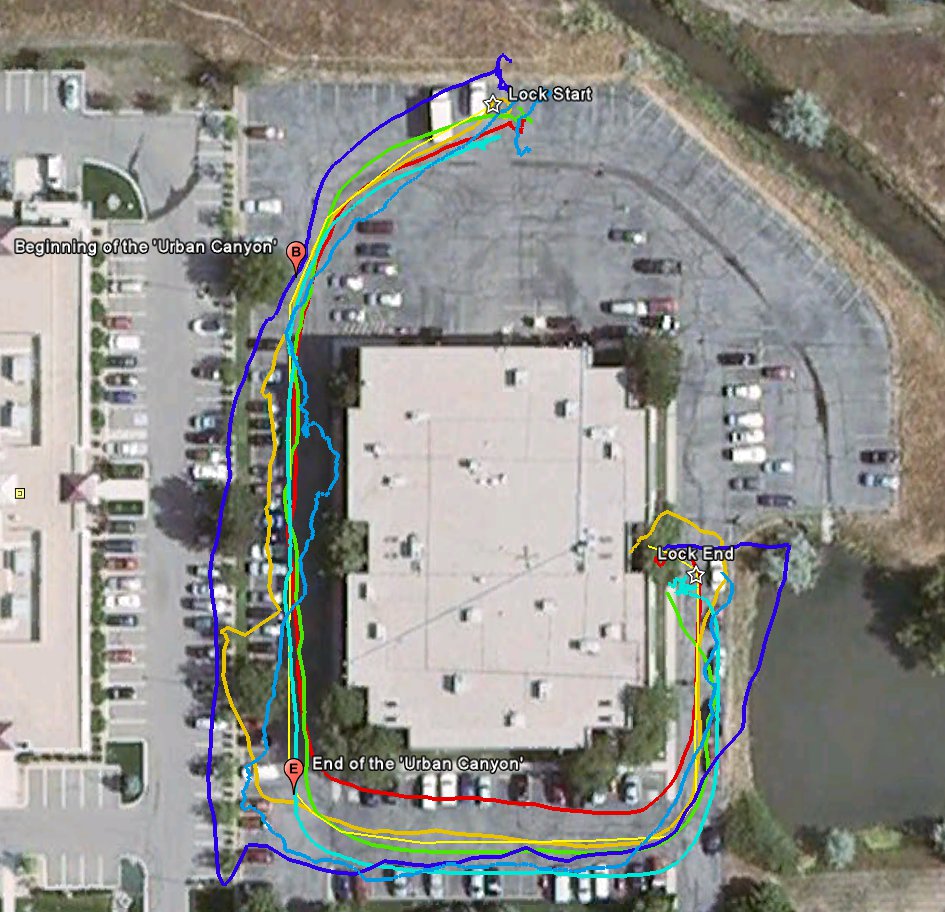
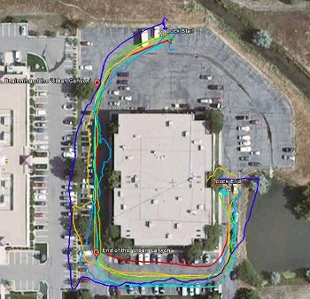 Logged and plotted GPS waypoints around the old SparkFun headquarters. Each track represents a different type of GPS module.
If you notice in the example tracks around the SparkFun building, the GPS positions bounce around at 'Lock Start' and 'Lock End'. This is when the GPS module isn't moving. The GPS has some amount of error (~5 meters), and you can see it when not moving. Once the module starts moving, the track is relatively accurate, and the GPS can 'guess' your track. However, notice on the approach to the Urban Canyon, which is in between two tall buildings, the accuracy can suffer. Remember, the GPS signals are being transmitted from satellites that are not necessarily over you head; some can be close to the horizon. Also, the RF signals can reflect off of buildings/objects and create something called multi-path interference. Always keep in mind, GPS works best with a full view of the sky.
Antenna - Remember, that little GPS module is receiving signals from satellites about 12,000 miles away, not only above your head, but anywhere in the sky. For the best performance, you want a clear path between the antenna and most of the sky. Weather, clouds, snow storms, shouldn't affect the signal, but things like trees, buildings, mountains, the roof over your head, will all create unwanted interference and your GPS accuracy will suffer.
There are many antenna choices, but these are some of the most common.
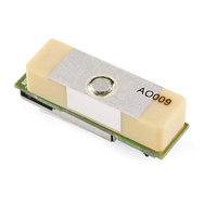 The smallest and most common form of antenna is the ceramic patch antenna.
This antenna is low profile, inexpensive, and compact, but it has lower reception compared to other types of antennas. This antenna needs to face upwards with a clear view of the sky to get good a good signal, i.e. the gain of the antenna is greatest when facing up.
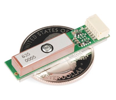
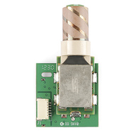 Some GPS modules use helical antennas.
This antenna can take up more room than the ceramic patch, but the shape of the antenna allows for a better signal in any orientation, at the expense of slightly lower gain in any one specific orientation.
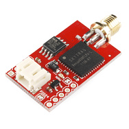
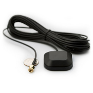 Some modules can be used with a SMA antenna attachment.
The SMA attachment gives you the ability to mount your antenna in a different location than your main circuit. This can be beneficial if your main system is not in good view of the sky. For example, inside of a building or in a car.
Baud Rate - GPS receivers send serial data out of a transmit pin (TX) at a specific bit rate. The most common is 9600bps for 1Hz receivers but 57600bps is becoming more common. Check the datasheet of the receiver for more information.
Channels - The number of channels that the GPS module runs will affect your time to first fix (TTFF). Since the module doesn’t know which satellites are in view, the more frequencies/channels it can check at once, the faster a fix will be found. After the module gets a lock or fix, some modules will shut down the extra blocks of channels to save power. If you don’t mind waiting a little longer for a lock, 12 or 14 channels will work just fine for tracking.
Chipset - The GPS chipset is responsible for doing everything from performing calculations, to providing the analog circuitry for the antenna, to power control, to the user interface. It’s a lot of work, and yet that’s exactly what these tiny GPS units are doing. The chipset is independent of the antenna type, therefore you can have a range of different antennas for GPS modules with specific chipsets. Common chipsets are ublox, SiRF, and SkyTraq and all contain very powerful processors that allow for fast acquisitions times and high reliability. The differences between chipsets usually falls on a balance between power consumption, acquisition times, and accessibility of hardware.
DGPS - Differential GPS or DGPS is a specific type of GPS receiver. DGPS receivers have additional antenna that receive signals not only from satellites but directly from ground stations. DGPS devices usually require two antennas. These are much larger and more expensive than your standard GPS device but can provide centimeter accuracy in position.
Gain - The gain is the efficiency of the antenna in any given orientation. This applies to both transmitting antennas and receiving antennas.
Lock or Fix - When a GPS receiver has a lock or fix, there are at least 4 satellites in good view and you can get accurate position and time.
NMEA - This is a common data format that most GPS modules use. NMEA data is displayed in sentences and sent out of the GPS modules serial transmit (TX) pin. The NMEA sentences contain all of the useful data, (position, time, etc.).
Power - GPS modules are not power hogs, but they do need some juice to number crunch the data from the satellites and to obtain a lock. On average, a common GPS module, with a lock, draws around 30mA at 3.3V. Also, keeping the start-up time low, saves power.
PPS - Pulse per second. This is an output pin on some GPS modules. Generally, when this pin toggles, once a second, you can synchronize your system clock to the GPS clock.
Start-up Times (Hot, Warm, and Cold) - Some GPS modules have a super-capacitor or battery backup to save previous satellite data in volatile memory after a power down. This helps decrease the TTFF on subsequent power-ups. Also, a faster start time translates into less overall power draw.
Cold Start - If you power down the module for a long period of time and the backup cap dissipates, the data is lost. On the next power up, the GPS will need to download new almanac and ephemeris data.
Warm Start - Depending on how long your backup power lasts, you can have a warm start, which means some of the almanac and ephemeris data is preserved, but it might take a bit extra time to acquire a lock.
Hot Start: A hot start means all of the satellites are up to date and are close to the same positions as they were in the previous power on state. With a hot start the GPS can immediately lock.
Trilateration - The mathematical method used to calculate position using multiple reference points. In order for a GPS receiver to compute accurate position and time, it needs to be in good view of at least 4 satellites in the sky. This is called a GPS lock or fix. We all know how to use triangulation to calculate the distance to an object using two reference points (x, y). However, with GPS, we need to determine 4 values, i.e. latitude, longitude, elevation, and time.
TTFF - Time to first fix. The time it takes, after power-on, to accurately compute your position and time using at least 4 satellites. If you are in a location with a bad view of the sky, the TTFF can be very long.
Update Rate - The update rate of a GPS module is how often it calculates and reports its position. The standard for most devices is 1Hz (once per second). UAVs and other fast vehicles may require increased update rates. 5 and even 10Hz update rates are becoming available in low cost modules. Keep in mind, that higher update rates mean there’s more NMEA sentences flying out of the module.
WAAS - The WAAS, or wide area augmentation system, is a network of ground based stations (in North America) that transmit correction data back to the satellites. The WAAS gives close to 5 meter accuracy on position. Other countries have similar systems, for example the European system is called EGNOS, the Japenese system is MSAS, and India has GAGAN. Most GPS receivers have WAAS enabled by default and support EGNOS, MSAS, and GAGAN.


Troubleshooting
Lock Problems
Mikal Hart's TinyGPS++ library is excellent to get you up and running quickly with GPS. However, that might not be the case if you are between urban canyons, inside a concrete building, or a black pit of doom for all wireless signals to/from the outside world. The problem that we found is when GPS is used indoors, and, in the case of the SparkFun building, it makes seriously difficult to get a GPS lock. We have lots of concrete, metal girders, and a large solar array that wreaks havoc with GPS signals (and pretty much all cellular carriers for that matter).
If you ever have issues seeing the GPS data when using a library or the output is incomplete, you may need to move to a different location to view more satellites. Sometimes moving the GPS module a few steps to a different spot or to the perimeter of a building can help. To check the amount of satellites in view, you can observe 6th and 7th field of the GPGAA sentence to see if you are having any lock problems. Below is an example GPGGA sentence when a GPS module does not have a satellite lock. As you can see, the output indicates that the data is invalid since there is no GPS fix and there are no satellites in view.
language:bash
$GPGGA,105317.709,8960.0000,N,00000.0000,E,0,0,,137.0,M,13.0,M,,*4C
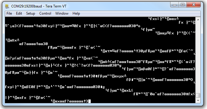
Baud Rate Mismatch
If you are passing data from the GPS module's serial UART to your serial monitor and all you see is "garbage" like the image below, check to make sure the baud rate set is correctly. Depending on the GPS module, the baud rate can be vary. Make sure to check the datasheet for your GPS module to ensure that the baud rate is the same.
Resources and Going Further
You should now have a clear understanding of how GPS units work and how to implement them into your next project. For more great project ideas check out these other SparkFun tutorials.
Gyroscope
How to Power a Project
How to Use a Breadboard
Accelerometer Basics
Electric Power
Need some inspiration for your next project? Check out some of these related tutorials:
Qwiic GPS Clock
SparkFun GPS-RTK Dead Reckoning ZED-F9K Hookup Guide
SparkFun RTK Facet Hookup Guide
SparkFun RTK Facet L-Band Hookup Guide
Or check out these blog posts.