SparkFun GPS-RTK Dead Reckoning ZED-F9R Hookup Guide
 bboyho,
  Elias The Sparkiest
Hardware Overview (pHAT)
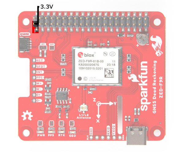
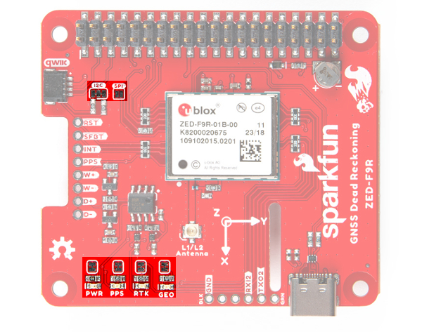
Power
Power for this board is 3.3V. Unlike the breakout board, the pHAT version pulls power from the Raspberry Pi's 3.3V pin on the 2x20 header. The Qwiic Connector's voltage pin is connected to this rail. The 3.3V pin should only be provided a clean 3.3V power signal from the Pi.
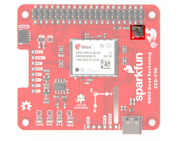
Backup Battery
Just like the breakout board, the small metal disk in the just to the right of the ZED-F9R module is a small lithium battery. This battery does not provide power to the IC like the 3.3V system does, but to relevant systems inside the IC that allow for a quick reconnection to satellites. The time to first fix will about ~26 seconds, but after it has a lock, that battery will allow for a two second time to first fix. This is known as a hot start and lasts for four hours after the board is powered down. The battery provides over a years worth of power to the backup system and charges slowly when the board is powered. To charge it to full, leave your module plugged in for 48 hours.
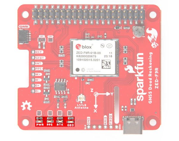
LEDs
Just like the breakout board, there are four LEDs on the bottom left of the board. Starting from the left:
- PWR: The power LED labeled as
PWRwill illuminate when 3.3V is activated. - PPS: The pulse per second LED labelled as
PPSwill illuminate each second once a position lock has been achieved. This generates a pulse that is synchronized with a GPS or UTC time grid. By default, you'll see one pulse a second. - RTK: The
RTKLED will be illuminated constantly upon power up. Once RTCM data has been successfully received it will begin to blink. This is a good way to see if the ZED-F9R is getting RTCM from various sources. Once an RTK fix is obtained, the LED will turn off. - GEO: The
GEOLED can be configured to turn on/off for geofencing applications.
Jumpers
On the top side of the board, you will notice a few jumper pads.
- I2C: This three way jumper labeled
I2Cconnects two pull-up resistors to the I2C data lines. For general use, you can leave this jumper unmodified. If you have many I2C devices (about 7x devices, each with their own pull-up resistors), you will need to cut the jumpers. - SPI: The jumper labeled
SPIis open by default. Closing the jumper with solder enables the SPI data bus thus disabling the UART functions on those lines. This also disables I2C interface. USB will still function. - PWR: Starting from the right side is a jumper labeled
PWR. If you cut this trace, it will disconnect the Power LED. - PPS: On the left of the jumper is the
PPSjumper that when cut disconnects the PPS LED. - GEO: Cutting the
GEOjumper disconnect the LED used to indicate when we reach a certain condition for geofencing applications. - RTK: The
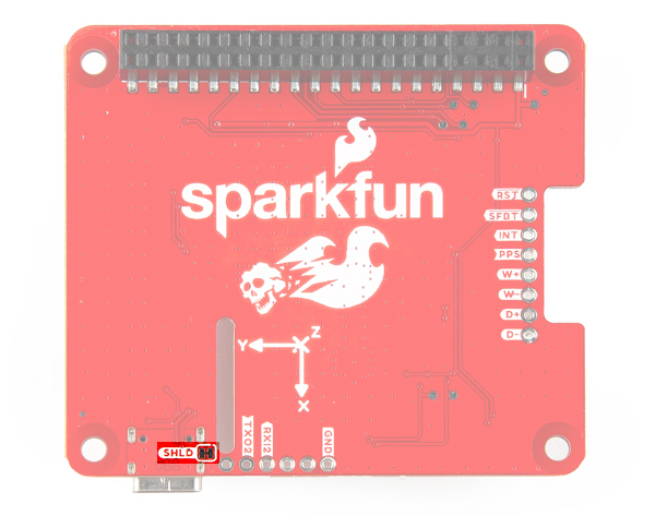
RTKjumper disconnects the LED used for RTK applications. - SHLD: On the back of the board, the
SHLDjumper connects the USB Type C connector's shield pin to GND. Cut this to isolate the USB Type C connector's shield pin. This was added in v1.1.
For more information, check out our tutorial on How to Work with Jumper Pads and PCB Traces .
 |
 |
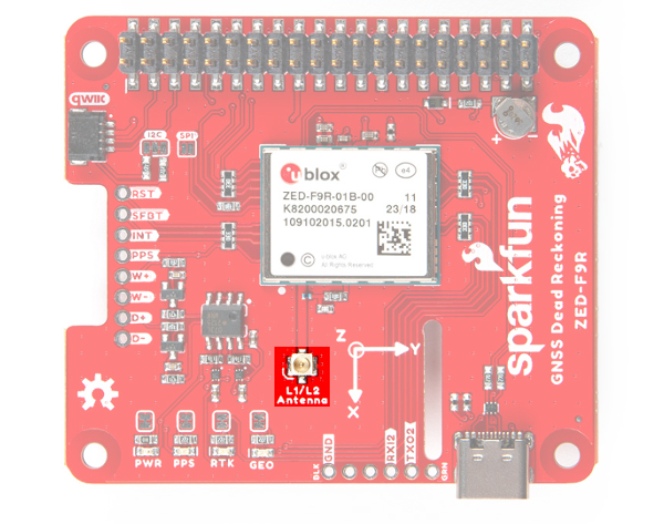
U.FL Connector
The ZED-F9R requires a good quality L1/L2 GPS or GNSS (preferred) antenna. A U.FL connector is provided. Note: U.FL connectors are rated for only a few mating cycles (about 30) so we recommend you set it and forget it. You may need to secure the u.FL to SMA cable depending on your application. For more information on working with u.FL connectors, we recommend checking out our tutorial about using u.FL connectors.
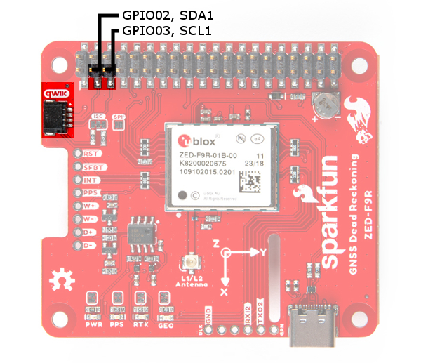
Qwiic and I2C
After stacking the pHAT on a Raspberry Pi, you still have access to the I2C pins (GPIO02 and GPIO03) on the top side. Alternatively, you can use the Qwiic connector to daisy chain additional I2C devices on the bus. The Qwiic ecosystem is made for fast prototyping by removing the need for soldering. All you need to do to connect additional Qwiic devices is plug a Qwiic cable into the Qwiic connector and voila! You can also access those pins from the 2x20 header.
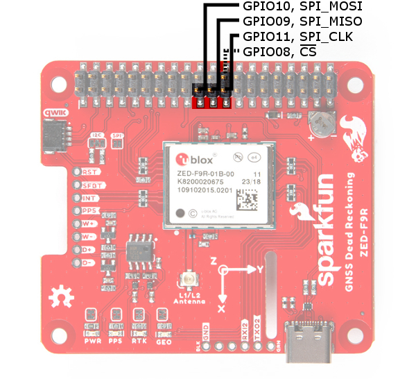
SPI
The pins for SPI (GPIO08, GPIO09, GPIO10, and GPIO11) are connected to the Pi if you decide to use this protocol. As mentioned in the jumpers section, you'll need to close the SPI jumper on the top to enable SPI.
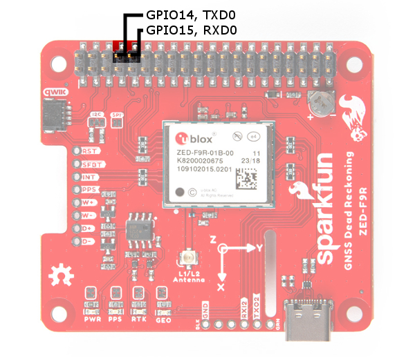
UART
The ZED-F9R's UART1 is connected to the Pi's UART0 port (GPIO14, GPIO15). Keep in mind that the pins are tied to the MISO and MOSI pins. By default, we will be using the UART to read data from the u-blox module.
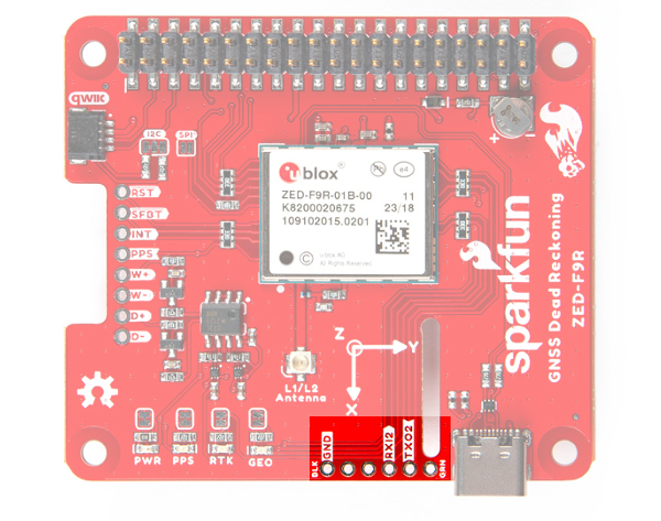
There is a row of through holes next to the USB Type-C connector labeled for their UART functionality. This is primarily used for RTCM3 correction data. By default, this port will automatically receive and parse incoming RTCM3 strings enabling RTK mode on the board like the other RTK breakout boards for the NEO-M8P-2 and ZED-F9P. The RTCM Correction port pins are arranged to match the industry standard serial connection (aka the 'FTDI' pinout). This pinout is compatible with our Bluetooth Mate and Serial Basic so you can send RTCM correction data from a cell phone or another computer. Note that RTCM3 data can also be sent over I2C, UART1, SPI, or USB if desired.
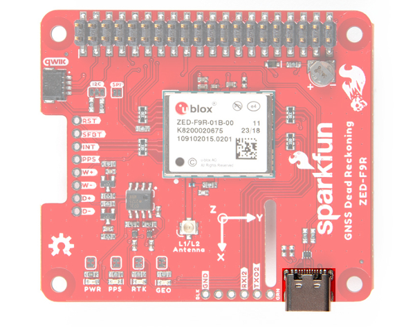
USB
To connect the ZED-F9R to u-center software, you can attach a USB Type-C cable to the connector. Keep in mind that the power pin is not connected to the USB-C connector. You will need to draw power from the qwiic conenctor or the Pi's 2x20 header pins.
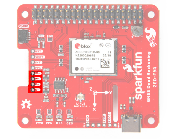
Wheel Tick and Direction Pins
For advanced users that are interested in taking advantage of your vehicle's sensor readings, you can connect the following pins. Caution is advised however as this requires you to open up up the hood of your car and hack into the its system.
- D-: The reference GND pin (
D-) when connecting the direction pin. - D+: The direction pin is labeled as (
D+) tells the ZED-F9R what direction the vehicle is moving (forward/reverse). - W-: The reference GND pin (
W-) when connecting the wheel tick pin. - W+: The wheel tick pin (
W+) tells the ZED-F9R the distance a vehicle's wheel has traveled. Depending on the odometer type that you connect to, the ZED-F9R can also receive speed data from the vehicle.
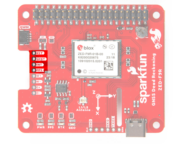
Broken Out Pins
There are four other pins broken out:
- RESET: The reset pin (
RESET) resets the chip. - SAFEBOOT: The safeboot pin (
SAFEBOOT) is used to start up the IC in safe boot mode, this could be useful if you somehow manage to corrupt the module's Flash memory. - INT: The interrupt pin (
INT) can be used to wake the chip from power save mode. - PPS: The pulse per second pin (
PPS) outputs pulse trains synchronized with the GPS or UTC time grid. The signal defaults to once per second but is configurable over a wide range. Read the u-blox Receiver Protocol Specification in the Resources and Going Further tab for more information.
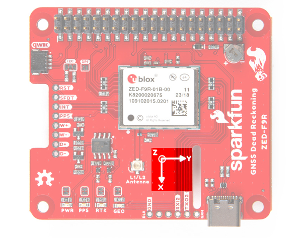
3D IMU Orientation and Reference
For easy reference, we've documented the IMU's vectors with 3D Cartesian coordinate axes on the top and bottom side of the board. Make sure to orient and mount the board correctly so that the ZED-F9R can accurately calculate navigation information. Remember, it's all relative.
 |
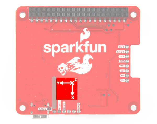 |
| Top View with the Axis for Reference | Bottom View with the Axis for Reference |
GPS Capabilities
The ZED-F9R is able to connect to up to four different GNSS constellations simultaneously with the 3D gyro and 3D accelerometer making it very accurate for its size. Below are the listed capabilities of the GPS unit.
| Parameter | Specification | |
|---|---|---|
| Max navigation update rate (RTK) | Priority navigation mode | 30 Hz |
| Non-Priority navigation mode | 2 Hz | |
| Velocity Accuracy | 0.05m/s | |
| Dynamic Attitude Accuracy | Heading | 0.2 degrees |
| Pitch | 0.3 degrees | |
| Roll | 0.5 degrees | |
| Navigation Latency | Priority Navigation Mode | 15ms |
| Max Sensor Output Rate | 100Hz | |
| GNSS | GPS+GLO+GAL +BDS | GPS+GLO+GAL | GPS+GAL | GPS+GLO | BDS+GLO | |
|---|---|---|---|---|---|---|
| Time-To-First-Fix | Cold Start | 26s | 25s | 30s | 25s | 28s |
| Hot Start | 2s | 2s | 2s | 2s | 2s | |
| Aided Start | 3s | 3s | 3s | 3s | 3s | |
| Re-convergence time | RTK | ≤ 10s | ≤ 10s | ≤ 10s | ≤ 10s | ≤ 30s |
| Sensitivity | Tracking and Navigation | -160dBm | -160dBm | -160dBm | -160dBm | -160dBm |
| Reacquisition | -157dBm | -157dBm | -157dBm | -157dBm | -157dBm | |
| Cold Start | -147dBm | -147dBm | -147dBm | -147dBm | -145dBm | |
| Hot Start | -158dBm | -158dBm | -158dBm | -158dBm | -158dBm |
| Horizontal Position Accuracy | PVT | 1.5m CEP | 1.5m CEP | 1.5m CEP | 1.5m CEP | 1.5m CEP |
| SBAS | 1.0m CEP | 1.0m CEP | 1.0m CEP | 1.0m CEP | 1.0m CEP | |
| RTK | 0.01m + 1ppm CEP | 0.01m + 1ppm CEP | 0.01m + 1ppm CEP | 0.01m + 1ppm CEP | 0.01m + 1ppm CEP |
|
| Vertical Position Accuracy | RTK | 0.01m +1ppm R50 | 0.01m +1ppm R50 | 0.01m +1ppm R50 | 0.01m +1ppm R50 | 0.01m +1ppm R50 |
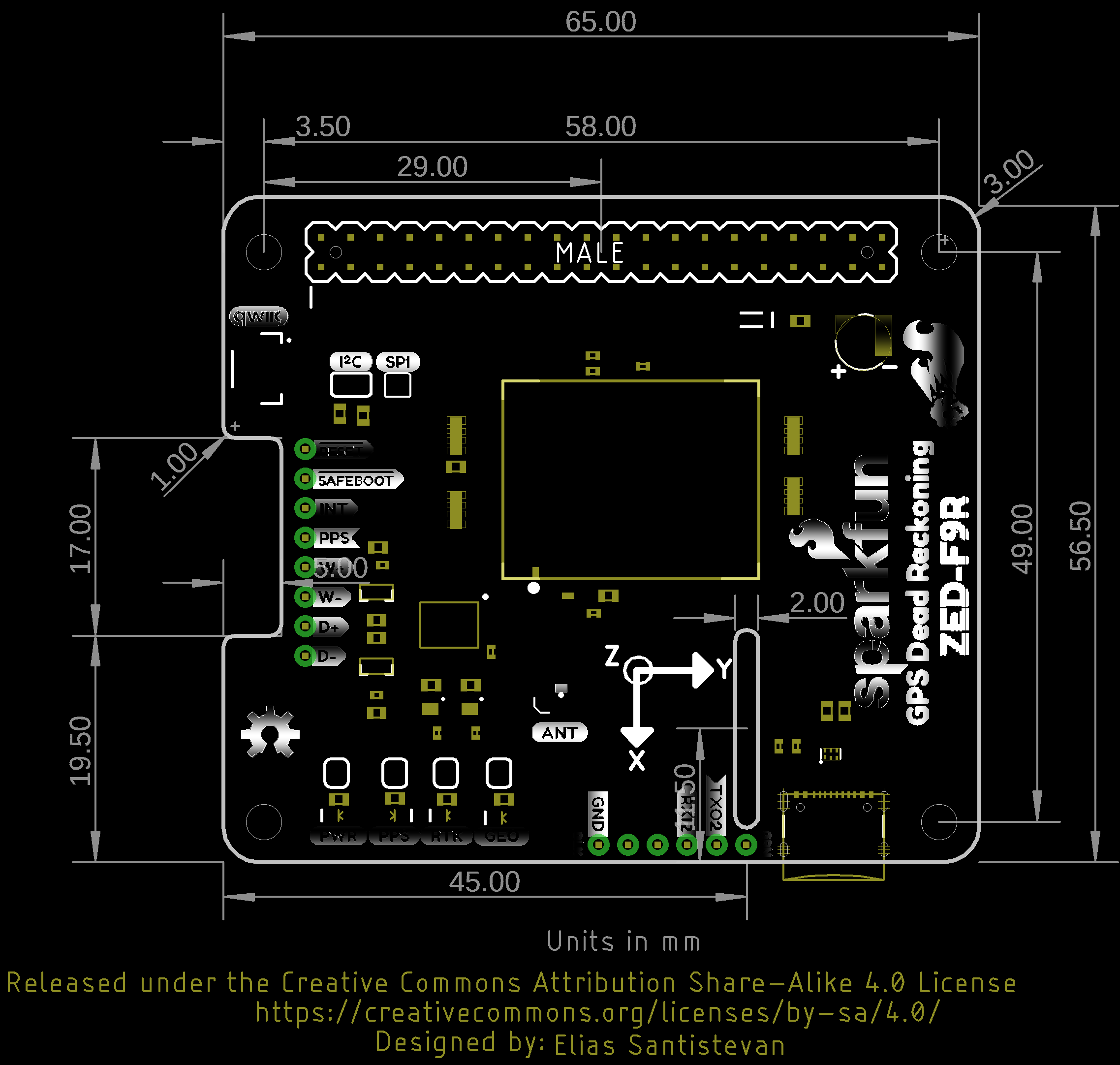
Board Dimensions
The board is slightly bigger than the breakout version. Overall, it is is 65.00mmx56.50mm (2.56"x2.22"). There are 4x mounting holes by each corner of the board.