mbed Starter Kit Experiment Guide
This Tutorial is Retired!
This tutorial covers concepts or technologies that are no longer current. It's still here for you to read and enjoy, but may not be as useful as our newest tutorials.
Experiment 4: Accelerometer
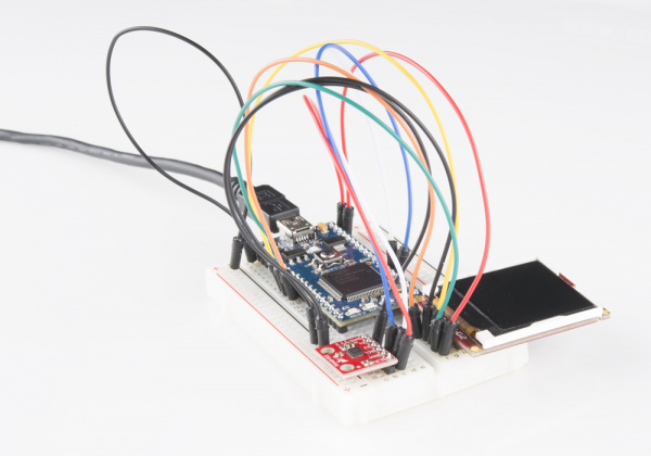
Using the graphic LCD from the previous tutorial, we will connect a sensor to add an interactive component to our project. We can use an MMA8452Q 3-axis accelerometer to move a ball around the screen for a cool demo.
Suggested Reading
The Circuit
This circuit can be made with parts in the SparkFun mbed Starter Kit. Also, keep in mind that the LPC1768 box contains a USB mini-B cable for programming and power.
Parts List
To follow this experiment, you would will need the following materials if you did not order the SparkFun mbed starter kit. You may not need everything though depending on what you have. Add it to your cart, read through the guide, and adjust the cart as necessary.
Schematic
Connections
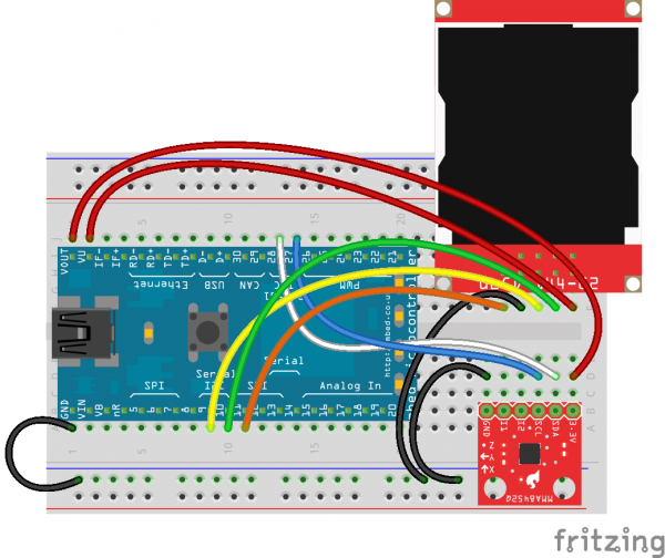
Connect the LPC1768 to the LCD and accelerometer in the following fashion. Note that the LCD uses the same connections as in Part 3.
Fritzing Diagram
Hookup Table
Place the LPC1768 in a breadboard with pin VOUT in position i1 and pin 20 in position b20.
Connect the rest of the components as follows:
| Component | Breadboard | ||||
|---|---|---|---|---|---|
| uLCD-144-G2* | h26 (RES) | h27 (GND) | h28 (RX) | h29 (TX) | h30 (+5V) |
| MMA8452* | b25 (GND) | b28 (SCL) | b29 (SDA) | b30 (3.3V) | |
| Jumper Wire | j2 | f30 | |||
| Jumper Wire | a1 | ( - ) | |||
| Jumper Wire | a9 | f28 | |||
| Jumper Wire | a10 | f29 | |||
| Jumper Wire | a11 | f26 | |||
| Jumper Wire | ( - ) | f27 | |||
| Jumper Wire | ( - ) | d25 | |||
| Jumper Wire | j14 | d28 | |||
| Jumper Wire | j13 | d29 | |||
| Jumper Wire | j1 | d30 | |||
* Pins not listed are not used.
The Code
We will be building on the previous tutorial. In addition to importing an mbed library from the Cookbook for the LCD, we will be building our own library for the MMA8452Q accelerometer.
Libraries
Navigate to the developer.mbed.org, login, and navigate to your Compiler.
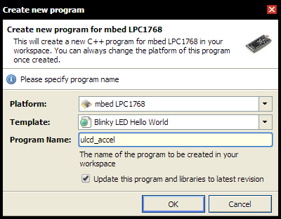
Right-click on "My Programs" and create a new program.
Give your program an appropriate name (such as "ulcd_accel"), keep the Template as "Blinky LED Hello World," and click OK.
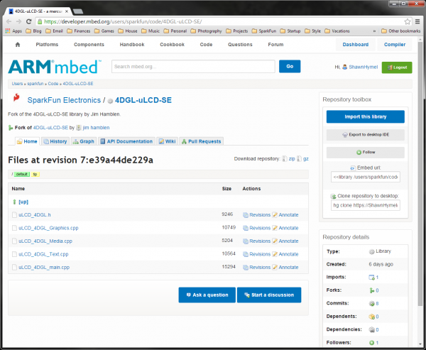
Navigate to the 4DGL-uLCD-SE library page.
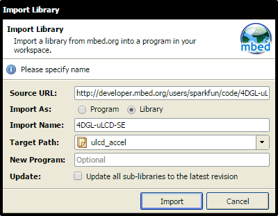
Click “Import this library” on the right side of the page. You will be brought to the mbed Compiler and asked to import the library. For "Target Path," select our "ulcd_accel" project and click "Import."
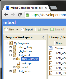
The library should now appear under our project in the Program Workspace.
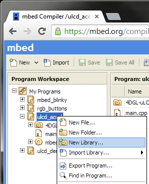
Now, we get to create our own library! Right-click on the program in the left pane and select "New Library..."
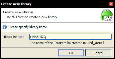
Name your library "MMA8452Q" and click OK.
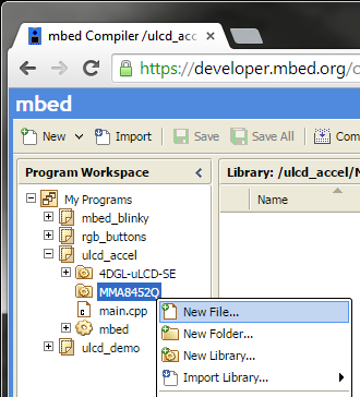
Right-click on the newly created library and select "New File..."
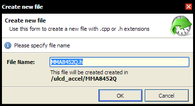
Name your new file "MMA8452Q.h" and click OK.
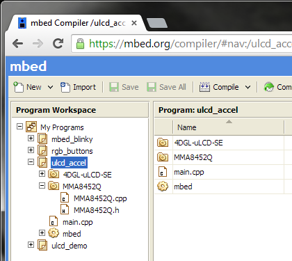
Repeat the same file creation process to make another file: "MMA8452Q.cpp". Your project folder should contain a main.cpp, the mbed library, the 4DGL-uLCD-SE library, and our newly created MMA8452Q library (with our blank .h and .cpp files).
Click on the "MMA8452Q.h" file to open up the blank header (.h) file. Copy the following code into the file.
language:c
// Library for our MMA8452Q 3-axis accelerometer
// Based on the MMA8452Q Arduino Library by Jim Lindblom (SparkFun Electronics)

#ifndef MMA8452Q_H
#define MMA8452Q_H

#include "mbed.h"

// Register definitions
#define REG_STATUS          0x00
#define OUT_X_MSB           0x01
#define OUT_X_LSB           0x02
#define OUT_Y_MSB           0x03
#define OUT_Y_LSB           0x04
#define OUT_Z_MSB           0x05
#define OUT_Z_LSB           0x06
#define REG_WHO_AM_I        0x0D
#define REG_XYZ_DATA_CFG    0x0E
#define REG_CTRL_REG1       0x2A

// WHO_AM_I check
#define FACTORY_ID          0x2A

// Scale definitions
#define SCALE_2G            2
#define SCALE_4G            4
#define SCALE_8G            8

// Data rates
#define ODR_800HZ           0
#define ODR_400HZ           1
#define ODR_200HZ           2
#define ODR_100HZ           3
#define ODR_50HZ            4
#define ODR_12_5HZ          5
#define ODR_6_25HZ          6
#define ODR_1_56HZ          7

// Init values
#define DEFAULT_FSR         SCALE_2G
#define DEFAULT_ODR         ODR_800HZ


// Class declaration
class MMA8452Q
{
    public:
        MMA8452Q(PinName sda, PinName scl, int addr);
        ~MMA8452Q();
        bool init();
        uint8_t available();
        void setScale(uint8_t fsr);
        void setODR(uint8_t odr);
        void standby();
        void active();
        float readX();
        float readY();
        float readZ();
        uint8_t readRegister(uint8_t reg);
        void writeRegister(uint8_t reg, uint8_t data);

    private:
        I2C m_i2c;
        int m_addr;
        int scale;
};

#endif
Click "Save". Note that since we are not compiling our library files right away, we want to save them so we can work on other files. That way, if we lose power or accidentally close our browser, we won't lose our work (don't worry, our library files will get compiled later). Save often!
Click on "MMA8452Q.cpp" to open the blank program (.cpp) file. Copy the following code into the file.
language:c
// Library for our MMA8452Q 3-axis accelerometer
// Based on the MMA8452Q Arduino Library by Jim Lindblom (SparkFun Electronics)

#include "mbed.h"
#include "MMA8452Q.h"

// Constructor
MMA8452Q::MMA8452Q(PinName sda, PinName scl, int addr) : m_i2c(sda, scl), m_addr(addr)
{
    // Initialize members
    scale = DEFAULT_FSR;
}

// Destructor
MMA8452Q::~MMA8452Q()
{

}

// Initialization
bool MMA8452Q::init()
{
    // Check to make sure the chip's ID matches the factory ID
    uint8_t c = readRegister(REG_WHO_AM_I);
    if( c != FACTORY_ID ) {
        return false;
    }

    // Set default scale and data rate
    standby();
    setScale(DEFAULT_FSR);
    setODR(DEFAULT_ODR);
    active();

    return true;
}

// Set the full-scale range for x, y, and z data
void MMA8452Q::setScale(uint8_t fsr)
{
    uint8_t config = readRegister(REG_XYZ_DATA_CFG);
    scale = fsr;
    config &= 0xFC;                     // Mask out FSR bits
    fsr = fsr >> 2;                     // Trick to translate scale to FSR bits
    fsr &= 0x03;                        // Mask out acceptable FSRs
    config |= fsr;                      // Write FSR bits to config byte
    writeRegister(REG_XYZ_DATA_CFG, config);              // Write config back to register
}

// Set the Output Data Rate
void MMA8452Q::setODR(uint8_t odr)
{
    uint8_t ctrl = readRegister(REG_CTRL_REG1);
    ctrl &= 0xCF;                       // Mask out data rate bits
    odr &= 0x07;                        // Mask out acceptable ODRs
    ctrl |= (odr << 3);                 // Write ODR bits to control byte
    writeRegister(REG_CTRL_REG1, ctrl); // Write control back to register
}

// Set accelerometer into standby mode
void MMA8452Q::standby()
{
    uint8_t c = readRegister(REG_CTRL_REG1);
    c &= ~(0x01);                       // Clear bit 0 to go into standby
    writeRegister(REG_CTRL_REG1, c);    // Write back to CONTROL register
}

// Set accelerometer into active mode
void MMA8452Q::active()
{
    uint8_t c = readRegister(REG_CTRL_REG1);
    c |= 0x01;                          // Set bit 0 to go into active mode
    writeRegister(REG_CTRL_REG1, c);    // Write back to CONTROL register
}

// Read X registers
float MMA8452Q::readX()
{
    int16_t x = 0;
    float cx = 0;

    // Read MSB and LSB from X registers
    x = readRegister(OUT_X_MSB);
    x = x << 8;
    x |= readRegister(OUT_X_LSB);
    x = x >> 4;

    // Calculate human readable X
    cx = (float)x / (float)2048 * (float)(scale);

    return cx;
}

// Read Y registers
float MMA8452Q::readY()
{
    int16_t y = 0;
    float cy = 0;

    // Read MSB and LSB from Y registers
    y = readRegister(OUT_Y_MSB);
    y = y << 8;
    y |= readRegister(OUT_Y_LSB);
    y = y >> 4;

    // Calculate human readable Y
    cy = (float)y / (float)2048 * (float)(scale);

    return cy;
}

// Read Z registers
float MMA8452Q::readZ()
{
    int16_t z = 0;
    float cz = 0;

    // Read MSB and LSB from Z registers
    z = readRegister(OUT_Z_MSB);
    z = z << 8;
    z |= readRegister(OUT_Z_LSB);
    z = z >> 4;

    // Calculate human readable Z
    cz = (float)z / (float)2048 * (float)(scale);

    return cz;
}

// Raw read register over I2C
uint8_t MMA8452Q::readRegister(uint8_t reg)
{
    uint8_t dev_addr;
    uint8_t data;

    // I2C address are bits [6..1] in the transmitted byte, so we shift by 1
    dev_addr = m_addr << 1;

    // Write device address with a trailing 'write' bit
    m_i2c.start();
    m_i2c.write(dev_addr & 0xFE);

    // Write register address
    m_i2c.write(reg);

    // Write a start bit and device address with a trailing 'read' bit
    m_i2c.start();
    m_i2c.write(dev_addr | 0x01);

    // Read single byte from I2C device
    data = m_i2c.read(0);
    m_i2c.stop();

    return data;
}

// Raw write data to a register over I2C
void MMA8452Q::writeRegister(uint8_t reg, uint8_t data)
{
    uint8_t dev_addr;

    // I2C address are bits [6..1] in the transmitted byte, so we shift by 1
    dev_addr = m_addr << 1;

    // Write device address with a trailing 'write' bit
    m_i2c.start();
    m_i2c.write(dev_addr & 0xFE);

    // Write register address
    m_i2c.write(reg);

    // Write the data to the register
    m_i2c.write(data);
    m_i2c.stop();
}
Click "Save".
And that's it! We just created our very first library in mbed. Because the library is contained within our project, everything is automatically linked at compile time. We just need to write #include "MMA8452Q.h" in our main program to use the MMA8452Q accerlerometer functions.
Program
Click on "main.cpp" under our "ulcd-accel" project to open up our main program file. Because we selected the "Blinky" template, there will be some code in the file already. Go ahead and delete everything in "main.cpp". Copy and paste in the following code.
language:c
// Demo for the uLCD-144-G2 and MMA8452Q 3-axis accelerometer

#include "mbed.h"
#include "MMA8452Q.h"
#include "uLCD_4DGL.h"

// Graphic LCD - TX, RX, and RES pins
uLCD_4DGL uLCD(p9,p10,p11);

// Accelerometer - SDA, SCL, and I2C address
MMA8452Q accel(p28, p27, 0x1D);

int main() {

    // Initialize uLCD
    uLCD.baudrate(115200);
    uLCD.background_color(BLACK);
    uLCD.cls();

    // Initialize accelerometer
    accel.init();

    // Initial parameters for the circle
    float x = 64;
    float y = 64;
    int radius = 4;
    int speed = 4;

    // Make a ball "fall" in direction of accelerometer
    while (1) {

        // Draw a red circle
        uLCD.filled_circle((int)x, (int)y, radius, RED);

        // Wait before erasing old circle
        wait(0.02);         // In seconds

        // Erase old circle
        uLCD.filled_circle((int)x, (int)y, radius, BLACK);

        // Move circle. IMPORTANT! Notice how we adjust for sensor orientation!
        x -= (speed * accel.readY());
        y -= (speed * accel.readX());

        // Make circle sit on edges
        if ( x <= radius + 1 ) {
            x = radius + 1;
        } else if ( x >= 126 - radius ) {
            x = 126 - radius;
        }
        if ( y <= radius + 1 ) {
            y = radius + 1;
        } else if ( y >= 126 - radius ) {
            y = 126 - radius;
        }
    }
}
Run
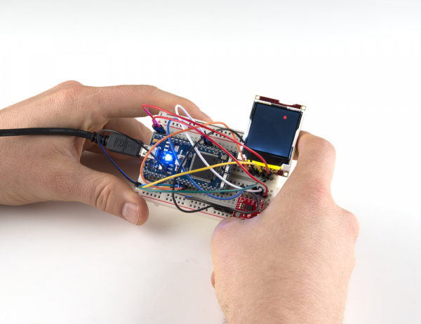
Compile the program and copy the downloaded file to the mbed. Press the mbed's restart button to see the LCD display a little red ball. Pick up the breadboard and tilt it in different directions. You should see the ball start to move around!
Concepts
We touched on a few important concepts in this tutorial that you may want to understand.
I2C
I2C (or "Inter-Integrated Circuit") is a communications protocol built by Philips in the 1980s. As I2C is a bus protocol, it allows for multiple masters and multiple devices to reside on the same bus and relies on addresses to communicate to specific devices. In our example, we used mbed's I2C library to talk to the accelerometer. To read more about the history of I2C, see this Wikipedia article.
Libraries
In the last tutorial, we imported an existing library. In this tutorial, we created a new library to make accessing the accelerometer easier. If you feel that you have a solid, well documented library that you want to share with others, read through mbed's Collaboration guide and specifically, how to write and publish a library.
Header Files
When we made our library, we created two files: a .h file and a .cpp file. The .h file is known as a header file. The header file contains declarations (variables, functions, classes, etc.) for other files in the program to use.
In our main file (main.cpp), we include all of the declarations from the header file (MMA8452Q.h) with the statement
language:c
#include "MMA8452Q.h"
This, in effect, copies everything from the header file to the #include line.
You will also notice that we included the same header file in the MMA8452Q.cpp file. We declare all of our classes, functions, and variables in the header file and define them in the .cpp file (read about the difference between declare and define).
When we compile our program, the compiler sees that we have declared the MMA8452Q class in the included header file, so we can use it in our main program. It will also compile the MMA8452Q.cpp file into an object file.
During the linking phase, the object files are combined into a single executable that is downloaded to your computer as a .bin file.
Floating Point
If you are carefully reviewing the example code, you might have noticed the keyword "float." If you have never dealt with floating point numbers, you might want to read up on how they work. Kip Irvine provides a great floating point tutorial. If you are interested in the history of floating point, see this Wikipedia article.
Going Further
We made an accelerometer do some cool stuff on a graphical display. If you are following the tutorials in order, you will need the LCD for one more!
Beyond the Tutorial
- Can you make a digital bubble level? (Hint: think about how a bubble works and adjust how we move the circle)
- Can you make the ball bounce off the sides? (Hint: look at how we make the ball "sit on edges" and make it bounce instead)
- Can you make a basic ball-in-a-maze game? (Hint: look at how we draw shapes with the LCD library and how to make the ball sit on edges)
Digging Deeper
- Official I2C Primer
- Read the actual I2C Specification (if you're looking for a cure for insomnia)
- Look into how someone else did an MMA8452 library
