Actobotics Basic Differential Platform
 Improvised Dynamics
Build Overview
Introduction
The basic differential bot is a seed platform to help you get started making Actobotics-based robots. This tutorial will go over the basics for building this platform out of Actobotics mechanical parts, available at SparkFun. Control electronics will be covered in some detail but are not the primrary focus of this tutorial, The wishlist contains the parts to build an almost-ready-to-drive vehicle. From here, you can add any sensors or mechanisms you like, or customize the layout for your own unique design.
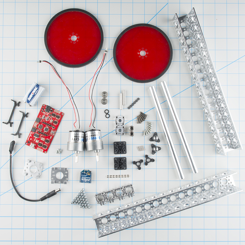
Required Materials
Here is a list of parts used to build this platform. Feel free to mix and match or completely remix this list for your own robot needs.
Required Tools
- 7/64” Hex Key - Use with #6-32 socket head cap screws
- 3/32” Hex Key - Use with set screws in hubs and shaft couplers
- #1 Philips Screwdriver - Use with M3 pan-head screws
- 7/32” or 5.5mm Open-Ended wrench - Use with M3 nuts
- Soldering Iron - Use to attach wires to DC motor leads
- Modeling Knife - Helpful with removing plastic Tamiya parts from the sprue
- Side Cutters - Helpful with removing plastic Tamiya parts from the sprue
- Needle Nose Pliers - Helpful with removing plastic Tamiya parts from the sprue
Additional Supplies
Suggested Reading
This is intended to be an elementary build with no background knowlege required, however, the following links may help you get better acquainted with the concepts in this tutorial.
Hardware Assembly
Ball Casters
The first assembly is the Tamiya Ball caster. Follow the included instructions for the 37mm layout.
Drive Axle Assembly
The next assemblies are the left and right axle.
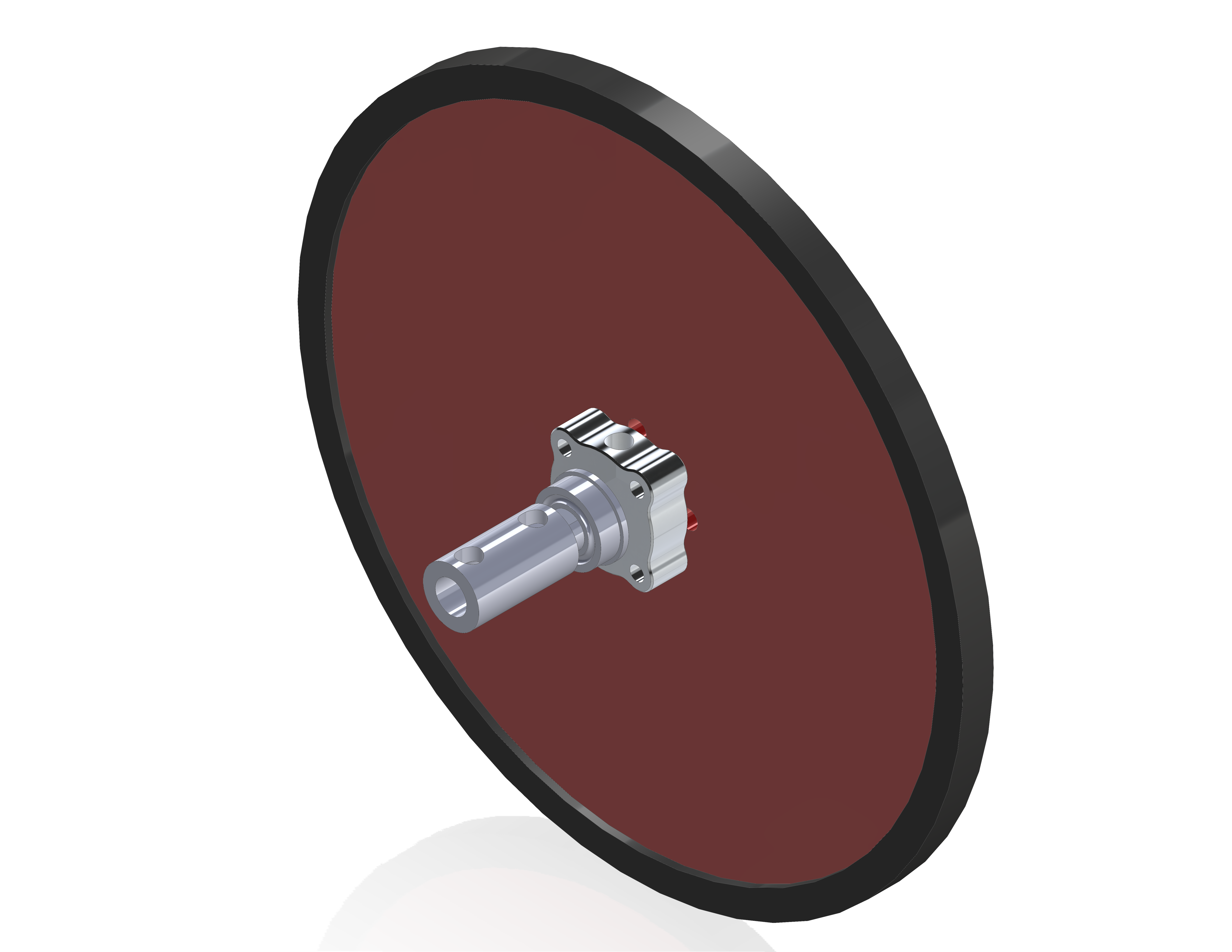
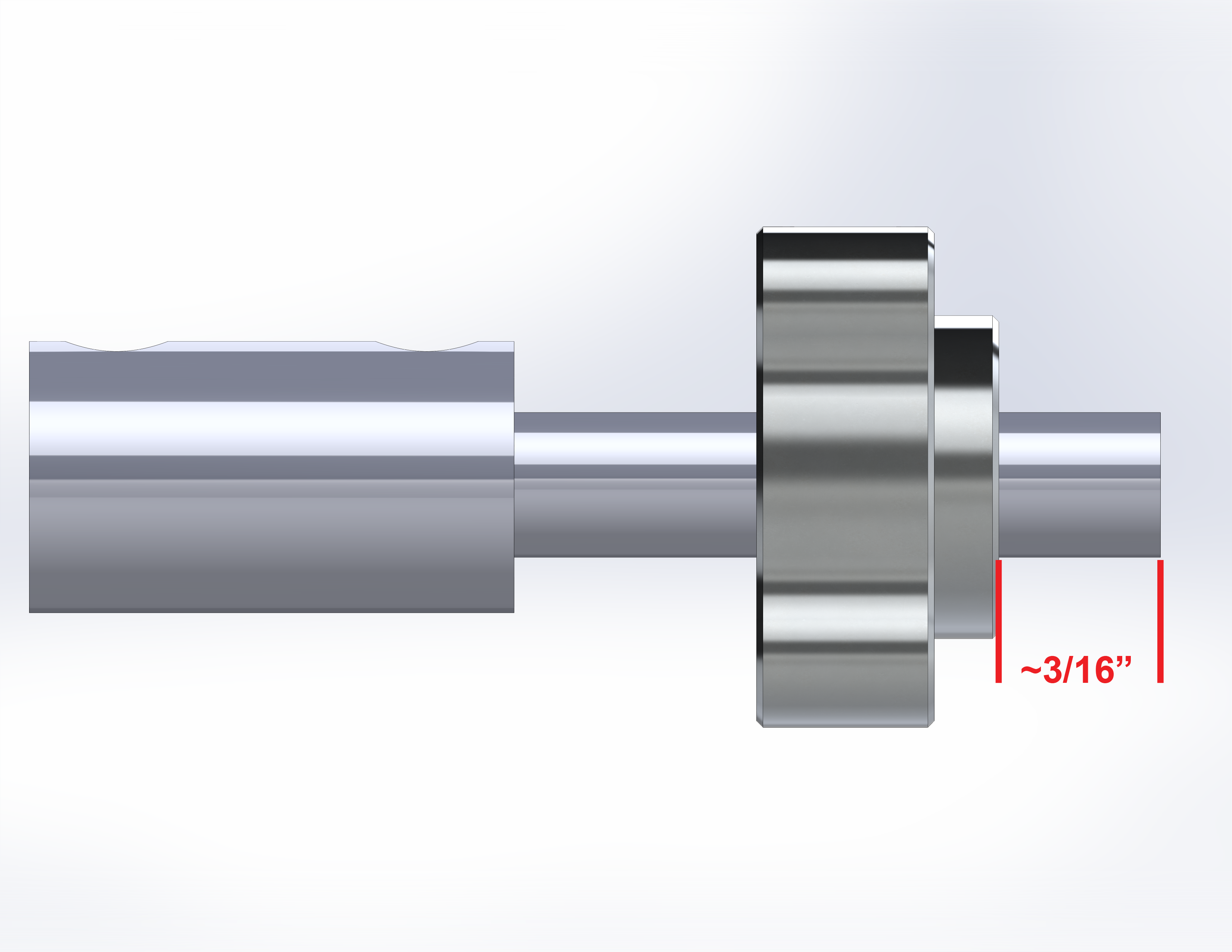
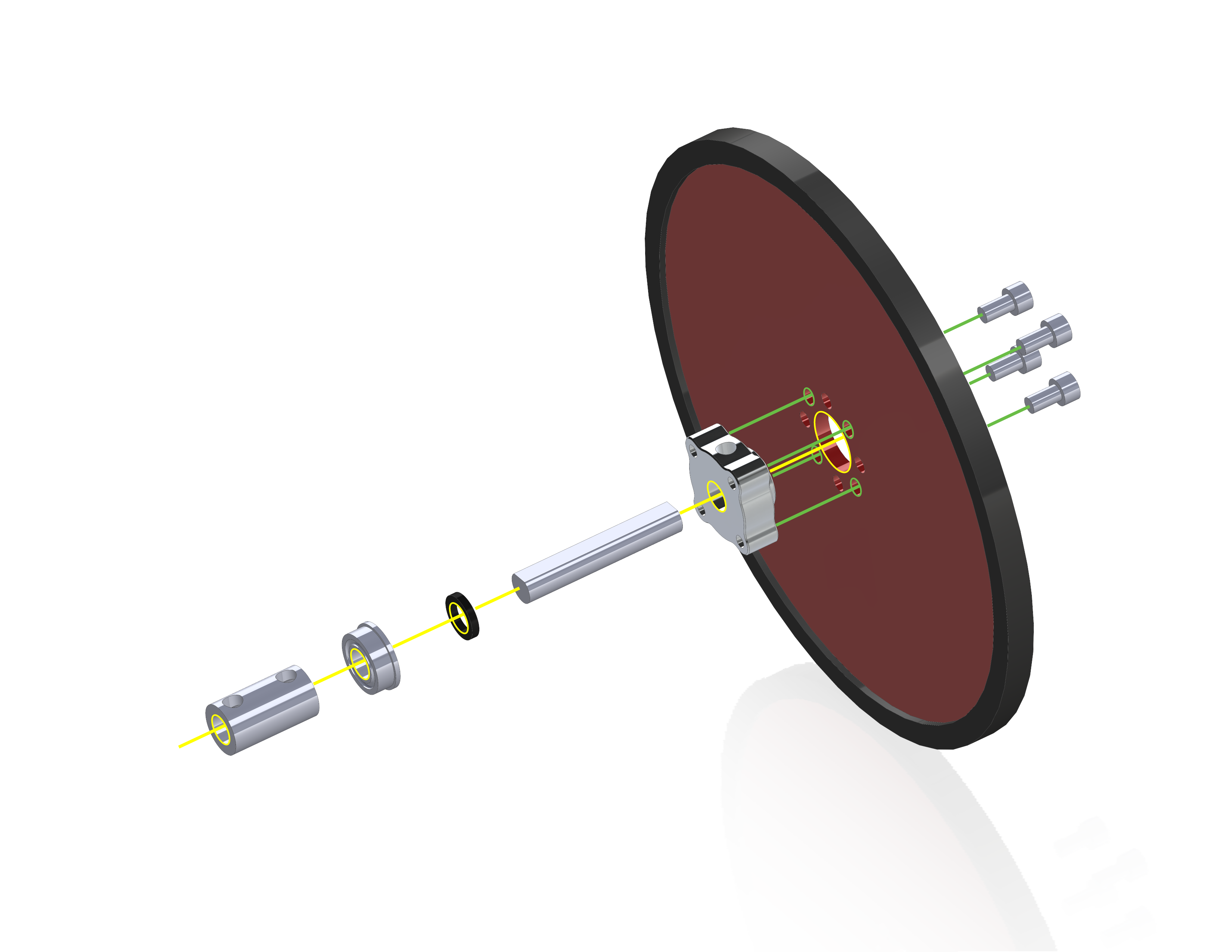
These are identical, so repeat this step for the second side. Attach the large rubber tire to the edge of the precision disc wheel. Then attach the ¼” set-screw hub to the wheel with the raised section of the hub inserted into the center hole of the wheel. Secure the wheel to the hub using four #6-32x ¼” screws. Next insert the D-shaft through the set screw hub, such that the flat side of the shaft is facing the set screw.
Place the shaft so that about 3/16” is coming out the wheel side of the hub, then tighten the set screw in the hub.
Once the shaft is in place, slide one shaft spacer over the shaft on the hub side, followed by one flanged bearing. Orient the bearing so the flange is on the hub side, next to the spacer. Finally add the shaft coupler by inserting the shaft into the ¼” side (it won’t go into the 6mm side). Again, align the set screw with the flat of the D-shaft and tighten. Repeat for the opposing side.
Motor Mounts
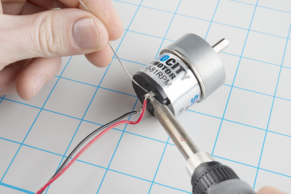
With the axles done, solder wires to the motor leads. Be sure to note the polarity with regard to your wire color.
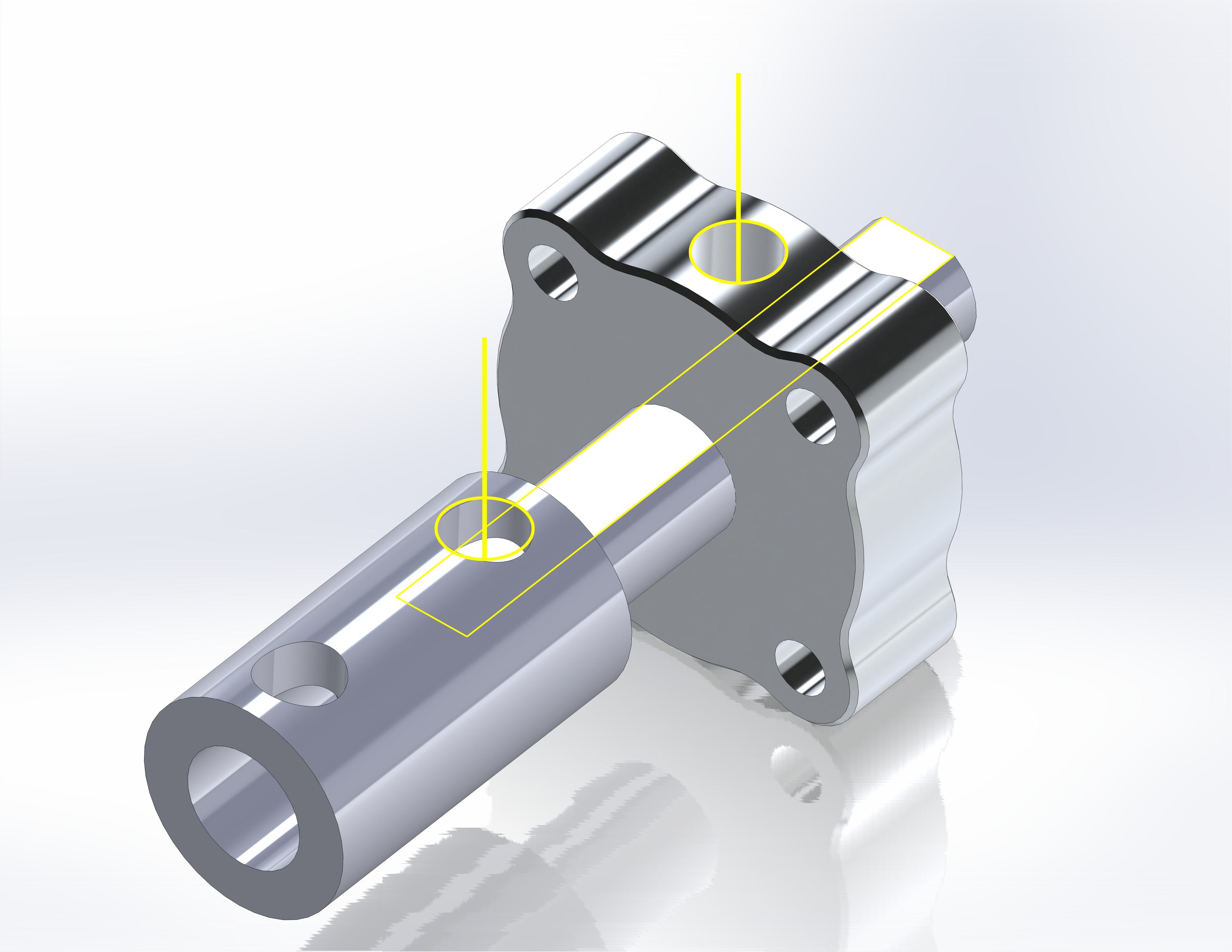
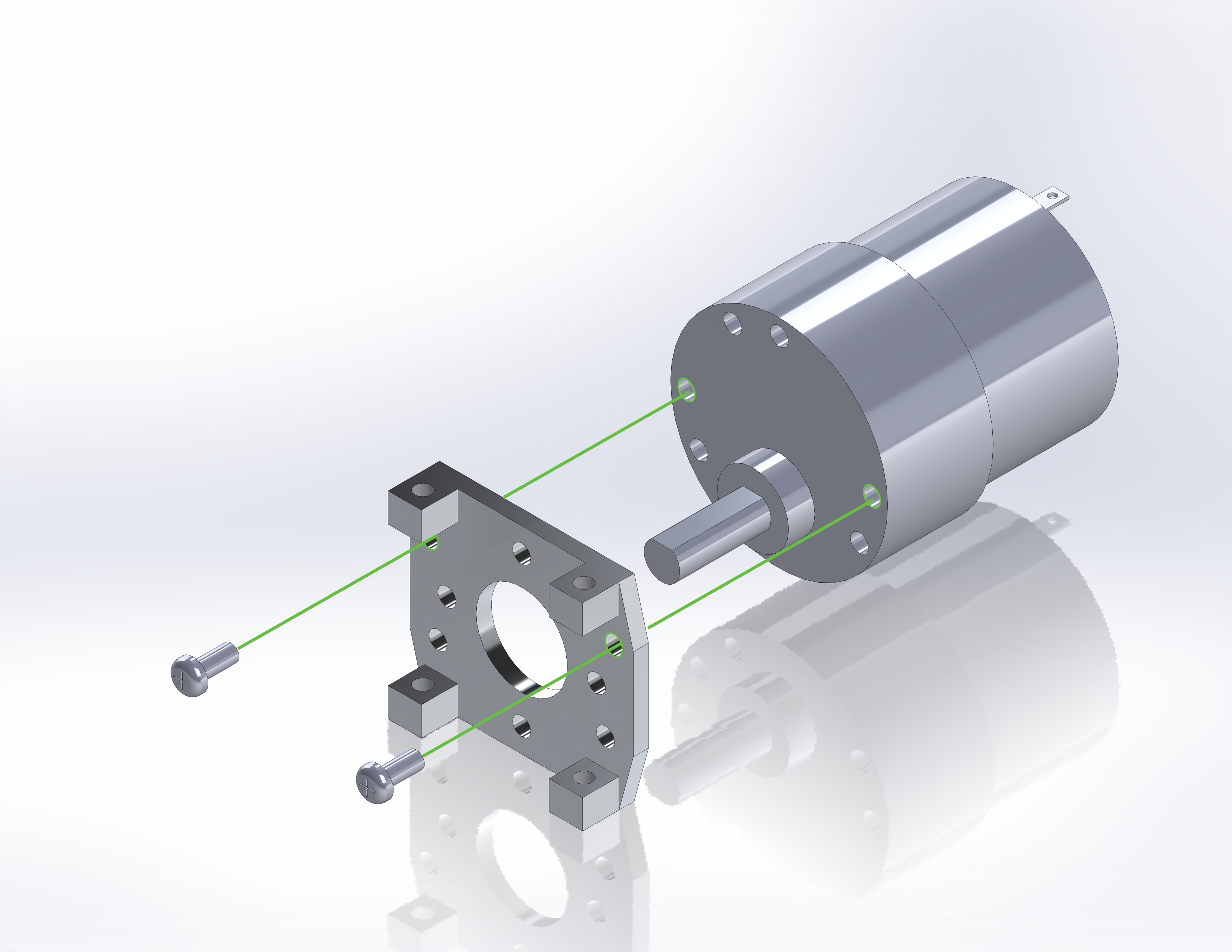
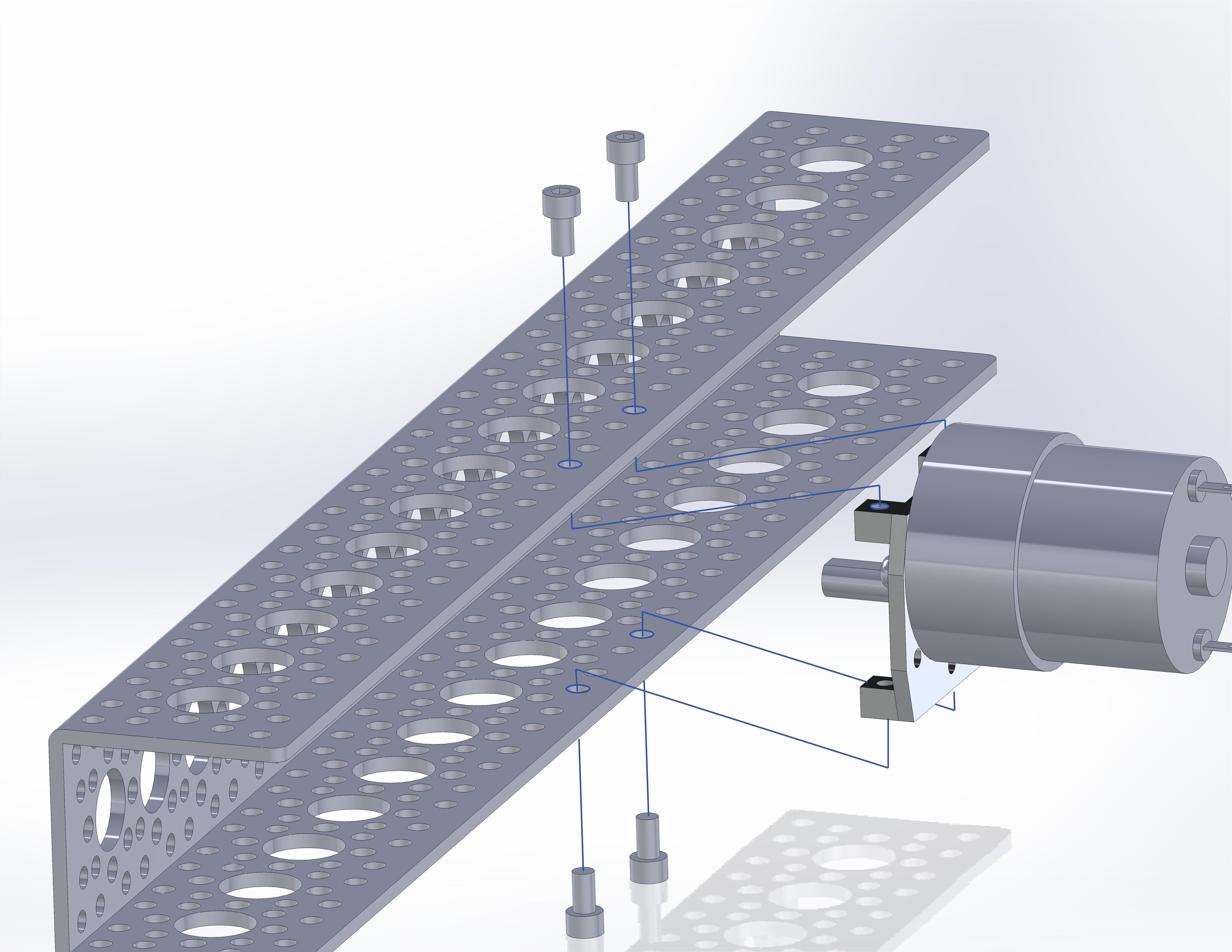
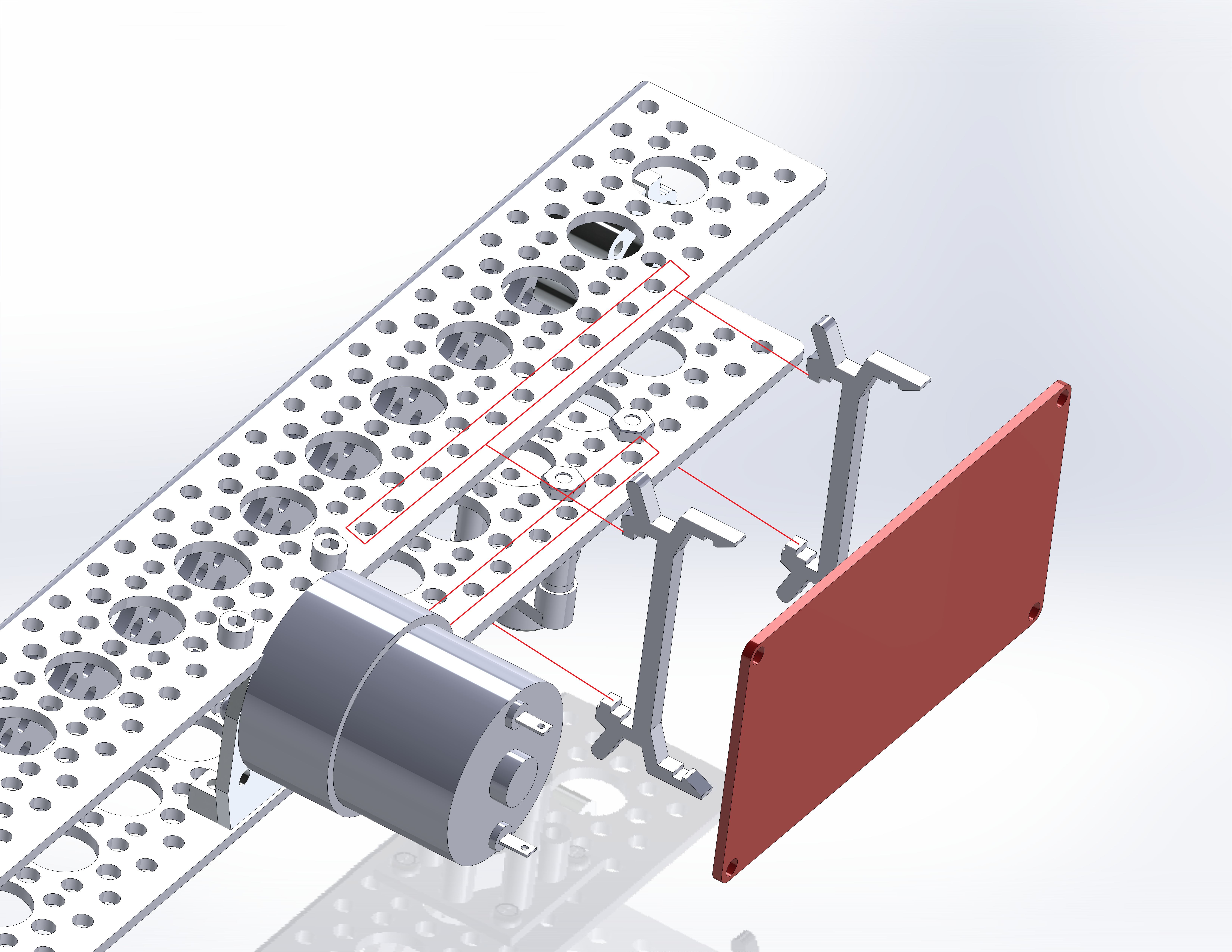
Next, add the motor to the motor mount.
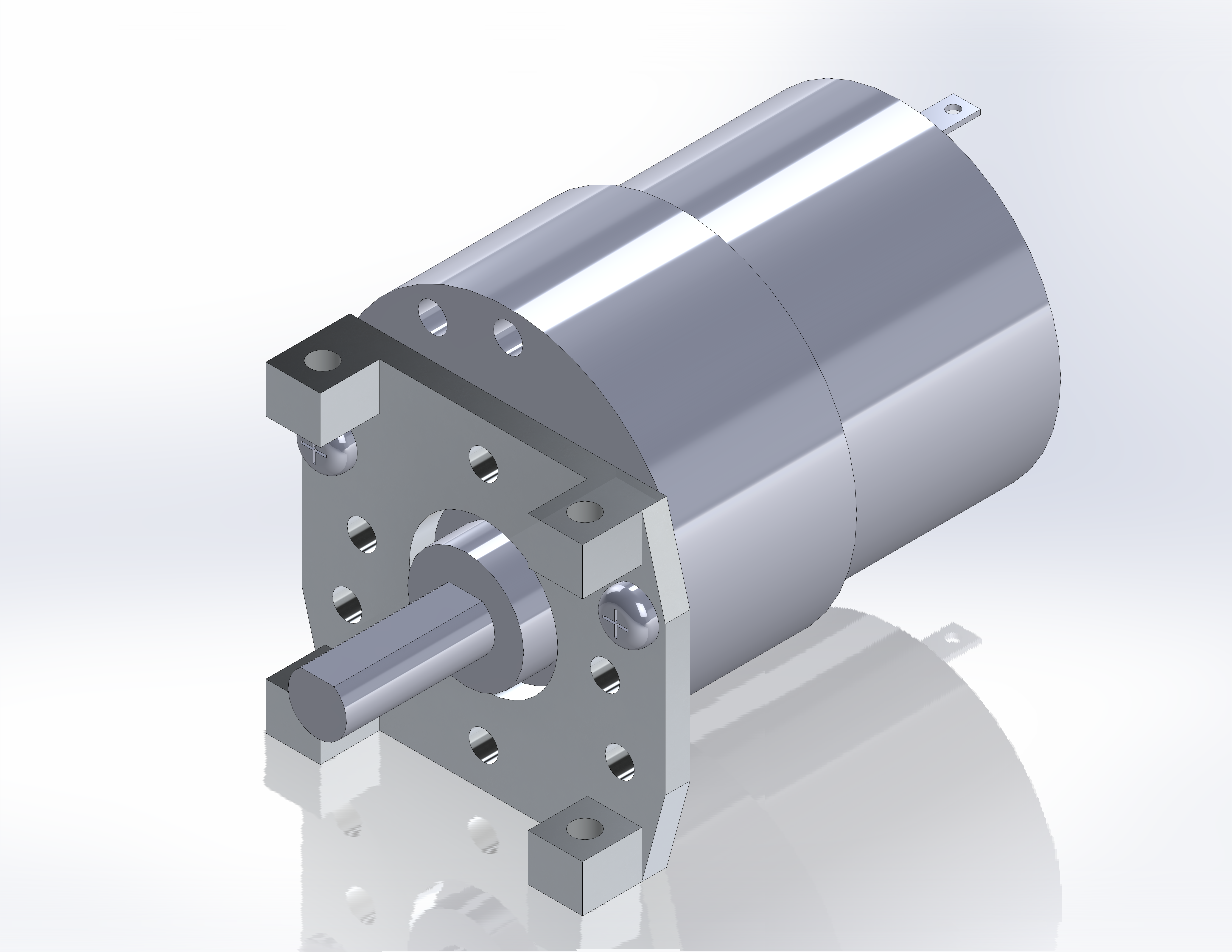
Holding the motor with the output shaft facing you, and oriented at 6:00, locate the holes at 3:00 and 9:00.
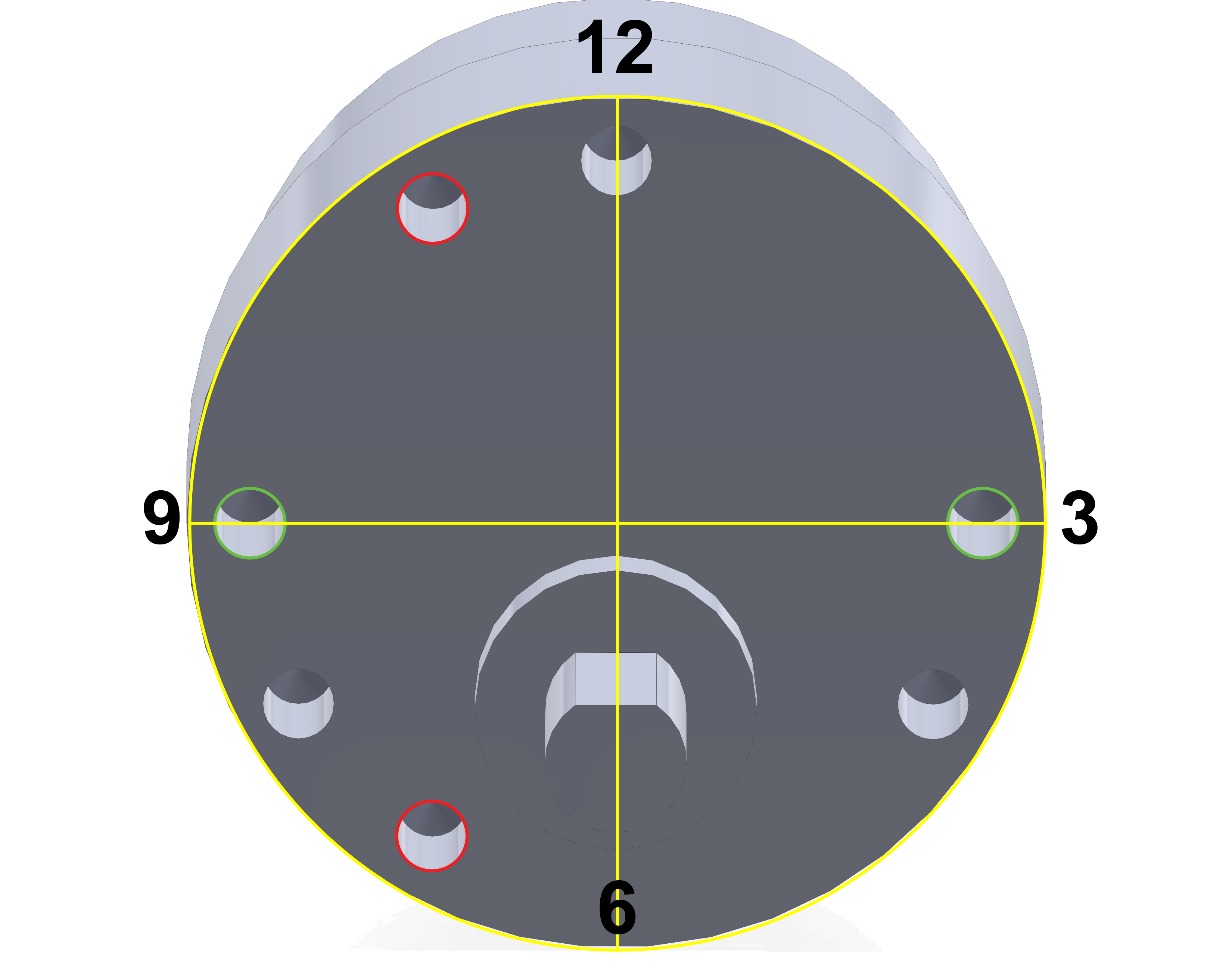
These holes will align with the holes in the motor mount.

Use the holes labelled ‘4’ to align with the motor. Secure with the provided M3 screws. Repeat for the opposing side.
Rail Assembly
With the sub-assemblies complete, we can proceed with building the left and right rails. The channels are the structural backbone of the vehicle so the sub assemblies will be added directly to them.
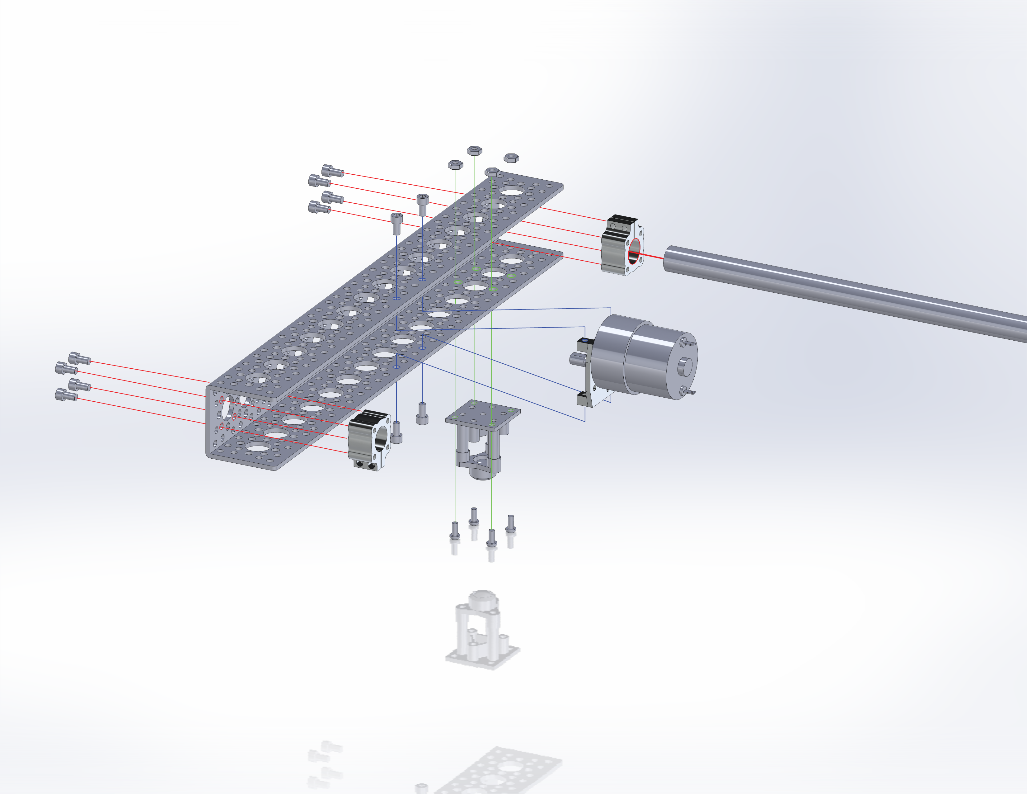
Start by adding a completed caster to the channel in the location shown and secure with four M3x10mm screws and nuts included in the ball caster kit.
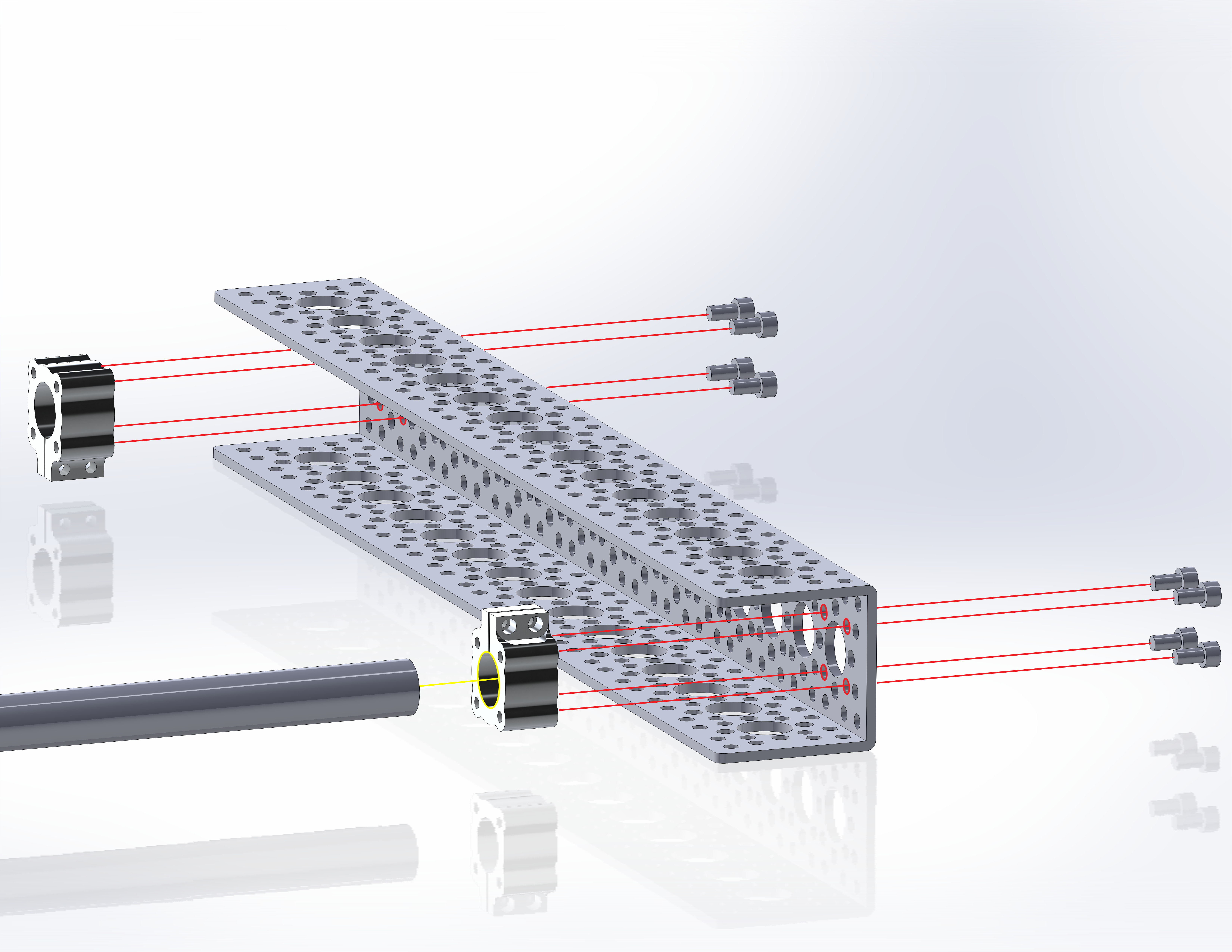
Next add the two #6-32 clamping screws provided with the tube clamps, but do not tighten. Add the clamps in the indicated locations at the ends of the channels. Orient the clamps so that the clamping screw heads are accessible from the ends of the channels. Secure each clamp with four #6-32 screws. Once secure, insert a ½” tube to the clamp near the caster and tighten the clamping screws to lock the rotation of the tube.
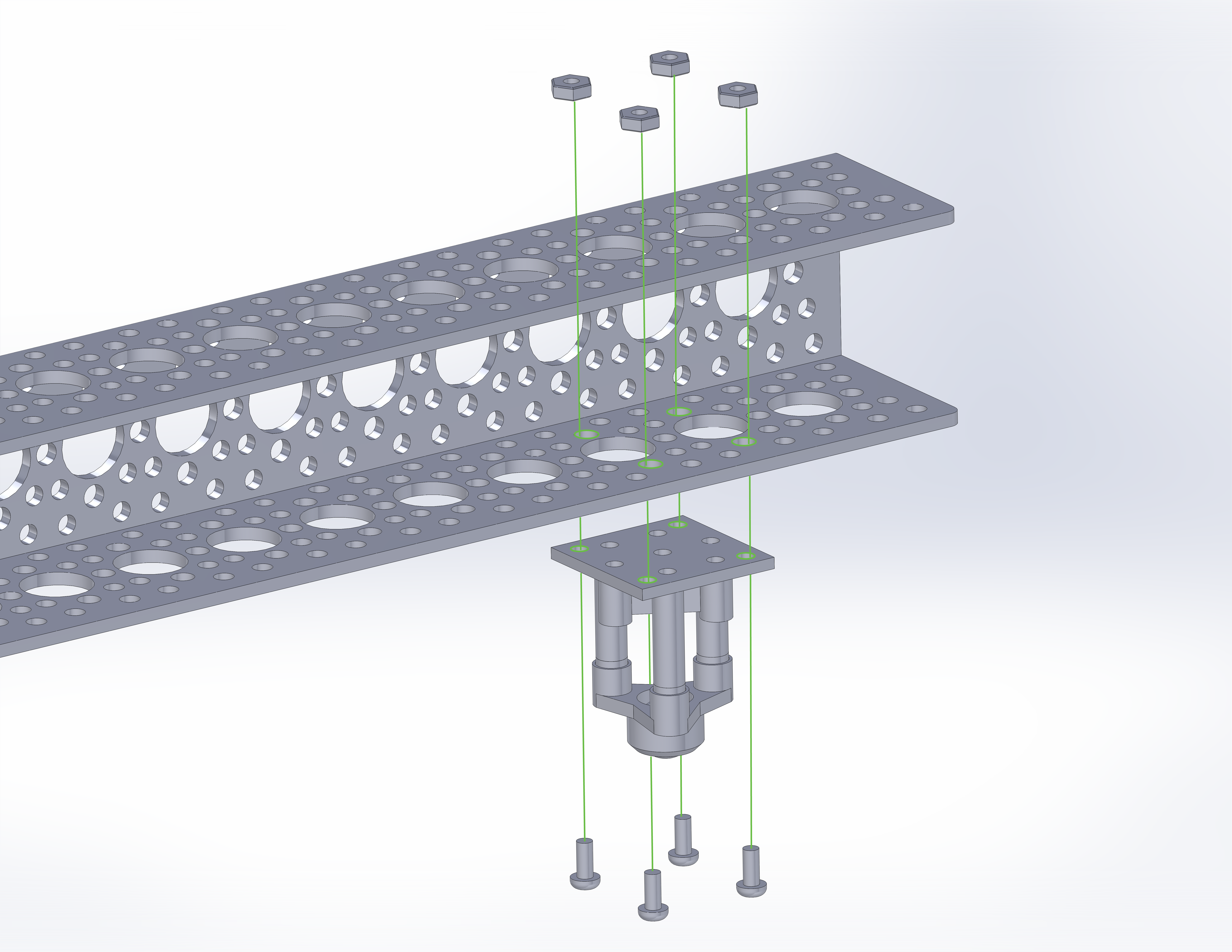
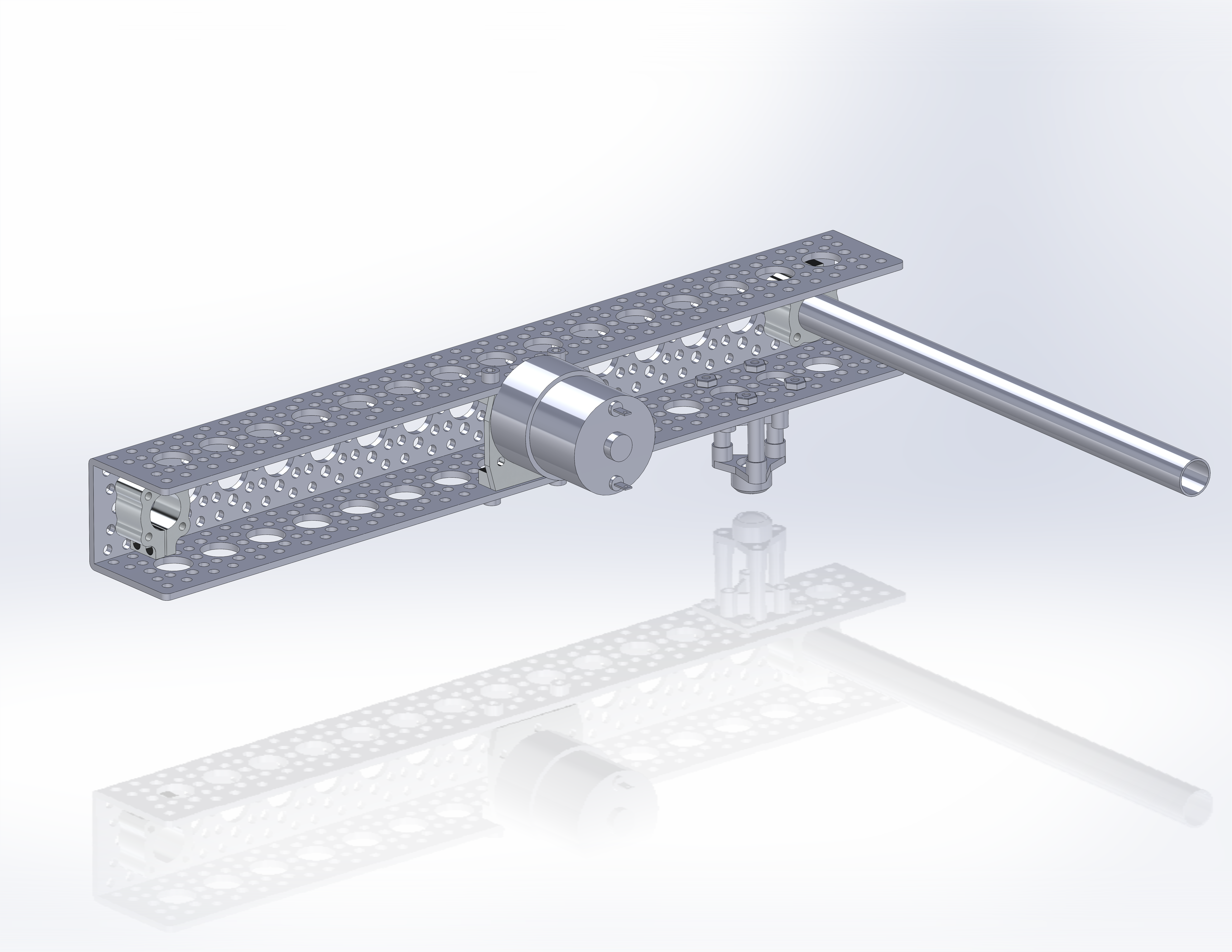
Finally, add the motor/mount assembly to the center of the channel. The motor should sit in the “up” position away from the casters. Secure the assembly with four #6-32 screws.
Repeat for the opposing side.
Final Mechanical Assembly
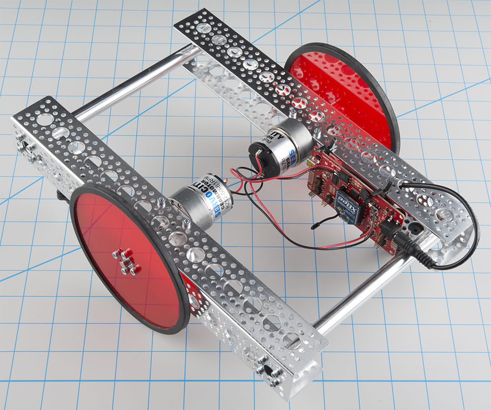
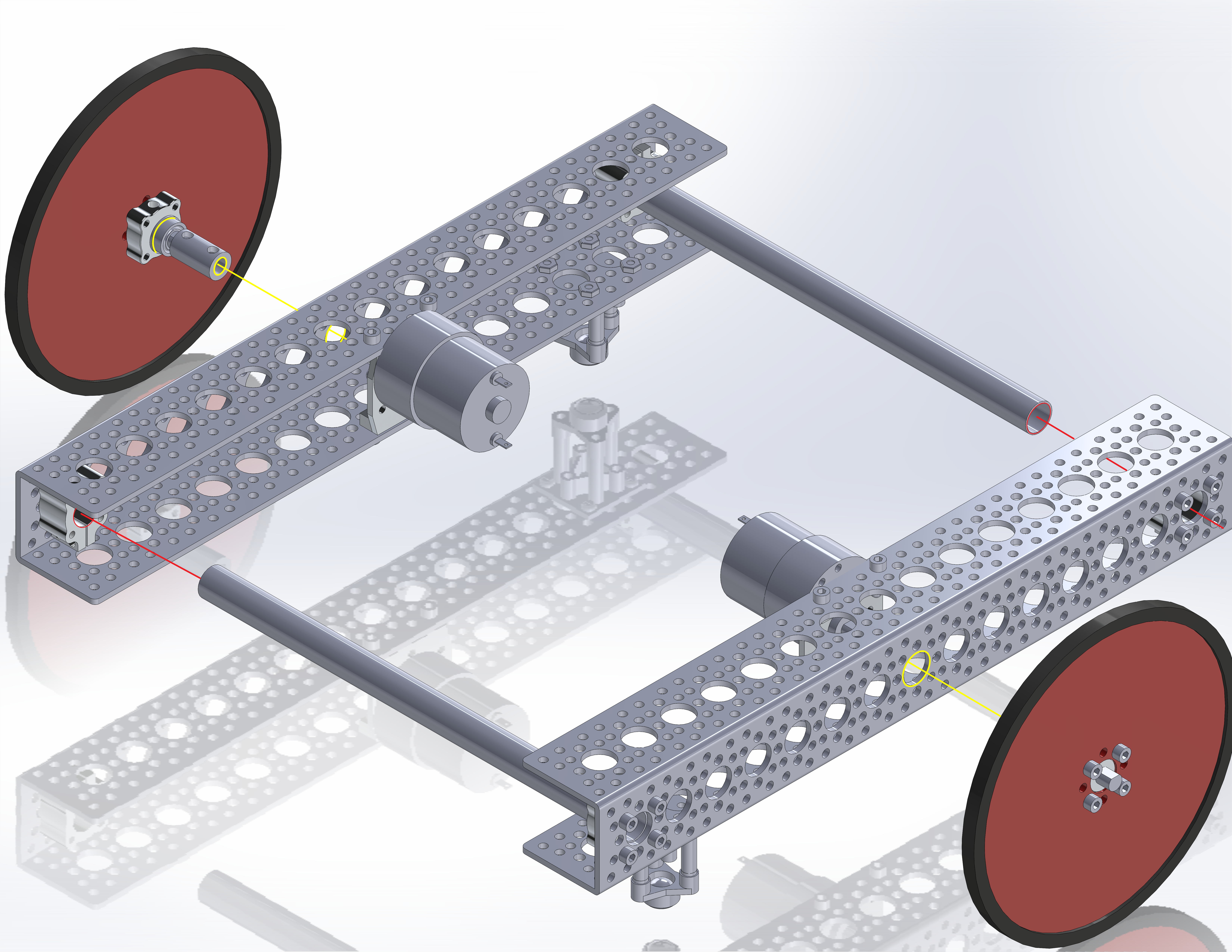
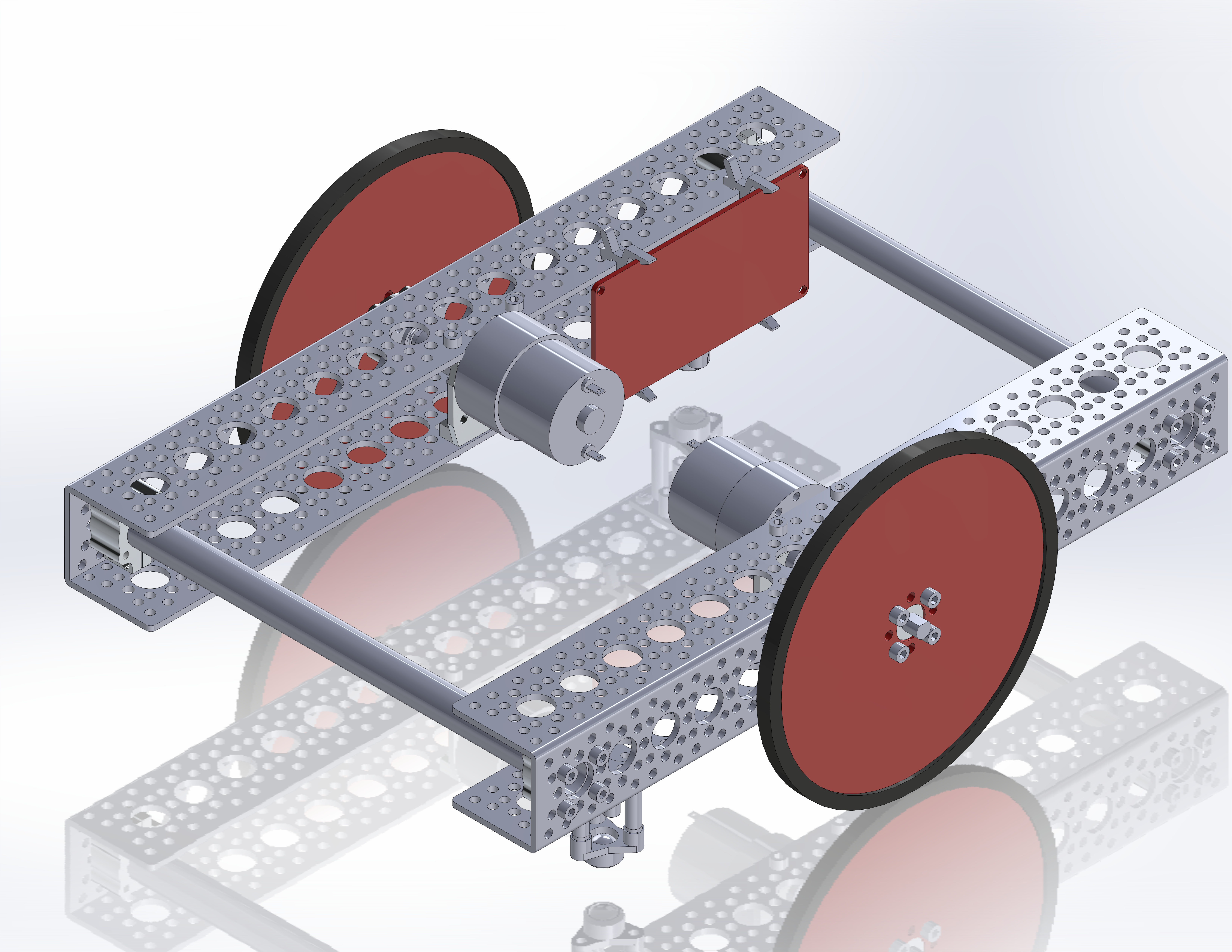
With the rails complete, add them together by inserting the free ends of the tubes into the open tube clamps. Tighten the remaining clamp screws to complete the frame. When finished, it should look like this.

Finally, add the wheel/axle assemblies to the motor shafts. Again, align the set screw on the axle with the flat side of the motor output shaft. Also, be sure that the bearing has fully inserted into the ½” hole in the channel. Tighten the set screw to secure the axle. Repeat for the opposing side. Add a the channel mount clips to one of the rails across the open side of the channel.
The platform is now complete and ready for control electronics. If you are using an Aruduino Uno or Mega, the board can simply snap into the channel mounts. Tuck a battery behind the mounts and connect the motor lead wires to your motor driver shield.
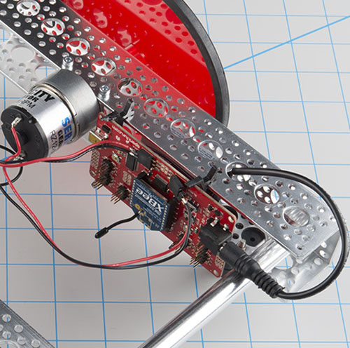
This example uses the Redbot Mainboard to drive the vehicle via XBee radio control. The Redbot board is secured to the channel using two alternate channel mount clips designed for the RedBoard. The design file is available for download here to laser cut a channel bracket for the RedBot Mainboard.
Control System Connection and Setup
If using the Redbot Mainboard, Attach the board as indicated in the previous step. Place the board with the USB facing off the end of the vehicle and the battery jack facing the motor. Attach the lead wires from the motors to the ports on the redbot board. If you are following color convention (i.e. red is positive, black is negative), wire the left motor as indicated on the silkscreen and wire the right motor counter to the silkscreen.
Leave the XBee off the board until after the board has been programed. Set the MOTOR switch to STOP and set the POWER switch to ON.
The control sketch uses single-letter ASCII commands to affect behavior of the vehicle. To program:
- Plug a Mini-B USB cable into the port on the board, and connect it to your computer.
- Let the FTDI populate on your computer, and open your Arduino environment. (If you need help installing FTDI drivers, visit our tutorial).
- Set the Port number to your Redbot, and set the board to Arduino Uno.
- Load the Receiver Code for Redbot sketch onto the board. If the sketch does not compile, please ensure that your Arduino Environment has the RedBot Library installed.
- Set the POWER switch to OFF, unplug the USB from the Redbot, set the MOTOR switch to RUN, set the XBee switch to HW SERIAL, plug in the XBee radio, and attach the 9V Battery.
The vehicle is now complete and ready to drive.
Resources and Going Further
This build is a seed platform. It is designed to be expanded or changed. For additions you could add sensors, a gripper, or any other mechanism you choose. For configuration changes, you could change the placement of the motors and castors, or add motors for a 4-wheel drive vehicle. Additionally, feel free to play around with the control sketch. Modify it to accept your preferred controller, or to be fully autonomous.
For more Actobics fun, check out this other content from SparkFun: