Getting Started with the Autonomous Kit for the Sphero RVR
Troubleshooting Tips
Do you think something is broken? Let's try some of these common troubleshooting tips before looking for technical assistance. This section is written in a hierarchical fashion to make it easier for users to follow from top to bottom. If you know what you are looking for an don't see it right away, don't forget to try a "Google" search; often, someone else has already run into the same issue and may have posted a solution.
First Things First
If you have never tried to troubleshoot a device before, this is a great beginners guide of common points that novices (and even some experienced users) should check.
Replacement Parts
In the event that you lose or break any parts, the components of the kits are linked below. (*Unfortunately, the mounting plate and 3/4" 4-40 standoffs for advanced kit are unavailable at this time.)


Sphero RVR and SDK
For all things related specifically to the Sphero RVR and/or the Sphero SDK, head over to the Sphero SDK website. They have troubleshooting guides for the RVR and SDK software.
If you can't find the information you need in their troubleshooting guides, their community forum is a great place to find and ask for help.
Some quick tips...
- Double check that the UART cable is connected properly and in the correct orientation.
- The login shell or console must be disabled to use the SDK; double check that it is disabled.
- Is the serial switch in the correct position? The tab should be sitting over
RVR. Move serial switch to
RVR. (Click to enlarge) - Don't forget to spawn a shell in the virtual environment (
pipenv shell) to use the example code. - To exit the shell, use Ctrl + D or type
exit.
The Pre-Configured Image
If you have accidentally erased you SD card, it has become corrupted, or you need to start from scratch... the pre-configured image of Raspbian can be downloaded using the button below.
If you have never flashed an image onto an SD card before, check out our SD Cards and Writing Images tutorial.
Remove Overclock
To undo the overclock configuration, modify the config.txt file using sudo nano boot/config.txt. Scroll down to the bottom and under [pi0w] change:
over_voltage=4
force_turbo=1
to:
over_voltage=6
force_turbo=0
(*More information on overclocking can be found on the Raspberry Pi Foundation's website.)
Custom Image
For users looking to build their own image, here are basic instructions. If you know what you are doing then these should be easy to follow. If you don't know what you are doing, download the pre-configured image. (*Assisting customers with building their own custom Raspbian image is beyond the scope of this tutorial and our technical support team).
- Follow the instructions on the Sphero SDK to download and setup the SDK software.
- Download and setup the
RPi_Cam_Web_Interfacecode from the GitHub repository. - Install the
sparkfun-qwiicPython package usingpip3. - Download the SparkFun Autonomous Kit example code from the GitHub repository.
- Move the servo control firmware from the SparkFun Autonomous Kit example code to the
RPi_Cam_Web_Interfacefolder. - Modify the
start.shandstop.shbash scripts to use and terminate the servo control firmware. - Configure the SD card to overclock Raspberry Pi Zero Ws:
- Enable the required interfaces for the Raspberry Pi.
Testing the Hardware
Testing the hardware is a great place to start, refer to the Initial Hardware Tests section in this guide for testing all the hardware included in these kits.
If there something you are trying to do with a specific piece of hardware, go back to the Initial Hardware Tests section to verify it is working with the example code. If the device is working with the example code, then there is possibly an issue with the code you have written. Otherwise, if the device isn't responding properly, users double check if any of the "tricks of the trade" (i.e. tips) below apply.
"Google" It!
Have you tried searching the internet for a solution to your issue? Often with common issues, someone else will have run into the same issue and there will be a few posts on it with solutions, if not workarounds.
(*Search engines like Google are great resources! There are entire forums and resources out there that are dedicated to specifically, supporting the use of the Raspberry Pi and/or Python.)
Weird Characters/Keyboard Map
If you are getting weird characters when typing, double check that the keyboard map is configured properly. You can set the localization and keyboard map using sudo raspi-config.
WiFi
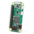
Double check the WiFi network. As mentioned in the Configure the Raspberry Pi section, the Raspberry Pi Zero W supports 2.4GHz 802.11n wireless LAN and is only compatible with 2.4GHz networks. It will not connect to a 5GHz WiFi network.
If you are in an office or school setting, you may be on an enterprise network. Check with your IT network administrator about making sure that you have the necessary permissions and configurations in place to utilize our kit.
If you have multiple Raspberry Pi's on a single network, try powering the rest off and just using the Raspberry Pi you are trying to troubleshoot. This should isolate any bandwidth issues that may occur if you have too many devices connected to the network at once.
Use the WiFi router's network monitoring tools to verify that the Raspberry Pi and the remote computer are on the network.
Try to ping the Raspberry Pi or ssh in. Try using both the IP address and raspberrypi.local methods.
ping <IP Address>ssh <IP Address>ping raspberrypi.localssh pi@raspberrypi.local
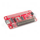
Re-enable the serial console/login shell. Using an SD card reader, add console=serial0,115200 back to the cmdline.txt file on the SD card. Then use the Pi Servo pHat for the headless setup.
- Double check the IP address. Also, try to ping the router, the remote computer, and/or a website to check for any network issues.
ifconfighostname -Iping <IP Address of Remote Computer>ping <IP Address of Router>ping google.com
- Check the
wpa_supplicant.conffile. Do you have the correct country code in?sudo nano /etc/wpa_supplicant/wpa_supplicant.conf
If your Raspberry Pi isn't connecting to the WiFi network, you should re-configure the WiFi. Even if you know you have setup the credentials properly, it was working prviously, or it is on the network... sometimes, resetting the WiFi configuration can help. Users should try both the wpa_supplicant.conf file and raspi-config tool methods.
Camera Focus
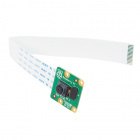
By default the camera lens should be screwed in with the focus set to ∞. Although it is not advisable, the sensor can be refocused.
- This will void any warranty on the product, and you will NOT be able to return the camera module.
- You should avoid this as it can damage the sensor and/or possibly loosen, break, or scratch the lens.
- To refocus the lens, carefully twist the lens at the indentations.
- There are a number of examples online.
Serial Connection
If you are having serial connection issues with the Sphero SDK:
- Double check that the UART cable is connected properly and in the correct orientation.
- The login shell or console must be disabled to use the SDK; double check that it is disabled.
- Is the serial switch in the correct position? The tab should be sitting over
RVR. Move serial switch toRVR. (Click to enlarge)
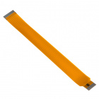
Cable Issue?
Test the serial port on the Raspberry Pi, re-enable the serial console/login shell.
- Using an SD card reader, add
console=serial0,115200back to thecmdline.txtfile on the SD card. - Then use the Pi Servo pHat for the headless setup.
If the serial port on the Pi works, it may be an issue with the UART cable. Try testing for continuity with a multimeter if you have one.
Qwiic Issues
If none of the Qwiic (I2C) devices are responding or you get an IOError, this may be an I2C issue.
- Double check that the I2C bus is enabled on the Raspberry Pi using the
raspi-configtool. - You can also ping the I2C bus using
i2cdetect -y 1. - Test the hardware:
- Double check the Qwiic cables are inserted properly.
- Try testing devices individually following the Initial Hardware Tests section.
- Time to bust out that dusty multimeter. Are they at least getting power?
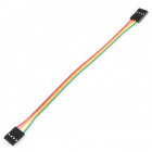
- Try swapping the cable, maybe one of your cables is bad.
- Use a multimeter to double check the continuity on the I2C lines and power.
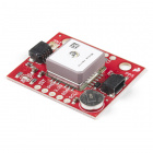
GPS Lock/Accuracy
The GPS needs a view of the sky; check out our GPS Basics tutorial.
- If you are indoors, the GPS satellite signals will not reach the modules.
- If you are near a window, you may get some readings, but they will not be accurate.
- If you are in an urban/city environment, you may have issues with accuracy near tall objects like trees or buildings. This is due to the signal reflection off these objects.
- The triangulation calculation requires precision timing, that is why there are atomic clocks on each satellite. Any slight deviation, including the reflection of a signal, will throw off the position calculation.)
If you see the PPS LED is blinking, but you are not getting any positional data you may not have a lock from enough satellites. The PPS LED doesn't guarantee a positional lock, based on the datasheet, it usually indicates a NMEA sentence was received at some point.
The Titan X1110 receiver is only compatible with GPS and GLONASS satellites.
Servo Inconsistency
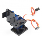
My servo is behaving inconsistently... unfortunately, these are inexpensive servos. (*The Pan/Tilt Bracket Kit costs ~$7. Standard servo costs ~$25-40/each on average.)
- Things like jiggling and slow movements can be expected. This usually occurs because the manufacturing tolerances are low for the potentiometer and gears, used inside. If your servo is acting "all sorts of crazy" when testing with the example code... ok, then you probably have a bad servo; reach out from the technical assistance page.
- Stripping the servo gears and damaging the servo can happen when the servo is forced into a position or manually moved (while powered or connected to the Pi Servo pHat).
- Missing the correct servo horns or screws? This happens from time to time, reach out from the technical assistance page.
- Users can upgrade their pan-tilt servo assembly if they would like to use a more reliable system. Just make sure the replacements have enough space to move, the camera cable is long enough, and that it is compatible with the mounted servo horn (or mounting holes).
VL53L1X
Performance
The ToF sensor does have performance limitations. For example, the sensor FOV, the target properties (i.e. size, color, reflectivity, etc.), and the ambient light all affect the sensor performance and reliability. Check out these related support articles from Garmin:
- How the Garmin LIDAR-Lite Products Work with Reflective Surfaces
- Effects of distance, target size, aspect, and reflectivity on LIDAR-Lite v3/v3HP returned signal strength
I2C Address
The VL53L1X does not permanently store any I2C address changes. On each power up cycle, the sensor reverts to the default I2C address. (*There is no work around... we have already asked the manufacturer. That is why the Qwiic Mux was added to the kit.)
Still Stuck?
Need help?
If your product is not working as you expected or you need technical information, head on over to the SparkFun Technical Assistance page. Otherwise, if you have already tried the troubleshooting tips above, the SparkFun Forums are a great place to find and ask for help. (If this is your first visit, you'll need to create a Forum Account to post questions.)