Getting Started with the Autonomous Kit for the Sphero RVR
Configure the Raspberry Pi
Note: Before assembling the SparkFun autonomous kit for the Sphero RVR, users should configure their Raspberry Pi and then, verify the hardware is working. (These steps can be performed with the kit fully assembled; however, avoid any unnecessary troubleshooting or pitfalls, it is recommended that the instructions be followed as laid in this section, then the hardware verification section, leading up to the Hardware Assembly.)
A pre-configured image of Raspbian Buster (release date: 2019-09-26) is provided in this kit with all the necessary software packages installed. Unfortunately, there are still a few remaining steps to finish configuring the Raspberry Pi so that it can be accessed remotely.
Overclocking Notice: The image is pre-configured to overclock the Raspberry Pi Zero W and was written to only affect Pi Zero Ws. This configuration modifies the hardware; therefore, even if the µSD card is swapped, the Pi Zero W will still be overclocked on the next boot.
Instructions to remove/undo the overclock configuration are included in the troubleshooting section below. However, users should be aware of this modification. It is necessary to overclock the Raspberry Pi Zero in order to minimize the latency/lag on the camera video feed while it is being streamed to the web interface and the Sphero SDK is in operation.
Note: In case users accidentally format their SD card in the excitement to get started, need to start over with a fresh image, or if they just want to build their own image... we have you covered. Our pre-configured image is available in the Troubleshooting section below and we have included some basic instructions to build our image from scratch. Users can also download the pre-configured image by clicking on the button below. (If you have never flashed an image onto an SD card before, check out our SD Cards and Writing Images tutorial.)
Update: The Raspberry Pi Foundation just released their own SD card imager. Check out their blog post.
Setup the WiFi Connection
The one thing we couldn't do is pre-configure the wireless connection for users. The setup process is detailed in the three separate methods below, depending on user's preferences. In order to provide as many options as conveniently possible to setup the WiFi, the serial console (or login shell) was left enabled. However, in order for Sphero's SDK to utilize the serial port (without permissions), the serial console must be disabled; therefore, instructions for disabling the login shell are also detailed for each method in the next section.
WiFi Network Considerations:
- The Raspberry Pi Zero W supports 2.4GHz 802.11n wireless LAN. This is compatible with 802.11b/g/n networks, but only at 2.4GHz; it will not run on a 5GHz WiFi network. If you are a administrator or teacher trying to use this product, be sure to consult your IT department and/or network administrator for assistance with network privileges, compatibility, coverage, etc.
- The web camera interface, in its default configuration, isn't extremely demanding but it does require a fairly decent network speed and bandwidth. It is recommended that users connect their computers or laptops directly to the network (that the Raspberry Pi is setup on) with an Ethernet cable for the best performance in streaming the camera video feed to avoid any latency or lag.
- At all costs, avoid using USB WiFi dongles! (*Trust me, I spent a week tracking down various ghosts only to learn all the issues stemmed from poor performance with the different WiFi dongles I was using.)
- Additionally, it is preferable to avoid using enterprise networks as they can be troublesome to configure and/or troubleshoot issues.
(*More information on configuring the wireless connectivity can be found on the Raspberry Pi Foundation's website.)
SD Card Reader
This is the simplest method as only two files need to be modified; however, it does require a µSD card adpter/reader. Those that are acquainted with the Raspberry Pi most likely already have one stashed somewhere (under a stack of papers?). The only downside to this method is that the IP address for the Raspberry Pi won't be accessible. (*There are options to configure a static IP address, but that is beyond the scope of this tutorial.)
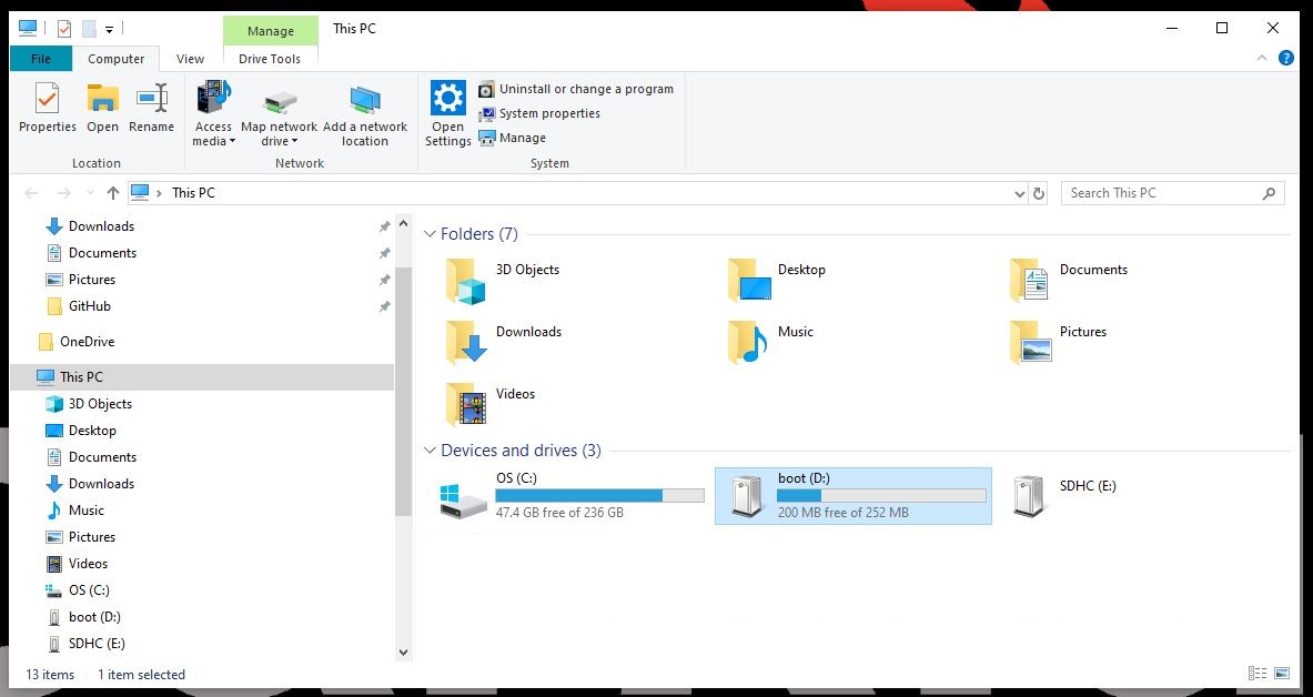
Insert the pre-configured µSD card into the adapter and plug the adapter into a computer. Depending on the computer's OS, the µSD card may appear as several USB drives; however, only the boot drive can be accessed/modified.
WiFi Configuration
To configure the WiFi network interface, the wpa_supplicant.conf file needs to be modified in the boot USB drive of the µSD card. On boot up, the kernel will automatically move the wpa_supplicant.conf file into the appropriate directory of the Linux root file system and use those settings to setup the wireless network. (*On Linux operating systems, the µSD card might get mounted as a disk drive. In that situation, the kernel will probably move the wpa_supplicant.conf file. Therefore, users will need to create a new file.)
boot partition highlighted). (Click to enlarge)Modify the wpa_supplicant.conf file using the default text editor of the operating system. If the file isn't there, you can just create a new one (it should just overwrite the previous file when the kernel moves it).
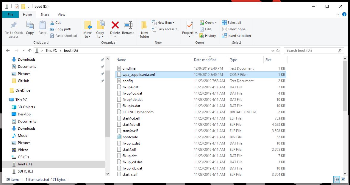
wpa_supplicant.conf file in boot partition of SD card. (Click to enlarge) TextWrangler seems to be the easiest. For Linux, the default system text editor should be fine.For secured networks, the wpa_supplicant.conf file should follow this format:
language:bash
ctrl_interface=DIR=/var/run/wpa_supplicant GROUP=netdev
update_config=1
country=<Insert country code here>

network={
 ssid="<Name of your WiFi>"
 psk="<Password for your WiFi>"
}
- Insert the appropriate ISO code of your country (replace
<Insert country code here>). See Wikipedia for a list of country codes (USis the ISO code for the United States of America). - Insert the credentials for the WiFi network that this kit will be utilized on (replace
<Name of your WiFi>and<Password for your WiFi>). - When creating a
wpa_supplicant.conffile, make sure to utilize the.conffile extension.
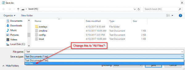
Note: On the Save As... prompt in Notepad for Windows, verify that the file extension type under the Save as type: field is changed from *.txt file to All files. Then you will need to explicitly name the file wpa_supplicant.conf, or Notepad will automatically append the .txt extension to the file name, breaking this functionality.
Another option, is to modify .txt extension of the file. On Mac OS and Linux this variation should be equally simple.
Before unplugging the SD card, move on to the Disabling the Serial Console/Login Shell section below.
(*More information on the wpa_supplicant.conf file can be found on the Raspberry Pi Foundation's website.)
Serial Interface
The second method is to use the serial interface (or login shell). For most users, this will be the primary method to configure the Raspberry Pi without needing to purchase additional equipment. Users will need an additional micro-B USB cable or USB-C cable, but one USB-C cable should already be included with the purchase of a Sphero RVR to charge the battery.
Suggested Tutorials:
For users who have never used a serial terminal and accessed a Raspberry Pi in a headless setup, please review the following tutorials prior to beginning this method. Users will also need to install the CH340C driver on their computers to interface with the Raspberry Pi through a serial terminal.
How to Install CH340 Drivers
Serial Terminal Basics
Headless Raspberry Pi Setup
Using the serial interface (or login shell) allows users to directly interface with the command-line interface (CLI) through another computer's serial terminal. With access to the command-line, users could use a text editor to modify the files mentioned in the previous method; however, that is not the simplest way to configure the Raspberry Pi through the Linux console. A more convenient method is through the raspi-config application, a console-based, configuration tool provides a straightforward way to initially configure a Raspberry Pi.
Users must first ensure that they have the proper CH340C driver installed in order to access the serial interface. (*This allows users' computers to recognize the CH340C USB-to-serial adapter on the Pi Servo pHat.) Users will also need have a serial terminal (emulator) installed on their computer (*the serial monitor of the Arduino IDE will not work in this situation). For instructions on how to install the CH340 driver and how to install a serial terminal on their computer, use the tutorials linked above.
Once the driver and serial terminal are installed on the computer, users will need to assemble the Raspberry Pi Zero W, µSD card, Pi Servo pHat, and USB-C cable.
- Carefully insert the µSD card into the µSD card slot on the Raspberry Pi Zero W.
- Attach the Pi Servo pHat onto the Raspberry Pi Zero W.
- Ensure that the switch on the Pi Servo pHat is moved from
RVRtoUSBto enable serial communication through the USB-C connector. See the Servo pHat Hookup Guide for more details. Move serial switch to
USB. (Click to enlarge) - Insert the USB-C cable into the Pi Servo pHat and plug the other end into a USB port on the computer.
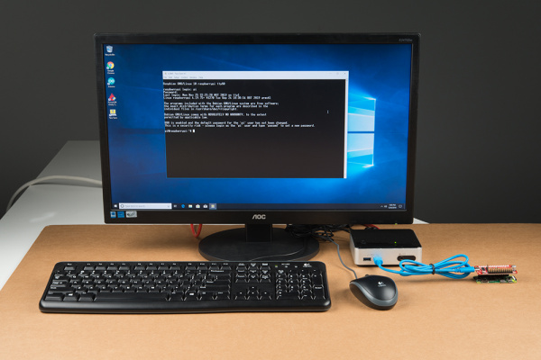 Serial interface setup. (Click to enlarge)

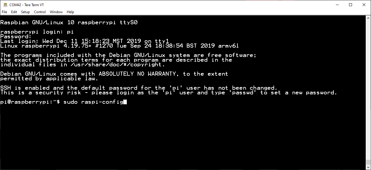
To begin, users will need to access the serial console (login shell) through the serial terminal (emulator) on thier computer. To do this, users should connect to the COM port of the CH340C with a baud rate of 115200. Once connected, press the Enter or Return key to bring up the login promt. (The username and password are the default for the Raspberry Pi: Username = pi and Password = raspberry.)

(*More information on setting up a Raspberry Pi (headless) can be found on the Raspberry Pi Foundation's website.)
WiFi Configuration
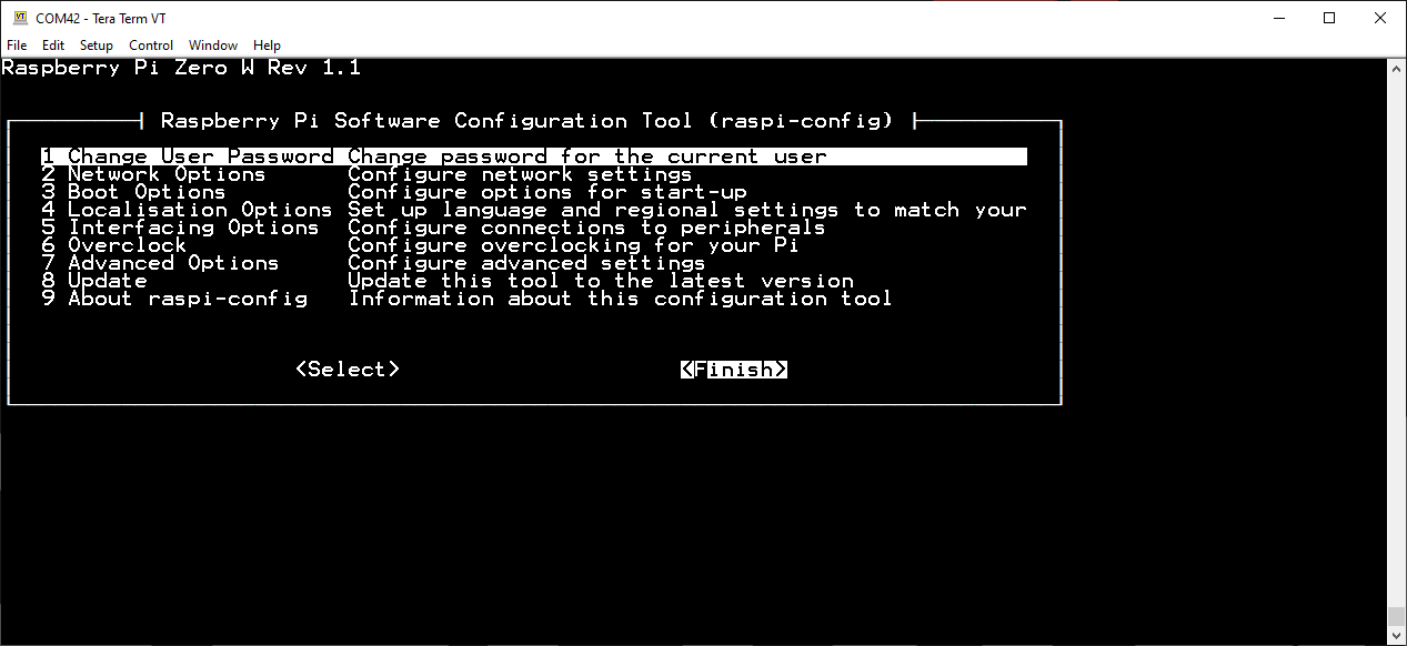
After the Linux console appears, users only need to enter sudo raspi-config to pull up the configuration tool. (Users outside the US will want to configure their localization settings first.)
To configure the WiFi connection, scroll down to 2 Network Options using the arrow keys and hit enter.
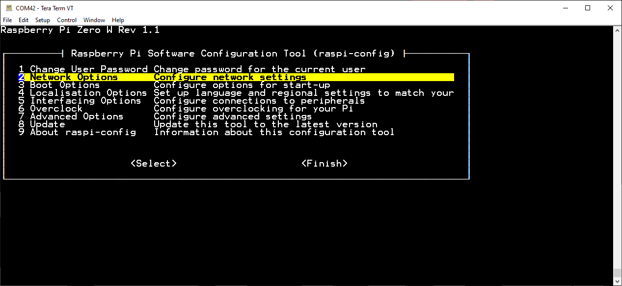
2 Network Options. (Click to enlarge) Then, select N2 Wi-fi.
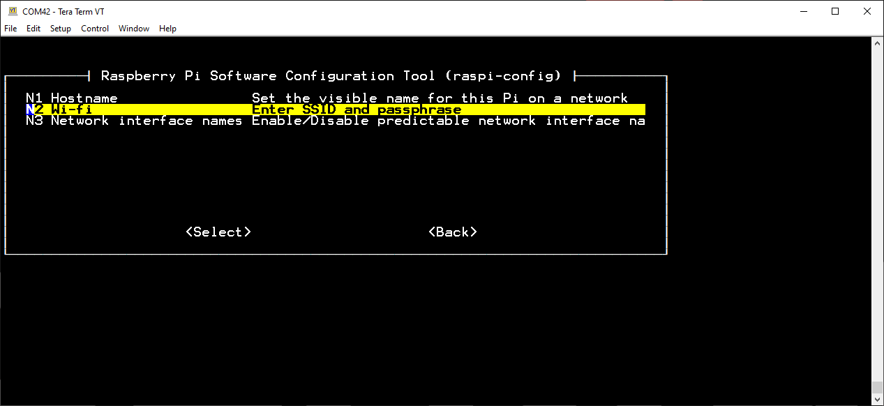
N2 Wi-fi. (Click to enlarge) Once prompted, enter the SSID and passphrase for the wifi network.
Before exiting the raspi-config tool, move on to the Disabling the Serial Console/Login Shell section below.
(*More information on the raspi-config tool can be found on the Raspberry Pi Foundation's website. They also provide additional information for setting up the WiFi via the command line)
Note: For users wanting to edit the configuration file directly, use the following command: sudo nano /etc/wpa_supplicant/wpa_supplicant.conf. (To use a preferred text editor, modify the command accordingly.)
Pixel Desktop
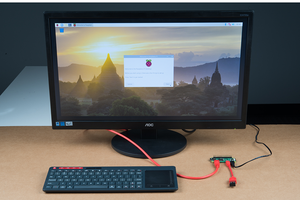
The most user friendly way to configure the Raspberry Pi is with the (one-time) setup wizard and configuration application on the Pixel desktop. However, it is the least convenient of the options as it requires the most additional hardware and setup. Users will need the need the following accessories to access the Pixel desktop:
- Monitor with an HDMI input
- Mini-HDMI to HDMI adapter cable
- micro-B USB OTG cable
- Keyboard and Mouse
- Power Supply
(Users should modify/change the monitor and adapter cable according to the available inputs. Users may also need an additional USB hub.)
Assemble the hardware and accessories as shown below (don't forget to plug the power supply in last).
WiFi Configuration
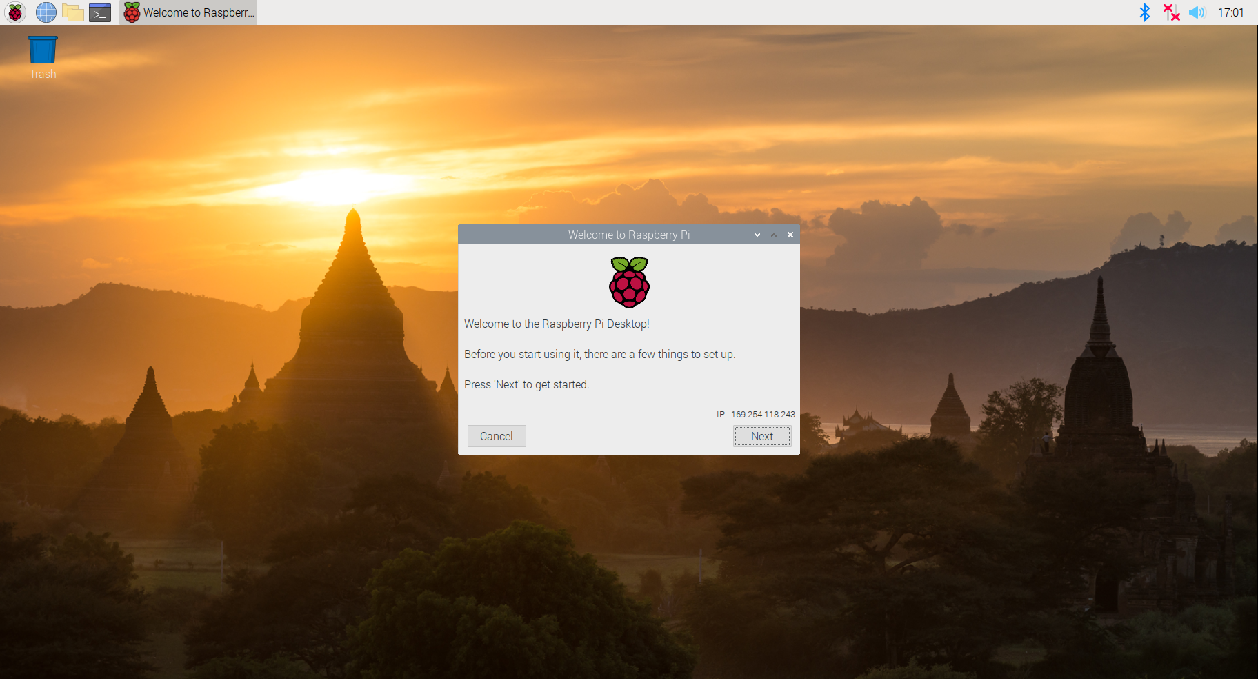
Once the Raspberry Pi has booted to the Linux console, use the startx command to initialize the Pixel desktop and the initial configuration wizard will pop up. Follow the prompts to set-up the WiFi connection. (*The initial configuration wizard is a one-time tool; to bring it up again, use the sudo piwiz command in the Terminal.)
A warning prompt will pop up if SSH is enabled and the Raspberry Pi is still configured with the default user credentials. User can change the user name and password later, it is fine to close this dialog box for now.
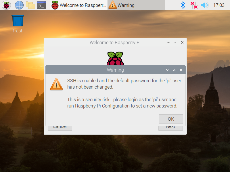
SSH warning pop up. (Click to enlarge)
Users can also setup the WiFi connection through the network icon on the taskbar (*the icon changes based on the network connection type and status).
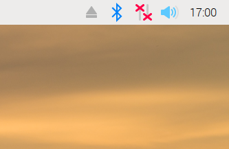
No network connection.
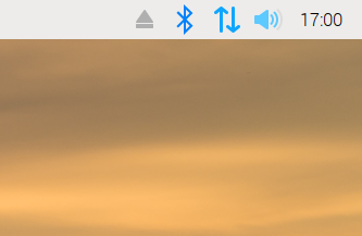
LAN network connection.
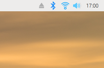
WiFi network connection.
Note: Again, users can use the Terminal application or the Linux console to modify the files directly or access the raspi-config tool as mentioned in the Serial Interface method.
Once completed, the wizard will want to reboot the Raspberry Pi; click NO and move on to the Disabling the Serial Console/Login Shell section below. (*It is not an issue if users click yes, they will just have to wait for the Raspberry Pi to reboot and have to initialize the Pixel desktop again.)
(*More information on the first-boot setup wizard can be found on the Raspberry Pi Foundation's website.)
Disabling the Serial Console/Login Shell
The serial console (or login shell) was left enabled in order to provide as many options as conveniently possible to setup the WiFi. However, in order for Sphero's SDK to utilize the serial port (without permissions), the serial console must be disabled. Therefore, instructions for disabling the login shell are also detailed below.
SD Card Reader
Disabling the Login Shell
To disable the login shell, the cmdline.txt file needs to be modified in the boot USB drive of the µSD card. During boot, the Linux kernel accepts a command-line of parameters set in the cmdline.txt file of the boot partition.

cmdline.txt file in boot partition of SD card. (Click to enlarge) Below is the default configuration of the cmdline.txt file in the pre-configured image:
console=serial0,115200 console=tty1 root=PARTUUID=5e3da3da-02 rootfstype=ext4 elevator=deadline fsck.repair=yes rootwait quiet init=/usr/lib/raspi-config/init_resize.sh splash plymouth.ignore-serial-consoles
- Users will need to remove the
console=serial0,115200portion of the text.
(*More information on the cmdline.txt file can be found on the Raspberry Pi Foundation's website.)
Once both modifications have been made and the µSD card has been safely ejected from the computer, move on to the servo alignment part of this section.
Serial Interface
Disabling the Login Shell
To enable/configure the serial port, scroll down to 5 Interfacing Options using the arrow keys and hit enter.
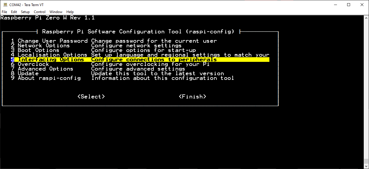
5 Interfacing Options. (Click to enlarge) Then, select P6 Serial.
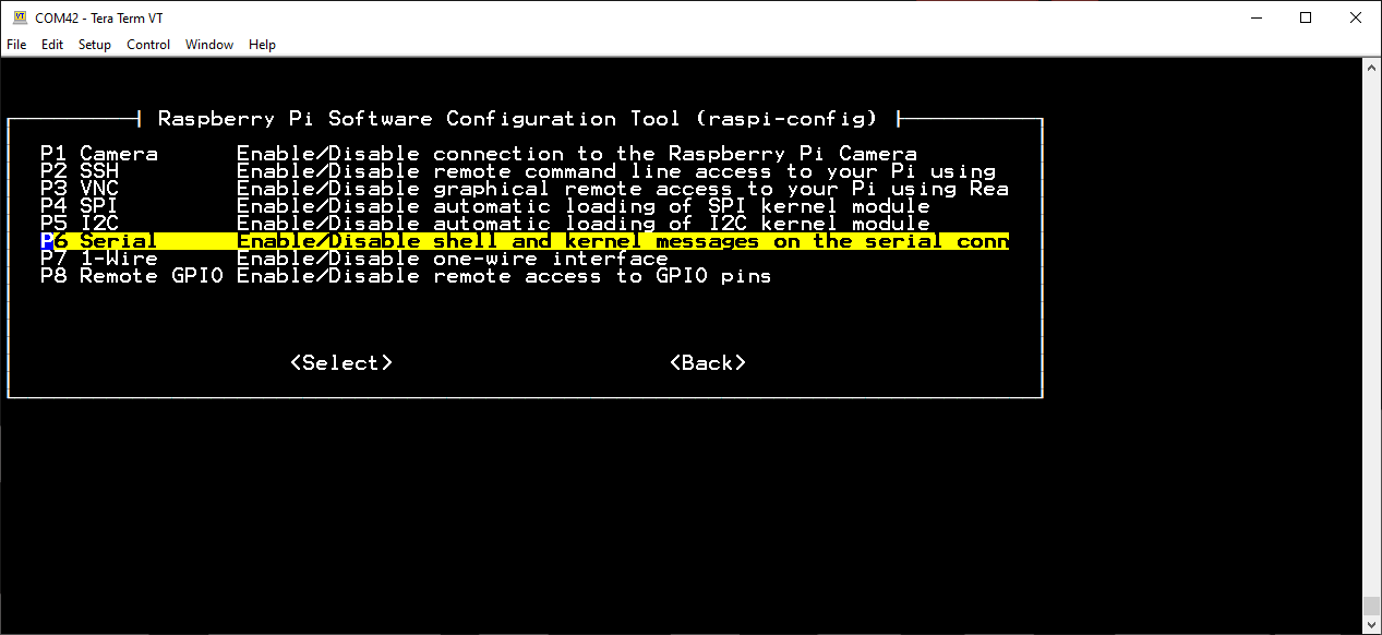
P6 Serial. (Click to enlarge) Once prompted:
Would you like a login shell to be accessible over serial?, select <NO>.
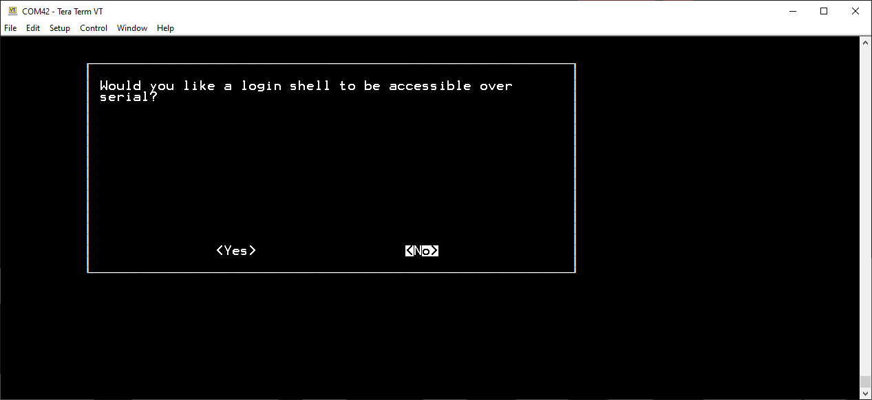
<NO> on login shell prompt. (Click to enlarge) Would you like the serial port hardware to be enabled?, select <YES>.
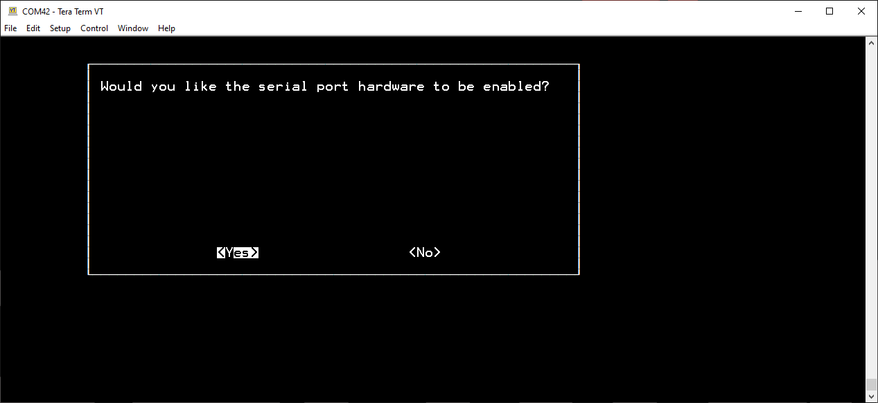
<YES> on serial port prompt. (Click to enlarge) Once configured, the configuration tool should display:
The serial login shell is disabled
The serial interface is enabled
Select <Ok> to proceed back to the main menu.
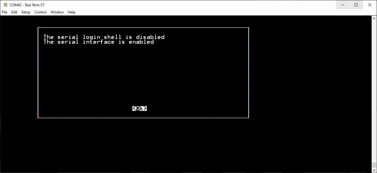
<Ok> to proceed back to the main menu. (Click to enlarge) With both the WiFi and serial port modifications made, use the Tab key to select <Finish>.
<Finish> on close the raspi-config tool. (Click to enlarge) When prompted Would you like to reboot now?, select <NO>.
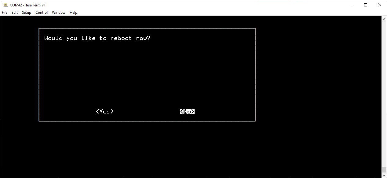
<NO> on reboot prompt. (Click to enlarge) (*More information on the raspi-config tool can be found on the Raspberry Pi Foundation's website.)
Selecting <NO> will allow users to check the IP address of the Raspberry Pi on the WiFi network before rebooting. Users should move on to the Retrieving the IP Address of the Raspberry Pi section below. (*On the next power up, the serial console will be disabled.)
Note: For users wanting to edit the configuration files directly, use the following commands:
sudo nano /etc/wpa_supplicant/wpa_supplicant.conf
sudo nano /boot/config.txt
Pixel Desktop
Disabling the Login Shell
To disable the login shell, click on the raspberry icon on the task bar. Scroll to Preferences > Raspberry Pi Configuration. In the configuration menu, select the Interfaces tab and then disable the Serial Console.
Raspberry Pi configuration settings.
(Click to enlarge)
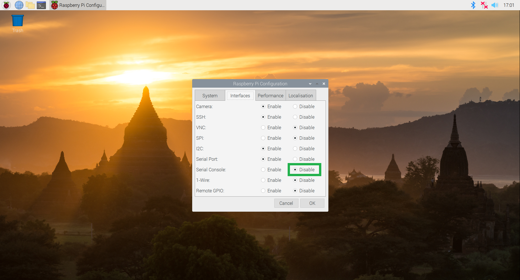
Interface configuration settings. (Click to enlarge)
Note: Again, users can use the Terminal application or the Linux console to modify the files directly or access the raspi-config tool.
Retrieving the IP Address of the Raspberry Pi
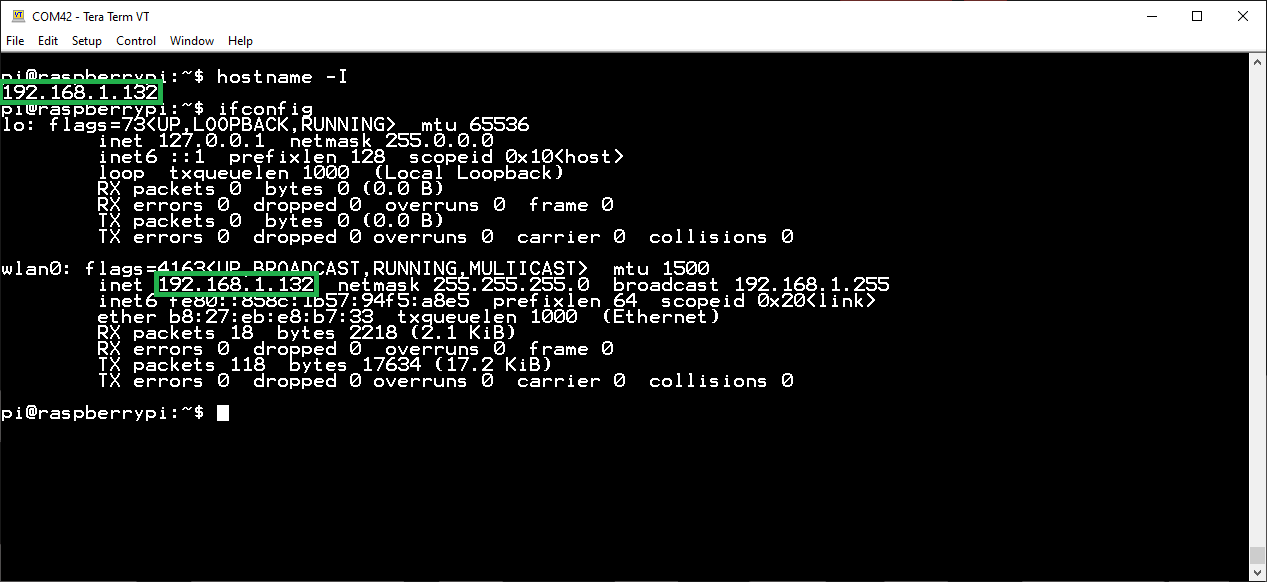
Once users are done with the WiFi and serial port configuration process, pull up the IP address for the Raspberry Pi using the Terminal or Linux console (if not already open). With either the hostname -I or ifconfig commands, users can retrieve the IP address. (*Users who followed the SD card method will not be able to access the Linux console in order to retrieve the IP address. Don't worry, there are special instructions for these users in the following sections.)
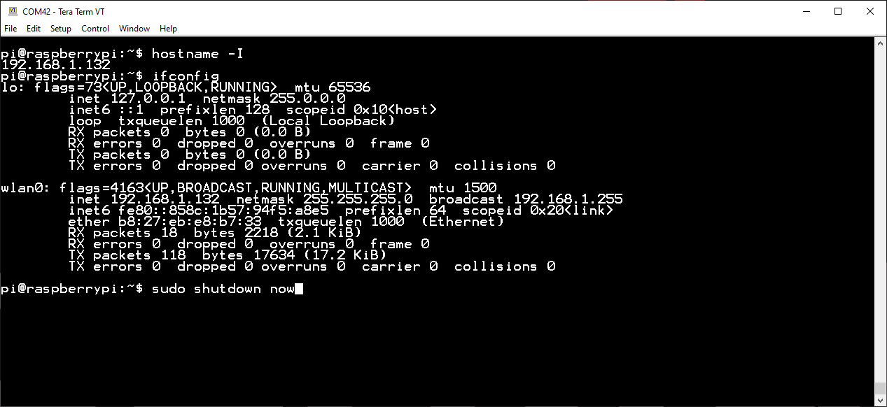
Once the IP address has been retrieved, users can shutdown the Raspberry Pi with the sudo shutdown now command.
Note: Don't forget to make sure that the Raspberry Pi is completely done shutting down before disconnecting the power. This is to avoid corrupting the SD card while the Raspberry Pi is in the middle of its power down cycle. Users should see the ACT LED blink 10 times steadily before a long "on" blink; about 5-10 seconds after, it should be safe to disconnect the power.
ACT LED indicating the end of the power down sequence, right before the power can be disconnected. The ACT LED will blink 10 times, followed by a long "on" blink. (Click to enlarge)