Digital Sandbox Arduino Companion
4. Dimming (the Easy Way)
Manual PWM is hard, and it doesn't leave room for anything else in the program. Why can't we offload that chore to the Digital Sandbox's microcontroller? It's smart enough for that...right?
Background Information
PWM is such a popular tool many microcontrollers implement special hardware so they can mindlessly toggle the pin while doing something else. We call this PWM-based output analog output.
Unlike digital outputs, which only have two possible values, analog outputs have a huge range of possible values. On the Sandbox we can analog-ly output 256 different values. If we set an analog output to zero, that's like setting a pin LOW, and 255 is like setting a pin HIGH, but all of the values in between produce an output that's neither HIGH or LOW -- it's somewhere in between.
Analog output seems great -- why wouldn't you use it all the time? Unfortunately, not all pins have special PWM powers. Only pins 3, 5, 6, 9, 10 and 11 are able to produce analog outputs.
Active Parts
Code Components
It's time to introduce digitalWrite()'s analog analogue: analogWrite().
Analog Output: analogWrite([pin], [0-255])
The analogWrite() function looks a lot like digitalWrite(). We still tell it which pin to control, but instead of a restrictive, digital output option, we get to choose any number between zero and 255 for the output.
There are two parameters to analogWrite(). The first is our pin, and the second is any value between 0 and 255. A 0 will output 0V, 255 will output 5V, 128 will do about 2.5V, and so on.
Unfortunately, not every pin is capable of analog output. You can only use analogWrite() on pins 3, 5, 6, 9, 10, and 11.
Sketch and Experiment
Here's our sketch, check out the code comments for help deciphering it. Open the Sandbox_04_Dimming_Easy.ino sketch or copy and paste from below. Upload away!
language:c
 // Sandbox 04: Dimming (the Easy Way)

/* Manual PWM is hard, and it doesn't leave room for anything else in the
   program. Why can't we offload that chore to the Digital Sandbox's
   microcontroller? It's smart enough for that...right?

   This experiment introduces the analogWrite([pin], [0-255]) function.
   analogWrite is used to output an analog voltage on a pin. So not only can we
   output 0V and 5V, but we can also do 254 voltages in between. Need 2.5V
   analogWrite to 128. Need 3.3V? Analog write 168.

   Unfortunately, not all pins can do analog output. Only pins 3, 5, 6, 9, 10,
   and 11 have the special ability.
*/

// As usual, in setup we need to set our LED pin as an OUTPUT.
void setup()
{
    pinMode(5, OUTPUT); // Set pin 5 to an output
}

// In loop we'll cycle the pin 5 LED through five different brightness levels
// from fully off, to dim, to half-on, to full-on. Then we go back to off and
// do it all over again.
void loop()
{
    analogWrite(5, 0);  // Sets voltage to 0V (0/255 * 5V). LED is off.
    delay(1000);        // Wait a second

    analogWrite(5, 64); // Sets voltage to ~1.25V (64/255 * 5V). Pretty dim.
    delay(1000);        // Wait a second

    analogWrite(5, 128);// Set voltage to ~2.5V. Half-bright.
    delay(1000);        // Wait a second

    analogWrite(5, 192);// Set voltage to ~3.75V. Getting brighter!
    delay(1000);        // Wait a second

    analogWrite(5, 255);// Set voltage to 5V. Fully on (turn down for what!?).
    delay(1000);        // Wait a second
}
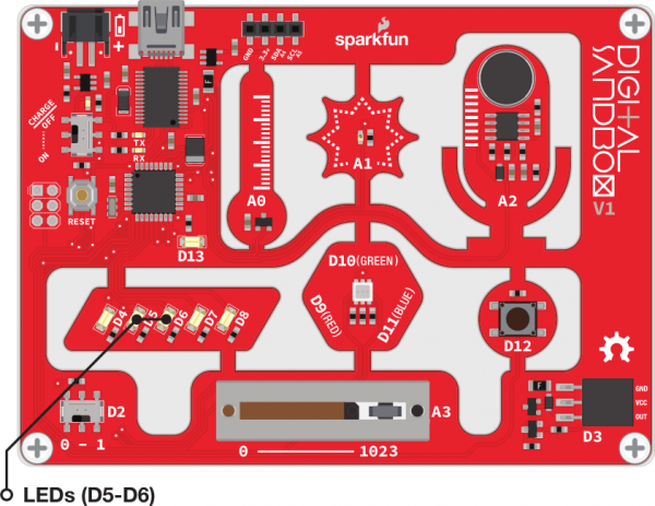
After uploading, keep an eye on the D5 LED. Can you identify 5 different levels of brightness (including off)? Don't stare at the LEDs for too long.
Your Turn!
- What's the dimmest value you can set the LED and still see it on?
- Can you add more brightness levels to the sketch to make it ramp up more smoothly? Get your copy/paste engines roaring!
- Why do you think there are 256 possible analog output values? That doesn't seem like a very round number (hint: 28).
