Digital Sandbox Arduino Companion
 jimblom
2. Multi-Blink
Background Information
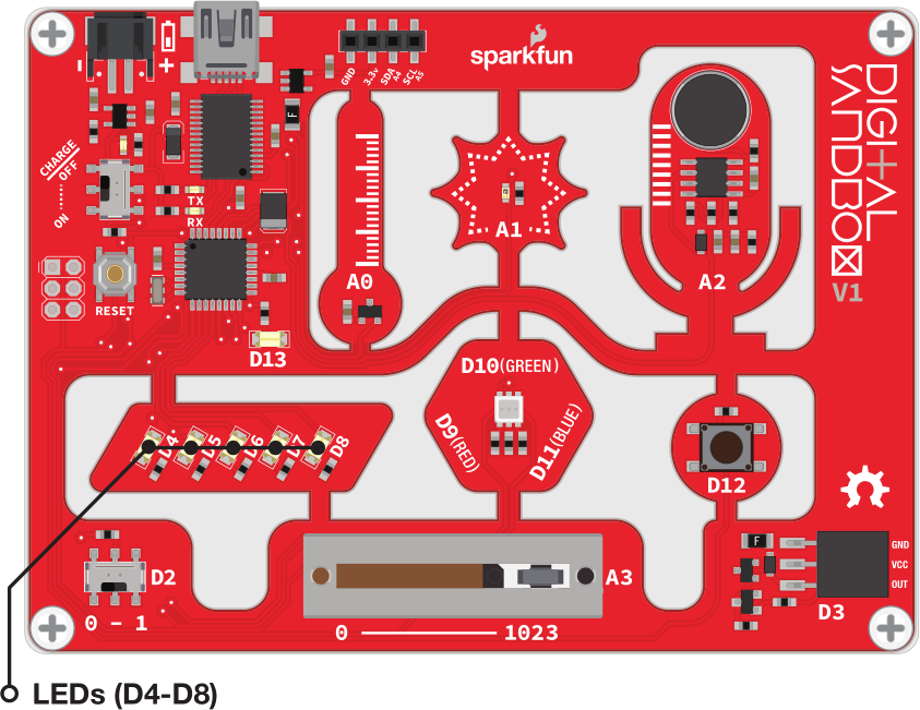
In this experiment we explore the subject of pins -- the manipulators of the Sandbox. Each LED (as well as the other inputs and outputs on the Digital Sandbox) is connected to a specific pin on the Sandbox's microcontroller.
Pins are all uniquely numbered, and each input or output component on the Sandbox is labeled with the pin number it's connected to -- that's the D2, D4, D11, A1, etc. lettering next to each LED, switch and sensor.
Every pin can be separately controlled; for instance pin 4 can be set HIGH at the same time pin 5 is set LOW. Some pins (as we'll later discover) have special powers, but every pin is at least able to accomplish digital input and output.
Active Parts
Code Components
Just one new function to introduce here. We kind of cheated last time by not using it, so we'll use it five times in this experiment.
Pin Mode: pinMode([pin], [INPUT/OUTPUT])
Every pin on an Arduino can be used as either an input or output, and one of your jobs is telling it which pin is which. To tell an Arduino what a pin's job is, you use the pinMode() function.
pinMode() takes two parameters inside its parenthesis. The first value is the pin that you want to set as an input or output. The second parameter is the mode, which can be either INPUT or OUTPUT. That's case-sensitive, those mode values need to be all caps!
Usually you'll stick your pinMode() declarations at the top of your sketch, in the setup() function. It only needs to run once, at the very start of your program, the pin will be set up that way for the rest of the sketch's run.
Sketch and Experiment
Here's our sketch, upload away! This is the Sandbox_02_MultiBlink.ino sketch.
language:c
// Sandbox 02: Multi-Blink

/* Large arrays of LEDs are often used to create massive outdoor signs and
   animations because they're both bright and efficient. While we don't have the
   millions of LED pixels that a display in Times Square might have, we can
   still create some fun patterns with the Digital Sandbox.

   This experiment introduces the pinMode([pin], [INPUT/OUTPUT]) function.

   It also explores the subject of PINs. Pins are all uniquely numbered, and
   each input or output component on the Sandbox is labeled with the pin number
   it's connected to -- that's the D2, D4, D11, A1, etc. lettering next to each
   LED, switch and sensor.

   When we call a pinMode or digitalWrite function, we always have to declare
   which pin we want to control. That's usually done with the literal value
   (e.g. 4, 13, 8, etc) of the pin
*/

// The setup function will allow us to set the mode of each pin to OUTPUT.
void setup()
{
    pinMode(4, OUTPUT); // Set pin D4 as an OUTPUT
    pinMode(5, OUTPUT); // Set pin D5 as an OUTPUT
    pinMode(6, OUTPUT); // Set pin D6 as an OUTPUT
    pinMode(7, OUTPUT); // Set pin D7 as an OUTPUT
    pinMode(8, OUTPUT); // Set pin D8 as an OUTPUT
}

// The loop function will be used to blink each of our LEDs in succession.
void loop()
{
    digitalWrite(4, HIGH);  // Turn the D4 LED on (HIGH)
    delay(500);             // Wait half a second (500 ms)
    digitalWrite(4, LOW);   // Turn the D4 LED off (LOW)

    digitalWrite(5, HIGH);  // Turn the D5 LED on (HIGH)
    delay(500);             // Wait half a second (500 ms)
    digitalWrite(5, LOW);   // Turn the D5 LED off (LOW)

    digitalWrite(6, HIGH);  // Turn the D6 LED on (HIGH)
    delay(500);             // Wait half a second (500 ms)
    digitalWrite(6, LOW);   // Turn the D6 LED off (LOW)

    digitalWrite(7, HIGH);  // Turn the D7 LED on (HIGH)
    delay(500);             // Wait half a second (500 ms)
    digitalWrite(7, LOW);   // Turn the D7 LED off (LOW)

    digitalWrite(8, HIGH);  // Turn the D8 LED on (HIGH)
    delay(500);             // Wait half a second (500 ms)
    digitalWrite(8, LOW);   // Turn the D8 LED off (LOW)
}
Notice how each of our pinMode() declarations occur in the setup() function. Then the loop() is used to write each of those LEDs either HIGH or LOW.
Your Turn!
- Try adding more blocks of code to create slicker patterns. Can you make a Larson scanner (ask an old person about Cylons or Knight Rider)? A chaser? Flip from odds to evens?
- Try turning on more than one LED at a time. Turn them all on (and shield your eyes)!